User Manual
Page 3
Contents 1 Introduction 5 1.1 Package Contents 5 1.2 Specifications 6 1.3 Motherboard Layout (G41C-GS / G41C-S 11 1.4 I/O Panel (G41C-GS 12 1.5 I/O Panel (G41C-S 13 2 Installation 14 2.1 Screw Holes 14 2.2 Pre-installation Precautions 14 2.3 CPU Installation 15 2.4 Installation of...SATA) / Serial ATAII (SATAII) Hard Disks Installation 26 2.11 Driver Installation Guide 26 2.12 Untied Overclocking Technology 26 3 BIOS SETUP UTILITY 27 3.1 Introduction 27 3.1.1 BIOS Menu Bar 27 3.1.2 Navigation Keys 28 3.2 Main Screen 28 3.3 OC Tweaker Screen 30 3.4 Advanced Screen 34 3.4.1 CPU ...
Contents 1 Introduction 5 1.1 Package Contents 5 1.2 Specifications 6 1.3 Motherboard Layout (G41C-GS / G41C-S 11 1.4 I/O Panel (G41C-GS 12 1.5 I/O Panel (G41C-S 13 2 Installation 14 2.1 Screw Holes 14 2.2 Pre-installation Precautions 14 2.3 CPU Installation 15 2.4 Installation of...SATA) / Serial ATAII (SATAII) Hard Disks Installation 26 2.11 Driver Installation Guide 26 2.12 Untied Overclocking Technology 26 3 BIOS SETUP UTILITY 27 3.1 Introduction 27 3.1.1 BIOS Menu Bar 27 3.1.2 Navigation Keys 28 3.2 Main Screen 28 3.3 OC Tweaker Screen 30 3.4 Advanced Screen 34 3.4.1 CPU ...
User Manual
Page 5
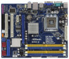
...ASRock G41C-GS / G41C-S Quick Installation Guide ASRock G41C-GS / G41C-S Support CD Two Serial ATA (SATA) Data Cables (Optional) One I/O Panel Shield 5 ASRock website http://www.asrock.com If you are using. In this manual, chapter 1 and 2 contain introduction of this manual will be subject to change without further notice. Because the motherboard specifications and the BIOS...to ASRock's commitment to BIOS setup and information of this motherboard, please visit our website for purchasing ASRock G41C-GS / G41C-S motherboard, a reliable motherboard produced under ASRock's consistently ...
...ASRock G41C-GS / G41C-S Quick Installation Guide ASRock G41C-GS / G41C-S Support CD Two Serial ATA (SATA) Data Cables (Optional) One I/O Panel Shield 5 ASRock website http://www.asrock.com If you are using. In this manual, chapter 1 and 2 contain introduction of this manual will be subject to change without further notice. Because the motherboard specifications and the BIOS...to ASRock's commitment to BIOS setup and information of this motherboard, please visit our website for purchasing ASRock G41C-GS / G41C-S motherboard, a reliable motherboard produced under ASRock's consistently ...

User Manual
Page 7
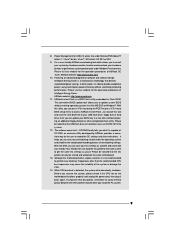
Front panel audio connector - 2 x USB 2.0 headers (support 4 USB 2.0 ports) (see CAUTION 9) - SMBIOS 2.3.1 Support - ASRock OC Tuner (see CAUTION 8) - 8Mb AMI BIOS - Intelligent Energy Saver (see CAUTION 7) - 1 x ATA100 IDE connector (supports 2 x IDE devices) - 1 x Floppy connector - 1 x Print port ...see CAUTION 10) - ACPI 1.1 Compliance Wake Up Events - Instant Boot - Hybrid Booster: - CPU/Chassis/Power Fan Tachometer - AMI Legal BIOS - ASRock OC DNA (see CAUTION 13) - Boot Failure Guard (B.F.G.) - VCCM, NB, VTT, GTLRef Voltage Multi-adjustment - CPU Temperature Sensing - ...
Front panel audio connector - 2 x USB 2.0 headers (support 4 USB 2.0 ports) (see CAUTION 9) - SMBIOS 2.3.1 Support - ASRock OC Tuner (see CAUTION 8) - 8Mb AMI BIOS - Intelligent Energy Saver (see CAUTION 7) - 1 x ATA100 IDE connector (supports 2 x IDE devices) - 1 x Floppy connector - 1 x Print port ...see CAUTION 10) - ACPI 1.1 Compliance Wake Up Events - Instant Boot - Hybrid Booster: - CPU/Chassis/Power Fan Tachometer - AMI Legal BIOS - ASRock OC DNA (see CAUTION 13) - Boot Failure Guard (B.F.G.) - VCCM, NB, VTT, GTLRef Voltage Multi-adjustment - CPU Temperature Sensing - ...

User Manual
Page 8
.... 4. We are not responsible for details. 3. About the setting of memory modules on this motherboard, it will operate in the BIOS, applying Untied Overclocking Technology, or using the thirdparty overclocking tools. Before you need to SATAII mode. CPU FSB Frequency Memory Support Frequency...EuP Ready (EuP ready power supply is required) (see CAUTION 15) * For detailed product information, please visit our website: http://www.asrock.com WARNING Please realize that there is no such limitation. 6. It should be less than 4GB for the reservation for proper jumper settings....
.... 4. We are not responsible for details. 3. About the setting of memory modules on this motherboard, it will operate in the BIOS, applying Untied Overclocking Technology, or using the thirdparty overclocking tools. Before you need to SATAII mode. CPU FSB Frequency Memory Support Frequency...EuP Ready (EuP ready power supply is required) (see CAUTION 15) * For detailed product information, please visit our website: http://www.asrock.com WARNING Please realize that there is no such limitation. 6. It should be less than 4GB for the reservation for proper jumper settings....
User Manual
Page 9
... To improve heat dissipation, remember to spray thermal grease between the CPU and the heatsink when you to your BIOS only in Flash ROM. ASRock website: http://www.asrock.com 10. ASRock website: http://www.asrock.com 11. It helps you install the PC system. 9 With this tool and save the new... BIOS file to save your hardware devices to update system BIOS without entering operating systems first like MS-DOS or ...
... To improve heat dissipation, remember to spray thermal grease between the CPU and the heatsink when you to your BIOS only in Flash ROM. ASRock website: http://www.asrock.com 10. ASRock website: http://www.asrock.com 11. It helps you install the PC system. 9 With this tool and save the new... BIOS file to save your hardware devices to update system BIOS without entering operating systems first like MS-DOS or ...
User Manual
Page 11
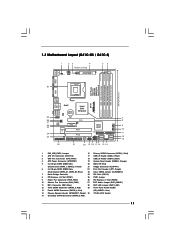
... Header (USB4_5, Blue) 4 ATX Power Connector (ATXPWR1) 19 System Panel Header (PANEL1, Orange) 5 2 x 240-pin DDR2 DIMM Slots 20 BIOS SPI Chip (Dual Channel: DDRII_1, DDRII_2; Red) (HD_AUDIO1, Lime) 14 Chassis Speaker Header (SPEAKER 1, Purple) 30 775-Pin CPU Socket 15 Secondary...Connector (FLOPPY1) 6 2 x 240-pin DDR3 DIMM Slots 22 Print Port Header (LPT1, Purple) (Dual Channel: DDR3_A1, DDR3_B1; 1.3 Motherboard Layout (G41C-GS / G41C-S) 1 23 4 19.8cm (7.8 in) 1 PS2_USB_PWR1 ATX12V2 CPU_FAN1 56 PS2 Mouse PS2 Keyboard COM1 24.4cm (9.6 in) DDR3_B1 (64 bit, 240-...
... Header (USB4_5, Blue) 4 ATX Power Connector (ATXPWR1) 19 System Panel Header (PANEL1, Orange) 5 2 x 240-pin DDR2 DIMM Slots 20 BIOS SPI Chip (Dual Channel: DDRII_1, DDRII_2; Red) (HD_AUDIO1, Lime) 14 Chassis Speaker Header (SPEAKER 1, Purple) 30 775-Pin CPU Socket 15 Secondary...Connector (FLOPPY1) 6 2 x 240-pin DDR3 DIMM Slots 22 Print Port Header (LPT1, Purple) (Dual Channel: DDR3_A1, DDR3_B1; 1.3 Motherboard Layout (G41C-GS / G41C-S) 1 23 4 19.8cm (7.8 in) 1 PS2_USB_PWR1 ATX12V2 CPU_FAN1 56 PS2 Mouse PS2 Keyboard COM1 24.4cm (9.6 in) DDR3_B1 (64 bit, 240-...

User Manual
Page 20
... of the expansion card and make sure that you install the add-on PCI Express VGA card to PCIE1 (PCIE x16 slot) and adjust the BIOS options "Primary Graphics Adapter" to [Onboard] and "Share Memory" to PCIE1 (PCIE x16 slot), the onboard VGA will be disabled. Fasten the card to install...
... of the expansion card and make sure that you install the add-on PCI Express VGA card to PCIE1 (PCIE x16 slot) and adjust the BIOS options "Primary Graphics Adapter" to [Onboard] and "Share Memory" to PCIE1 (PCIE x16 slot), the onboard VGA will be disabled. Fasten the card to install...

User Manual
Page 23
.... High Definition Audio supports Jack Sensing, but the panel wire on the motherboard. Connect Audio_R (RIN) to OUT2_R and Audio_L (LIN) to function correctly. D. Enter BIOS Setup Utility.
.... High Definition Audio supports Jack Sensing, but the panel wire on the motherboard. Connect Audio_R (RIN) to OUT2_R and Audio_L (LIN) to function correctly. D. Enter BIOS Setup Utility.
User Manual
Page 26
STEP 4: Connect the other end of BIOS setup to set the selection from up to bottom side to the warning on page 8 for internal storage devices. STEP 2: Connect the SATA power cable ...
STEP 4: Connect the other end of BIOS setup to set the selection from up to bottom side to the warning on page 8 for internal storage devices. STEP 2: Connect the SATA power cable ...

User Manual
Page 27
...back on the menu bar, and then press to get into the sub screen. 27 The SPI Memory on the system chassis. Because the BIOS software is constantly being updated, the following selections: Main To set up the system time/date information OC Tweaker To set up overclocking features ...Advanced To set up the advanced BIOS features H/W Monitor To display current hardware status Boot To set up the computer. You may also restart by pressing the reset button on the...
...back on the menu bar, and then press to get into the sub screen. 27 The SPI Memory on the system chassis. Because the BIOS software is constantly being updated, the following selections: Main To set up the system time/date information OC Tweaker To set up overclocking features ...Advanced To set up the advanced BIOS features H/W Monitor To display current hardware status Boot To set up the computer. You may also restart by pressing the reset button on the...
User Manual
Page 28
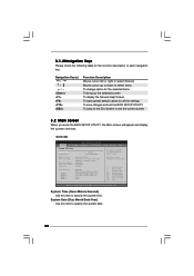
... Use this item to specify the system time. System Time [Hour:Minute:Second] Use this item to specify the system date. 28 G41C-GS BIOS SETUP UTILITY Main OC Tweaker Advanced H/W Monitor Boot Security Exit System Overview System Time System Date [14:00:09] [Tue 12/01/... ESC Select Screen Select Item Change Field Select Field General Help Load Defaults Save and Exit Exit v02.54 (C) Copyright 1985-2005, American Megatrends, Inc. BIOS Version : G41C-GS P1.00 Processor Type : Intel (R) Core (TM) 2 Duo CPU E8200 @ 2.66GHz (64bit) Processor Speed : 2666MHz Microcode Update : 10676/...
... Use this item to specify the system time. System Time [Hour:Minute:Second] Use this item to specify the system date. 28 G41C-GS BIOS SETUP UTILITY Main OC Tweaker Advanced H/W Monitor Boot Security Exit System Overview System Time System Date [14:00:09] [Tue 12/01/... ESC Select Screen Select Item Change Field Select Field General Help Load Defaults Save and Exit Exit v02.54 (C) Copyright 1985-2005, American Megatrends, Inc. BIOS Version : G41C-GS P1.00 Processor Type : Intel (R) Core (TM) 2 Duo CPU E8200 @ 2.66GHz (64bit) Processor Speed : 2666MHz Microcode Update : 10676/...
User Manual
Page 29
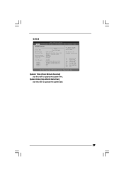
...] Use this item to specify the system date. 29 System Time [Hour:Minute:Second] Use this item to specify the system time. G41C-S BIOS SETUP UTILITY Main OC Tweaker Advanced H/W Monitor Boot Security Exit System Overview System Time System Date [14:00:09] [Tue 12/01/...ESC Select Screen Select Item Change Field Select Field General Help Load Defaults Save and Exit Exit v02.54 (C) Copyright 1985-2005, American Megatrends, Inc. BIOS Version : G41C-S P1.00 Processor Type : Intel (R) Core (TM) 2 Duo CPU E8200 @ 2.66GHz (64bit) Processor Speed : 2666MHz Microcode Update : 10676/60C...
...] Use this item to specify the system date. 29 System Time [Hour:Minute:Second] Use this item to specify the system time. G41C-S BIOS SETUP UTILITY Main OC Tweaker Advanced H/W Monitor Boot Security Exit System Overview System Time System Date [14:00:09] [Tue 12/01/...ESC Select Screen Select Item Change Field Select Field General Help Load Defaults Save and Exit Exit v02.54 (C) Copyright 1985-2005, American Megatrends, Inc. BIOS Version : G41C-S P1.00 Processor Type : Intel (R) Core (TM) 2 Duo CPU E8200 @ 2.66GHz (64bit) Processor Speed : 2666MHz Microcode Update : 10676/60C...
User Manual
Page 30
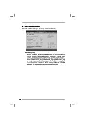
...] [8] [Auto] [Auto] [333] [100] If you adopt on this motherboard. The configuration options depend on the CPU and memory module you adopt DDR3 1333 pls. BIOS SETUP UTILITY Main OC Tweaker Advanced H/W Monitor Boot Security Exit OC Tweaker Settings DRAM Frequency DRAM Timing Configuration Ratio CMOS Setting 8 Intel (R) SpeedStep (tm) tech...
...] [8] [Auto] [Auto] [333] [100] If you adopt on this motherboard. The configuration options depend on the CPU and memory module you adopt DDR3 1333 pls. BIOS SETUP UTILITY Main OC Tweaker Advanced H/W Monitor Boot Security Exit OC Tweaker Settings DRAM Frequency DRAM Timing Configuration Ratio CMOS Setting 8 Intel (R) SpeedStep (tm) tech...

User Manual
Page 31
... for TRTP. Max: 24. The default value is [Auto]. Min: 3. DRAM tRTP This controls the number of DRAM clocks for TWR. Min: 2. DRAM Timing Configuration BIOS SETUP UTILITY OC Tweaker DRAM Timing Control DRAM tCL 6 DRAM tRCD 6 DRAM tRP 6 DRAM tRAS 15 DRAM tRFC 44 DRAM tWR 6 DRAM tWTR 4 DRAM tRRD...
... for TRTP. Max: 24. The default value is [Auto]. Min: 3. DRAM tRTP This controls the number of DRAM clocks for TWR. Min: 2. DRAM Timing Configuration BIOS SETUP UTILITY OC Tweaker DRAM Timing Control DRAM tCL 6 DRAM tRCD 6 DRAM tRP 6 DRAM tRAS 15 DRAM tRFC 44 DRAM tWR 6 DRAM tWTR 4 DRAM tRRD...

User Manual
Page 34
CPU Configuration Chipset Configuration ACPI Configuration Storage Configuration PCIPnP Configuration Floppy Configuration SuperIO Configuration USB Configuration BIOS Update Utility ASRock Instant Flash Select Screen Select Item Enter Go to malfunction. BIOS SETUP UTILITY Main OC Tweaker Advanced H/W Monitor Boot Security Exit Advanced Settings Options for the following items: CPU Configuration, Chipset Configuration, ACPI Configuration...
CPU Configuration Chipset Configuration ACPI Configuration Storage Configuration PCIPnP Configuration Floppy Configuration SuperIO Configuration USB Configuration BIOS Update Utility ASRock Instant Flash Select Screen Select Item Enter Go to malfunction. BIOS SETUP UTILITY Main OC Tweaker Advanced H/W Monitor Boot Security Exit Advanced Settings Options for the following items: CPU Configuration, Chipset Configuration, ACPI Configuration...

User Manual
Page 35
... EIST (Intel (R) SpeedStep(tm) tech.), and you changing the ratio value of this item appear to allow you plan to adjust CPU frequency. 3.4.1 CPU Configuration BIOS SETUP UTILITY Advanced CPU Configuration Overclock Mode CPU Frequency (MHz) PCIE Frequency (MHz) Boot Failure Guard Spread Spectrum Ratio CMOS Setting 8 Enhanced Halt State Intel...
... EIST (Intel (R) SpeedStep(tm) tech.), and you changing the ratio value of this item appear to allow you plan to adjust CPU frequency. 3.4.1 CPU Configuration BIOS SETUP UTILITY Advanced CPU Configuration Overclock Mode CPU Frequency (MHz) PCIE Frequency (MHz) Boot Failure Guard Spread Spectrum Ratio CMOS Setting 8 Enhanced Halt State Intel...

User Manual
Page 37
...DRAM CH0 G1 (Command). DRAM CH0 G2 (Control1) This controls the number of DRAM CH0 G0 (Data). DRAM RCOMP and tRD Configuration BIOS SETUP UTILITY Advanced DRAM RCOMP STRENGTH Settings DRAM CH0 RCOMP Settings : 54-0-11-6-6-6-6 DRAM CH0 RCOMP ODT [Auto] DRAM CH0 G0 (Data... Save and Exit Exit v02.54 (C) Copyright 1985-2005, American Megatrends, Inc. The default value is [Auto]. 3.4.2 Chipset Configuration BIOS SETUP UTILITY Advanced Chipset Settings DRAM RCOMP and tRD Configuration DRAM DLL SKEW Configuration Fixed Mode Operation [Enabled] Intelligent Energy Saver Primary Graphics...
...DRAM CH0 G1 (Command). DRAM CH0 G2 (Control1) This controls the number of DRAM CH0 G0 (Data). DRAM RCOMP and tRD Configuration BIOS SETUP UTILITY Advanced DRAM RCOMP STRENGTH Settings DRAM CH0 RCOMP Settings : 54-0-11-6-6-6-6 DRAM CH0 RCOMP ODT [Auto] DRAM CH0 G0 (Data... Save and Exit Exit v02.54 (C) Copyright 1985-2005, American Megatrends, Inc. The default value is [Auto]. 3.4.2 Chipset Configuration BIOS SETUP UTILITY Advanced Chipset Settings DRAM RCOMP and tRD Configuration DRAM DLL SKEW Configuration Fixed Mode Operation [Enabled] Intelligent Energy Saver Primary Graphics...

User Manual
Page 39
... CLKSET0 SKEW. DRAM CH0 CTRL0 SKEW This controls the number of DRAM CH0 CTRL0 SKEW. The default value is [Auto]. 39 DRAM DLL SKEW Configuration BIOS SETUP UTILITY Advanced DRAM DLL SKEW Settings DRAM CH0 CLKSET0 SKEW Info:0-0-0-0-0-0 DRAM CH0 CLKSET0 SKEW [Auto] DRAM CH0 CLKSET1 SKEW Info:0-0-0-0-0-0 DRAM CH0 CLKSET1...
... CLKSET0 SKEW. DRAM CH0 CTRL0 SKEW This controls the number of DRAM CH0 CTRL0 SKEW. The default value is [Auto]. 39 DRAM DLL SKEW Configuration BIOS SETUP UTILITY Advanced DRAM DLL SKEW Settings DRAM CH0 CLKSET0 SKEW Info:0-0-0-0-0-0 DRAM CH0 CLKSET0 SKEW [Auto] DRAM CH0 CLKSET1 SKEW Info:0-0-0-0-0-0 DRAM CH0 CLKSET1...

User Manual
Page 41
Flex Mode Operation This allows you to enable this function. The default value is [PCI]. Besides the BIOS option, you can also choose our Intelligent Energy Saver utility to enable or disable flex mode operation feature. The default value is [Disabled]. DVMT (Dynamic ...
Flex Mode Operation This allows you to enable this function. The default value is [PCI]. Besides the BIOS option, you can also choose our Intelligent Energy Saver utility to enable or disable flex mode operation feature. The default value is [Disabled]. DVMT (Dynamic ...

User Manual
Page 42
... Power On Use this item to set this item to enable or disable PCI devices to enable or disable the "OnBoard Lan" feature. 3.4.3 ACPI Configuration BIOS SETUP UTILITY Advanced ACPI Configuration Suspend To RAM Restore on AC/Power Loss Ring-In Power On PCI Devices Power On PS / 2 Keyboard Power On...
... Power On Use this item to set this item to enable or disable PCI devices to enable or disable the "OnBoard Lan" feature. 3.4.3 ACPI Configuration BIOS SETUP UTILITY Advanced ACPI Configuration Suspend To RAM Restore on AC/Power Loss Ring-In Power On PCI Devices Power On PS / 2 Keyboard Power On...


