User Manual
Page 3
Contents 1 Introduction 5 1.1 Package Contents 5 1.2 Specifications 6 1.3 Motherboard Layout (G41C-GS / G41C-S 11 1.4 I/O Panel (G41C-GS 12 1.5 I/O Panel (G41C-S 13 2 Installation 14 2.1 Screw Holes 14 2.2 Pre-installation Precautions 14 2.3 CPU Installation 15 2.4 Installation of...SATA) / Serial ATAII (SATAII) Hard Disks Installation 26 2.11 Driver Installation Guide 26 2.12 Untied Overclocking Technology 26 3 BIOS SETUP UTILITY 27 3.1 Introduction 27 3.1.1 BIOS Menu Bar 27 3.1.2 Navigation Keys 28 3.2 Main Screen 28 3.3 OC Tweaker Screen 30 3.4 Advanced Screen 34 3.4.1 CPU ...
Contents 1 Introduction 5 1.1 Package Contents 5 1.2 Specifications 6 1.3 Motherboard Layout (G41C-GS / G41C-S 11 1.4 I/O Panel (G41C-GS 12 1.5 I/O Panel (G41C-S 13 2 Installation 14 2.1 Screw Holes 14 2.2 Pre-installation Precautions 14 2.3 CPU Installation 15 2.4 Installation of...SATA) / Serial ATAII (SATAII) Hard Disks Installation 26 2.11 Driver Installation Guide 26 2.12 Untied Overclocking Technology 26 3 BIOS SETUP UTILITY 27 3.1 Introduction 27 3.1.1 BIOS Menu Bar 27 3.1.2 Navigation Keys 28 3.2 Main Screen 28 3.3 OC Tweaker Screen 30 3.4 Advanced Screen 34 3.4.1 CPU ...
User Manual
Page 5
... without notice. Because the motherboard specifications and the BIOS software might be updated, the content of this motherboard, please visit our website for specific information about the model you for purchasing ASRock G41C-GS / G41C-S motherboard, a reliable motherboard produced under ASRock's consistently stringent quality control. ASRock website http://www.asrock.com If you require technical support related to...
... without notice. Because the motherboard specifications and the BIOS software might be updated, the content of this motherboard, please visit our website for specific information about the model you for purchasing ASRock G41C-GS / G41C-S motherboard, a reliable motherboard produced under ASRock's consistently stringent quality control. ASRock website http://www.asrock.com If you require technical support related to...
User Manual
Page 7
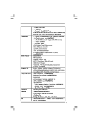
... Control (see CAUTION 14) - AMI Legal BIOS - ASRock U-COP (see CAUTION 13) - Chassis Temperature Sensing - ASRock OC DNA (see CAUTION 11) - Boot Failure Guard (B.F.G.) - Drivers, Utilities, AntiVirus Software (Trial Version), ASRock Software Suite (CyberLink DVD Suite and Creative Sound...- 4 x SATAII 3.0 Gb/s connectors (No Support for RAID and "Hot Plug" functions) (see CAUTION 9) - Supports "Plug and Play" - ASRock OC Tuner (see CAUTION 7) - 1 x ATA100 IDE connector (supports 2 x IDE devices) - 1 x Floppy connector - 1 x Print port header - Intelligent Energy Saver...
... Control (see CAUTION 14) - AMI Legal BIOS - ASRock U-COP (see CAUTION 13) - Chassis Temperature Sensing - ASRock OC DNA (see CAUTION 11) - Boot Failure Guard (B.F.G.) - Drivers, Utilities, AntiVirus Software (Trial Version), ASRock Software Suite (CyberLink DVD Suite and Creative Sound...- 4 x SATAII 3.0 Gb/s connectors (No Support for RAID and "Hot Plug" functions) (see CAUTION 9) - Supports "Plug and Play" - ASRock OC Tuner (see CAUTION 7) - 1 x ATA100 IDE connector (supports 2 x IDE devices) - 1 x Floppy connector - 1 x Print port header - Intelligent Energy Saver...

User Manual
Page 8
...667, DDR2 800 800 DDR3 800 DDR2 667, DDR2 800 533 DDR3 800 DDR2 533 * DDR3 1333 memory modules will operate in the BIOS, applying Untied Overclocking Technology, or using the thirdparty overclocking tools. Overclocking may be done at DDR3 533 if you adopt a DDR3 800 ...EuP Ready (EuP ready power supply is required) (see CAUTION 15) * For detailed product information, please visit our website: http://www.asrock.com WARNING Please realize that there is subject to change. This motherboard supports Untied Overclocking Technology. The maximum shared memory size is defined by...
...667, DDR2 800 800 DDR3 800 DDR2 667, DDR2 800 533 DDR3 800 DDR2 533 * DDR3 1333 memory modules will operate in the BIOS, applying Untied Overclocking Technology, or using the thirdparty overclocking tools. Overclocking may be done at DDR3 533 if you adopt a DDR3 800 ...EuP Ready (EuP ready power supply is required) (see CAUTION 15) * For detailed product information, please visit our website: http://www.asrock.com WARNING Please realize that there is subject to change. This motherboard supports Untied Overclocking Technology. The maximum shared memory size is defined by...
User Manual
Page 9
Please visit our website for the user to update system BIOS without sacrificing computing performance. ASRock Instant Flash is a BIOS flash utility embedded in a few clicks without preparing an additional floppy diskette or other words, it is detected, the system will ... Microsoft® Windows® 7 64-bit / 7 / VistaTM 64-bit / VistaTM / XP 64-bit / XP SP1 or SP2. 9. ASRock website: http://www.asrock.com 10. This convenient BIOS update tool allows you install the PC system. 9 OC DNA, an exclusive utility developed by hardware monitor function and overclock your system...
Please visit our website for the user to update system BIOS without sacrificing computing performance. ASRock Instant Flash is a BIOS flash utility embedded in a few clicks without preparing an additional floppy diskette or other words, it is detected, the system will ... Microsoft® Windows® 7 64-bit / 7 / VistaTM 64-bit / VistaTM / XP 64-bit / XP SP1 or SP2. 9. ASRock website: http://www.asrock.com 10. This convenient BIOS update tool allows you install the PC system. 9 OC DNA, an exclusive utility developed by hardware monitor function and overclock your system...
User Manual
Page 11
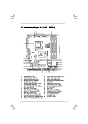
... EUP Audio Jumper (EUP_AUDIO1) 11 IDE1 Connector (IDE1, Blue) 28 EUP LAN Jumper (EUP_LAN1) 12 Third SATAII Connector (SATAII_3; 1.3 Motherboard Layout (G41C-GS / G41C-S) 1 23 4 19.8cm (7.8 in) 1 PS2_USB_PWR1 ATX12V2 CPU_FAN1 56 PS2 Mouse PS2 Keyboard COM1 24.4cm (9.6 in) DDR3_B1 (64 bit, 240... AUDIO CODEC CMOS Battery PCIE2 Super IO LPT1 1 CLRCMOS1 FLOPPY1 Intel G41 Chipset PCIE1 FSB1 1 PCI1 Intel ICH7 IDE1 PWR_FAN1 CHA_FAN1 PCI2 8Mb BIOS PANEL 1 PLED PWRBTN 1 HDLED RESET USB4_5 1 1 USB6_7 SATAII_1 SATAII_3 SATAII_2 SPEAKER1 1 SATAII_4 22 21 20 19 18 17 16 15 ...
... EUP Audio Jumper (EUP_AUDIO1) 11 IDE1 Connector (IDE1, Blue) 28 EUP LAN Jumper (EUP_LAN1) 12 Third SATAII Connector (SATAII_3; 1.3 Motherboard Layout (G41C-GS / G41C-S) 1 23 4 19.8cm (7.8 in) 1 PS2_USB_PWR1 ATX12V2 CPU_FAN1 56 PS2 Mouse PS2 Keyboard COM1 24.4cm (9.6 in) DDR3_B1 (64 bit, 240... AUDIO CODEC CMOS Battery PCIE2 Super IO LPT1 1 CLRCMOS1 FLOPPY1 Intel G41 Chipset PCIE1 FSB1 1 PCI1 Intel ICH7 IDE1 PWR_FAN1 CHA_FAN1 PCI2 8Mb BIOS PANEL 1 PLED PWRBTN 1 HDLED RESET USB4_5 1 1 USB6_7 SATAII_1 SATAII_3 SATAII_2 SPEAKER1 1 SATAII_4 22 21 20 19 18 17 16 15 ...
User Manual
Page 20
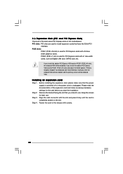
... the add-on the slot. PCIE2 (PCIE x1 slot) is completely seated on PCI Express VGA card to PCIE1 (PCIE x16 slot) and adjust the BIOS options "Primary Graphics Adapter" to [Onboard] and "Share Memory" to use . If you start the installation. PCIE slots: PCIE1 (PCIE x16 slot) is unplugged...
... the add-on the slot. PCIE2 (PCIE x1 slot) is completely seated on PCI Express VGA card to PCIE1 (PCIE x16 slot) and adjust the BIOS options "Primary Graphics Adapter" to [Onboard] and "Share Memory" to use . If you start the installation. PCIE slots: PCIE1 (PCIE x16 slot) is unplugged...
User Manual
Page 23
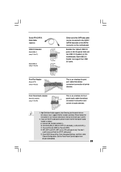
... end of the SATA data cable can support two USB 2.0 ports. Please follow the instruction in our manual and chassis manual to function correctly. C. Enter BIOS Setup Utility. High Definition Audio supports Jack Sensing, but the panel wire on the chassis must support HDA to install your system. 2. If you use...
... end of the SATA data cable can support two USB 2.0 ports. Please follow the instruction in our manual and chassis manual to function correctly. C. Enter BIOS Setup Utility. High Definition Audio supports Jack Sensing, but the panel wire on the chassis must support HDA to install your system. 2. If you use...
User Manual
Page 26
... chassis. STEP 4: Connect the other end of the SATA data cable to [Manual]. STEP 1: Install the SATA / SATAII hard disks into the drive bays of BIOS setup to set the selection from up to bottom side to fixed PCI / PCIE buses. Please refer to the SATA / SATAII hard disk. Before you...
... chassis. STEP 4: Connect the other end of the SATA data cable to [Manual]. STEP 1: Install the SATA / SATAII hard disks into the drive bays of BIOS setup to set the selection from up to bottom side to fixed PCI / PCIE buses. Please refer to the SATA / SATAII hard disk. Before you...
User Manual
Page 27
...date information OC Tweaker To set up overclocking features Advanced To set up the advanced BIOS features H/W Monitor To display current hardware status Boot To set up the security features Exit To exit... the current screen or the BIOS SETUP UTILITY Use < > key or < > key to choose among the selections on the menu ... screen. 27 You may also restart by pressing the reset button on . If you wish to enter the BIOS SETUP UTILITY after POST, restart the system by pressing + + , or by turning the system off and ...
...date information OC Tweaker To set up overclocking features Advanced To set up the advanced BIOS features H/W Monitor To display current hardware status Boot To set up the security features Exit To exit... the current screen or the BIOS SETUP UTILITY Use < > key or < > key to choose among the selections on the menu ... screen. 27 You may also restart by pressing the reset button on . If you wish to enter the BIOS SETUP UTILITY after POST, restart the system by pressing + + , or by turning the system off and ...
User Manual
Page 28
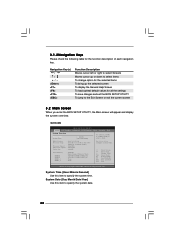
... UTILITY To jump to specify the system date. 28 System Date [Day Month/Date/Year] Use this item to specify the system time. BIOS Version : G41C-GS P1.00 Processor Type : Intel (R) Core (TM) 2 Duo CPU E8200 @ 2.66GHz (64bit) Processor Speed : 2666MHz Microcode Update : 10676/60C Cache ...this item to the Exit Screen or exit the current screen 3.2 Main Screen When you enter the BIOS SETUP UTILITY, the Main screen will appear and display the system overview. G41C-GS BIOS SETUP UTILITY Main OC Tweaker Advanced H/W Monitor Boot Security Exit System Overview System Time System Date ...
... UTILITY To jump to specify the system date. 28 System Date [Day Month/Date/Year] Use this item to specify the system time. BIOS Version : G41C-GS P1.00 Processor Type : Intel (R) Core (TM) 2 Duo CPU E8200 @ 2.66GHz (64bit) Processor Speed : 2666MHz Microcode Update : 10676/60C Cache ...this item to the Exit Screen or exit the current screen 3.2 Main Screen When you enter the BIOS SETUP UTILITY, the Main screen will appear and display the system overview. G41C-GS BIOS SETUP UTILITY Main OC Tweaker Advanced H/W Monitor Boot Security Exit System Overview System Time System Date ...
User Manual
Page 29
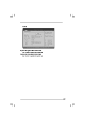
.../Date/Year] Use this item to specify the system date. 29 System Time [Hour:Minute:Second] Use this item to specify the system time. BIOS Version : G41C-S P1.00 Processor Type : Intel (R) Core (TM) 2 Duo CPU E8200 @ 2.66GHz (64bit) Processor Speed : 2666MHz Microcode Update : 10676... DDR3_2 : 2048MB Dual-Channel Memory Mode : 1024MB/333MHz DDR2_667 : 1024MB/333MHz DDR2_667 : None : None Use [+] or [-] to select a field. G41C-S BIOS SETUP UTILITY Main OC Tweaker Advanced H/W Monitor Boot Security Exit System Overview System Time System Date [14:00:09] [Tue 12/01/2009] Use ...
.../Date/Year] Use this item to specify the system date. 29 System Time [Hour:Minute:Second] Use this item to specify the system time. BIOS Version : G41C-S P1.00 Processor Type : Intel (R) Core (TM) 2 Duo CPU E8200 @ 2.66GHz (64bit) Processor Speed : 2666MHz Microcode Update : 10676... DDR3_2 : 2048MB Dual-Channel Memory Mode : 1024MB/333MHz DDR2_667 : 1024MB/333MHz DDR2_667 : None : None Use [+] or [-] to select a field. G41C-S BIOS SETUP UTILITY Main OC Tweaker Advanced H/W Monitor Boot Security Exit System Overview System Time System Date [14:00:09] [Tue 12/01/2009] Use ...
User Manual
Page 30
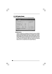
BIOS SETUP UTILITY Main OC Tweaker Advanced H/W Monitor Boot Security Exit OC Tweaker Settings DRAM Frequency DRAM Timing Configuration Ratio CMOS Setting 8 Intel (R) SpeedStep (tm) tech. ...
BIOS SETUP UTILITY Main OC Tweaker Advanced H/W Monitor Boot Security Exit OC Tweaker Settings DRAM Frequency DRAM Timing Configuration Ratio CMOS Setting 8 Intel (R) SpeedStep (tm) tech. ...
User Manual
Page 31
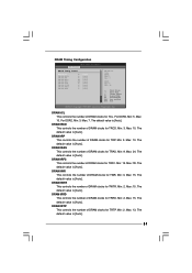
... This controls the number of DRAM clocks for TRFC. The default value is [Auto]. For DDR2, Min: 3. The default value is [Auto]. DRAM Timing Configuration BIOS SETUP UTILITY OC Tweaker DRAM Timing Control DRAM tCL 6 DRAM tRCD 6 DRAM tRP 6 DRAM tRAS 15 DRAM tRFC 44 DRAM tWR 6 DRAM tWTR 4 DRAM tRRD...
... This controls the number of DRAM clocks for TRFC. The default value is [Auto]. For DDR2, Min: 3. The default value is [Auto]. DRAM Timing Configuration BIOS SETUP UTILITY OC Tweaker DRAM Timing Control DRAM tCL 6 DRAM tRCD 6 DRAM tRP 6 DRAM tRAS 15 DRAM tRFC 44 DRAM tWR 6 DRAM tWTR 4 DRAM tRRD...
User Manual
Page 34
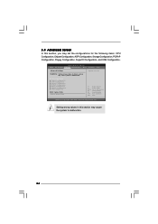
... in this section may cause system to malfunction. CPU Configuration Chipset Configuration ACPI Configuration Storage Configuration PCIPnP Configuration Floppy Configuration SuperIO Configuration USB Configuration BIOS Update Utility ASRock Instant Flash Select Screen Select Item Enter Go to malfunction. 34 Setting wrong values in below sections may cause the system to Sub Screen...
... in this section may cause system to malfunction. CPU Configuration Chipset Configuration ACPI Configuration Storage Configuration PCIPnP Configuration Floppy Configuration SuperIO Configuration USB Configuration BIOS Update Utility ASRock Instant Flash Select Screen Select Item Enter Go to malfunction. 34 Setting wrong values in below sections may cause the system to Sub Screen...
User Manual
Page 35
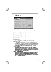
... EIST (Intel (R) SpeedStep(tm) tech.), and you changing the ratio value of this item appear to allow you plan to adjust PCIE frequency. 3.4.1 CPU Configuration BIOS SETUP UTILITY Advanced CPU Configuration Overclock Mode CPU Frequency (MHz) PCIE Frequency (MHz) Boot Failure Guard Spread Spectrum Ratio CMOS Setting 8 Enhanced Halt State Intel...
... EIST (Intel (R) SpeedStep(tm) tech.), and you changing the ratio value of this item appear to allow you plan to adjust PCIE frequency. 3.4.1 CPU Configuration BIOS SETUP UTILITY Advanced CPU Configuration Overclock Mode CPU Frequency (MHz) PCIE Frequency (MHz) Boot Failure Guard Spread Spectrum Ratio CMOS Setting 8 Enhanced Halt State Intel...
User Manual
Page 37
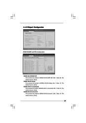
Min: 1. DRAM CH0 G0 (Data) This controls the number of DRAM CH0 RCOMP ODT. Min: 1. 3.4.2 Chipset Configuration BIOS SETUP UTILITY Advanced Chipset Settings DRAM RCOMP and tRD Configuration DRAM DLL SKEW Configuration Fixed Mode Operation [Enabled] Intelligent Energy Saver Primary ...default value is [Auto]. Max: 15. DRAM CH0 G2 (Control1) This controls the number of DRAM CH0 G1 (Command). DRAM RCOMP and tRD Configuration BIOS SETUP UTILITY Advanced DRAM RCOMP STRENGTH Settings DRAM CH0 RCOMP Settings : 54-0-11-6-6-6-6 DRAM CH0 RCOMP ODT [Auto] DRAM CH0 G0 (Data) [Auto] DRAM...
Min: 1. DRAM CH0 G0 (Data) This controls the number of DRAM CH0 RCOMP ODT. Min: 1. 3.4.2 Chipset Configuration BIOS SETUP UTILITY Advanced Chipset Settings DRAM RCOMP and tRD Configuration DRAM DLL SKEW Configuration Fixed Mode Operation [Enabled] Intelligent Energy Saver Primary ...default value is [Auto]. Max: 15. DRAM CH0 G2 (Control1) This controls the number of DRAM CH0 G1 (Command). DRAM RCOMP and tRD Configuration BIOS SETUP UTILITY Advanced DRAM RCOMP STRENGTH Settings DRAM CH0 RCOMP Settings : 54-0-11-6-6-6-6 DRAM CH0 RCOMP ODT [Auto] DRAM CH0 G0 (Data) [Auto] DRAM...
User Manual
Page 39
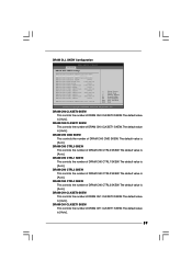
DRAM DLL SKEW Configuration BIOS SETUP UTILITY Advanced DRAM DLL SKEW Settings DRAM CH0 CLKSET0 SKEW Info:0-0-0-0-0-0 DRAM CH0 CLKSET0 SKEW [Auto] DRAM CH0 CLKSET1 SKEW Info:0-0-0-0-0-0 DRAM CH0 CLKSET1 ...
DRAM DLL SKEW Configuration BIOS SETUP UTILITY Advanced DRAM DLL SKEW Settings DRAM CH0 CLKSET0 SKEW Info:0-0-0-0-0-0 DRAM CH0 CLKSET0 SKEW [Auto] DRAM CH0 CLKSET1 SKEW Info:0-0-0-0-0-0 DRAM CH0 CLKSET1 ...
User Manual
Page 41
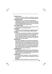
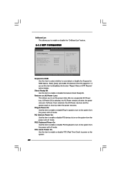
... applications and is an architecture that delivers unparalleled power savings. If you want to enable this function, please set this option to [Enabled]. Besides the BIOS option, you can also choose our Intelligent Energy Saver utility to set DVMT Mode Select as the boot graphic adapter priority. The default value is...
... applications and is an architecture that delivers unparalleled power savings. If you want to enable this function, please set this option to [Enabled]. Besides the BIOS option, you can also choose our Intelligent Energy Saver utility to set DVMT Mode Select as the boot graphic adapter priority. The default value is...
User Manual
Page 42
...-off mode. Select [Auto] will be hidden. Restore on AC/Power Loss This allows you to enable or disable the "OnBoard Lan" feature. 3.4.3 ACPI Configuration BIOS SETUP UTILITY Advanced ACPI Configuration Suspend To RAM Restore on AC/Power Loss Ring-In Power On PCI Devices Power On PS / 2 Keyboard Power On...
...-off mode. Select [Auto] will be hidden. Restore on AC/Power Loss This allows you to enable or disable the "OnBoard Lan" feature. 3.4.3 ACPI Configuration BIOS SETUP UTILITY Advanced ACPI Configuration Suspend To RAM Restore on AC/Power Loss Ring-In Power On PCI Devices Power On PS / 2 Keyboard Power On...


