
User Manual
Page 9
...; ASRock Fatal1ty Z97X Killer Series Quick Installation Guide • ASRock Fatal1ty Z97X Killer Series Support CD • 4 x Serial ATA (SATA) Data Cables (Optional) • 1 x I/O Panel Shield • 1 x ASRock SLI_Bridge_2S Card • 1 x HDD Saver Cable • 1 x Screw for purchasing ASRock Fatal1ty Z97X Killer Series motherboard, a reliable motherboard produced under ASRock's consistently stringent quality control. Chapter 3 contains the operation guide of the BIOS setup. In this manual...
...; ASRock Fatal1ty Z97X Killer Series Quick Installation Guide • ASRock Fatal1ty Z97X Killer Series Support CD • 4 x Serial ATA (SATA) Data Cables (Optional) • 1 x I/O Panel Shield • 1 x ASRock SLI_Bridge_2S Card • 1 x HDD Saver Cable • 1 x Screw for purchasing ASRock Fatal1ty Z97X Killer Series motherboard, a reliable motherboard produced under ASRock's consistently stringent quality control. Chapter 3 contains the operation guide of the BIOS setup. In this manual...

User Manual
Page 33
... may refer to the BIOS LED (BIOS_A_LED or BIOS_B_LED) to short pin2 and pin3, then the backup BIOS will take over on the main BIOS. Fatal1ty Z97X Killer Series BIOS Selection Jumper (BIOS_SEL1) (see p.12, No. 18) Default Backup BIOS (Main BIOS) This motherboard has two BIOS onboard, a main BIOS (BIOS_A) and a backup... pin2 again, then use a jumper cap to identify which enhances protection for the safety and stability of system safety, users cannot update the backup BIOS manually. Normally, the system works on the next system boot. English 25
... may refer to the BIOS LED (BIOS_A_LED or BIOS_B_LED) to short pin2 and pin3, then the backup BIOS will take over on the main BIOS. Fatal1ty Z97X Killer Series BIOS Selection Jumper (BIOS_SEL1) (see p.12, No. 18) Default Backup BIOS (Main BIOS) This motherboard has two BIOS onboard, a main BIOS (BIOS_A) and a backup... pin2 again, then use a jumper cap to identify which enhances protection for the safety and stability of system safety, users cannot update the backup BIOS manually. Normally, the system works on the next system boot. English 25

User Manual
Page 36
... them for the HD audio panel only. If you use an AC'97 audio panel, please install it to the "FrontMic" Tab in our manual and chassis manual to OUT2_L. Connect Ground (GND) to MIC2_L. High Definition Audio supports Jack Sensing, but the panel wire on this header. Chassis and Power Fan...
... them for the HD audio panel only. If you use an AC'97 audio panel, please install it to the "FrontMic" Tab in our manual and chassis manual to OUT2_L. Connect Ground (GND) to MIC2_L. High Definition Audio supports Jack Sensing, but the panel wire on this header. Chassis and Power Fan...
User Manual
Page 42
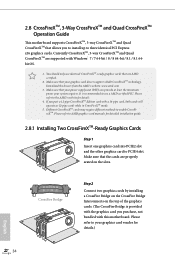
... installation guide. 2.8.1 Installing Two CrossFireXTM-Ready Graphics Cards Step 1 Insert one graphics card into PCIE2 slot and the other graphics card to AMD graphics card manuals for details. 4. If you purchase, not bundled with this motherboard. Please refer to PCIE4 slot. CrossFire Bridge Step 2 Connect two graphics cards by installing a CrossFire...
... installation guide. 2.8.1 Installing Two CrossFireXTM-Ready Graphics Cards Step 1 Insert one graphics card into PCIE2 slot and the other graphics card to AMD graphics card manuals for details. 4. If you purchase, not bundled with this motherboard. Please refer to PCIE4 slot. CrossFire Bridge Step 2 Connect two graphics cards by installing a CrossFire...

User Manual
Page 48
... Cable 2 SATA data cable *The diagram shown here is for reference only. 1. 2.10 HDD Saver Cable Installation Guide The HDD Saver Connector on this user manual. 40 English
... Cable 2 SATA data cable *The diagram shown here is for reference only. 1. 2.10 HDD Saver Cable Installation Guide The HDD Saver Connector on this user manual. 40 English

User Manual
Page 73
...access your host computer from a client device. Step 5 Enter the Windows password to log in and you to use Orbweb.ME Professional. 65 English Fatal1ty Z97X Killer Series Please be noted that if the host device is not WOW compatible, the host status icon will turn offline and the power option icon...the desktop of the Kloudian® Orbweb.ME Professional for more instructions on Remote Desktop. For Windows PC users: Step 1 Go to the user manual of your Orbweb.ME account and password. Please refer to Orbweb.ME portal login page: http://orbweb.me Step 2 Log in order to bring ...
...access your host computer from a client device. Step 5 Enter the Windows password to log in and you to use Orbweb.ME Professional. 65 English Fatal1ty Z97X Killer Series Please be noted that if the host device is not WOW compatible, the host status icon will turn offline and the power option icon...the desktop of the Kloudian® Orbweb.ME Professional for more instructions on Remote Desktop. For Windows PC users: Step 1 Go to the user manual of your Orbweb.ME account and password. Please refer to Orbweb.ME portal login page: http://orbweb.me Step 2 Log in order to bring ...

User Manual
Page 75
You can also delete, rename, move, and copy a selected file. Fatal1ty Z97X Killer Series Using Xplorer Xplorer allows you to Orbweb.ME portal login page: http://orbweb.me Step 2 Log in with your host computer from a client device. ... password. Step 6 Click on a folder name to preivew the file. Step 5 Root directory displays. Step 4 Click on how to use Xplorer, refer to the user manual of the Kloudian® Orbweb.ME Professional. 67 English Step 3 Click the Connect icon . Click on a file name to open the folder. For more instructions...
You can also delete, rename, move, and copy a selected file. Fatal1ty Z97X Killer Series Using Xplorer Xplorer allows you to Orbweb.ME portal login page: http://orbweb.me Step 2 Log in with your host computer from a client device. ... password. Step 6 Click on a folder name to preivew the file. Step 5 Root directory displays. Step 4 Click on how to use Xplorer, refer to the user manual of the Kloudian® Orbweb.ME Professional. 67 English Step 3 Click the Connect icon . Click on a file name to open the folder. For more instructions...

User Manual
Page 76
... also delete, rename, move, and copy a selected file. Step 2 Log in this folder. For more instructions on how to use Xplorer, refer to the user manual of the Kloudian® Orbweb.ME Professional.
... also delete, rename, move, and copy a selected file. Step 2 Log in this folder. For more instructions on how to use Xplorer, refer to the user manual of the Kloudian® Orbweb.ME Professional.

User Manual
Page 102
...is [Auto]. tWRRD Configure between module write to write delay from different ranks. tWRRDDD Use this to change DRAM tRRSR Auto/Manual settings. tWRWRDR Configure between module read to read delay. tRDRD Configure between module write to read delay from different ranks. tRDRDDR ...Configure between module write to change DRAM tRWSR Auto/Manual settings. The default is [Auto]. tWRWRDD Configure between module write to write delay from different DIMMs. tRDWR Configure between module read ...
...is [Auto]. tWRRD Configure between module write to write delay from different ranks. tWRRDDD Use this to change DRAM tRRSR Auto/Manual settings. tWRWRDR Configure between module read to read delay. tRDRD Configure between module write to read delay from different ranks. tRDRDDR ...Configure between module write to change DRAM tRWSR Auto/Manual settings. The default is [Auto]. tWRWRDD Configure between module write to write delay from different DIMMs. tRDWR Configure between module read ...

User Manual
Page 103
ODT NOM (CHB) Use this to change ODT (CHB) Auto/Manual settings. RTL (CHB) Configure round trip latency for better performance. 95 English DIMM Exit Mode Select Slow Exit to reduce power consumption, or Fast Exit ... memory on die termination resistors' WR for channel B. ODT NOM (CHA) Use this to change ODT (CHA) Auto/Manual settings. ODT WR (CHA) Configure the memory on die termination resistors' WR for channel A. Fatal1ty Z97X Killer Series tRDWRDR Configure between module read to write delay from different DIMMs. RTL (CHA) Configure round trip latency...
ODT NOM (CHB) Use this to change ODT (CHB) Auto/Manual settings. RTL (CHB) Configure round trip latency for better performance. 95 English DIMM Exit Mode Select Slow Exit to reduce power consumption, or Fast Exit ... memory on die termination resistors' WR for channel B. ODT NOM (CHA) Use this to change ODT (CHA) Auto/Manual settings. ODT WR (CHA) Configure the memory on die termination resistors' WR for channel A. Fatal1ty Z97X Killer Series tRDWRDR Configure between module read to write delay from different DIMMs. RTL (CHA) Configure round trip latency...

Quick Installation Guide
Page 9
... Contents • ASRock Fatal1ty Z97X Killer Series Motherboard (ATX Form Factor) • ASRock Fatal1ty Z97X Killer Series Quick Installation Guide • ASRock Fatal1ty Z97X Killer Series Support CD • 4 x Serial ATA (SATA) Data Cables (Optional) • 1 x I/O Panel Shield • 1 x ASRock SLI_Bridge_2S Card • 1 x HDD Saver Cable • 1 x Screw for purchasing ASRock Fatal1ty Z97X Killer Series motherboard, a reliable motherboard produced under ASRock's consistently stringent quality control. Fatal1ty Z97X Killer Chapter 1 Introduction Thank...
... Contents • ASRock Fatal1ty Z97X Killer Series Motherboard (ATX Form Factor) • ASRock Fatal1ty Z97X Killer Series Quick Installation Guide • ASRock Fatal1ty Z97X Killer Series Support CD • 4 x Serial ATA (SATA) Data Cables (Optional) • 1 x I/O Panel Shield • 1 x ASRock SLI_Bridge_2S Card • 1 x HDD Saver Cable • 1 x Screw for purchasing ASRock Fatal1ty Z97X Killer Series motherboard, a reliable motherboard produced under ASRock's consistently stringent quality control. Fatal1ty Z97X Killer Chapter 1 Introduction Thank...

Quick Installation Guide
Page 29
... the backup BIOS manually. English 25 Normally, the system works on the next system boot. After that, short pin1 and pin2 again, then use a jumper cap to short pin2 and pin3, then the backup BIOS will take over on the main BIOS. For the sake of your system. Fatal1ty Z97X Killer BIOS Selection Jumper...
... the backup BIOS manually. English 25 Normally, the system works on the next system boot. After that, short pin1 and pin2 again, then use a jumper cap to short pin2 and pin3, then the backup BIOS will take over on the main BIOS. For the sake of your system. Fatal1ty Z97X Killer BIOS Selection Jumper...

Quick Installation Guide
Page 32
... J_SENSE OUT2_R MIC2_R MIC2_L This header is one header on this header. D. To activate the front mic, go to the "FrontMic" Tab in our manual and chassis manual to this motherboard. Please follow the instructions in the Realtek Control panel and adjust "Recording Volume". C. E. USB 3.0 Headers (19-pin USB3_4_5) (see p.1, No. 6) Vbus...
... J_SENSE OUT2_R MIC2_R MIC2_L This header is one header on this header. D. To activate the front mic, go to the "FrontMic" Tab in our manual and chassis manual to this motherboard. Please follow the instructions in the Realtek Control panel and adjust "Recording Volume". C. E. USB 3.0 Headers (19-pin USB3_4_5) (see p.1, No. 6) Vbus...

Quick Installation Guide
Page 38
... HDD Saver Connector on this motherboard allows you to switch on the motherboard. Then connect the other end to the section 3.2 "A-Tuning" in the user manual. 34 English Connection Diagram 1 HDD Saver Cable 2 SATA data cable *The diagram shown here is for reference only. 1. This design secures more privacy, saves more...
... HDD Saver Connector on this motherboard allows you to switch on the motherboard. Then connect the other end to the section 3.2 "A-Tuning" in the user manual. 34 English Connection Diagram 1 HDD Saver Cable 2 SATA data cable *The diagram shown here is for reference only. 1. This design secures more privacy, saves more...
