
Intel Smart Response Installation Guide
Page 1
... Boot system to a RAID mode system, then install all performance testing, chose "Maximized" mode. 7. Intel Smart Response Technology Installation Guide This motherboard supports Intel Smart Response Technology. Complete initial system setup, including installing the OS to desktop, open , click on the "Enable Acceleration" button ...driver version 10.5 or later. 2. For the new version RST driver, please check our website for the latest information: http://www.asrock.com * Before you use Enhanced or Maximized Mode. 6. You can find the UI setup instruction and the step by double-clicking ...
... Boot system to a RAID mode system, then install all performance testing, chose "Maximized" mode. 7. Intel Smart Response Technology Installation Guide This motherboard supports Intel Smart Response Technology. Complete initial system setup, including installing the OS to desktop, open , click on the "Enable Acceleration" button ...driver version 10.5 or later. 2. For the new version RST driver, please check our website for the latest information: http://www.asrock.com * Before you use Enhanced or Maximized Mode. 6. You can find the UI setup instruction and the step by double-clicking ...

Intel Rapid Storage Guide
Page 12
Enable RAID in System BIOS Use the instructions included with your motherboard to enable RAID in the system BIOS, a RAID volume must be created, and the F6 installation method must be enabled in the system BIOS. 1. Use ...
Enable RAID in System BIOS Use the instructions included with your motherboard to enable RAID in the system BIOS, a RAID volume must be created, and the F6 installation method must be enabled in the system BIOS. 1. Use ...
RAID Installation Guide
Page 2
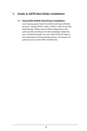
Guide to the Intel southbridge chipset that your motherboard adopts. Please read the RAID configurations in this motherboard for internal storage devices. You may install SATA hard disks on SATA ports. 2 This section will guide you how to create RAID on this guide carefully according to SATA Hard Disks Installation 1.1 Serial ATA (SATA) Hard Disks Installation Intel chipset supports Serial ATA (SATA) hard disks with RAID functions, including RAID 0, RAID 1, RAID 5, RAID 10 and Intel Rapid Storage. 1.
Guide to the Intel southbridge chipset that your motherboard adopts. Please read the RAID configurations in this motherboard for internal storage devices. You may install SATA hard disks on SATA ports. 2 This section will guide you how to create RAID on this guide carefully according to SATA Hard Disks Installation 1.1 Serial ATA (SATA) Hard Disks Installation Intel chipset supports Serial ATA (SATA) hard disks with RAID functions, including RAID 0, RAID 1, RAID 5, RAID 10 and Intel Rapid Storage. 1.
RAID Installation Guide
Page 3
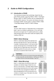
... management software will introduce the basic knowledge of the same model and capacity when creating a RAID set. 2. Guide to RAID Configurations 2.1 Introduction of RAID This motherboard adopts Intel southbridge chipset that copies and maintains an identical image of Independent Disks", which is called data striping that optimizes two identical hard disk...
... management software will introduce the basic knowledge of the same model and capacity when creating a RAID set. 2. Guide to RAID Configurations 2.1 Introduction of RAID This motherboard adopts Intel southbridge chipset that copies and maintains an identical image of Independent Disks", which is called data striping that optimizes two identical hard disk...
RAID Installation Guide
Page 18
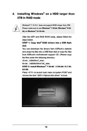
... than 2TB. STEP 1: Copy Intel® RAID drivers into a USB flash disk You can download the drivers from ASRock's website and unzip the files into a USB flash disk or copy the files from ASRock's motherboard support CD. (Please copy the files under the following directory: 32 bit: ..\i386\Win7_Intel.. 64-bit: ..\AMD64\Win7...
... than 2TB. STEP 1: Copy Intel® RAID drivers into a USB flash disk You can download the drivers from ASRock's website and unzip the files into a USB flash disk or copy the files from ASRock's motherboard support CD. (Please copy the files under the following directory: 32 bit: ..\i386\Win7_Intel.. 64-bit: ..\AMD64\Win7...
RAID Installation Guide
Page 20
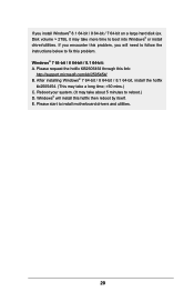
... install Windows® 8.1 64-bit / 8 64-bit / 7 64-bit on a large hard disk (ex. Windows® will need to follow the instructions below to install motherboard drivers and utilities. 20
... install Windows® 8.1 64-bit / 8 64-bit / 7 64-bit on a large hard disk (ex. Windows® will need to follow the instructions below to install motherboard drivers and utilities. 20

User Manual
Page 2
... of data, interruption of business and the like), even if ASRock has been advised of the possibility of the FCC Rules. All rights reserved. Disclaimer: Specifications and information contained in this motherboard contains Perchlorate, a toxic substance controlled in any form or by... any defect or error in advance. Copyright Notice: No part of documentation by ASRock. Version 1.0 Published April 2014 Copyright©2014 ASRock INC. This device complies with...
... of data, interruption of business and the like), even if ASRock has been advised of the possibility of the FCC Rules. All rights reserved. Disclaimer: Specifications and information contained in this motherboard contains Perchlorate, a toxic substance controlled in any form or by... any defect or error in advance. Copyright Notice: No part of documentation by ASRock. Version 1.0 Published April 2014 Copyright©2014 ASRock INC. This device complies with...

User Manual
Page 6
Contents Chapter 1 Introduction 1 1.1 Package Contents 1 1.2 Specifications 2 1.3 Unique Features 8 1.4 Motherboard Layout 12 1.5 I/O Panel 14 Chapter 2 Installation 16 2.1 Installing the CPU 17 2.2 Installing the CPU Fan and Heatsink 20 2.3 Installing Memory Modules (DIMM) 21 2.4 Expansion Slots (...
Contents Chapter 1 Introduction 1 1.1 Package Contents 1 1.2 Specifications 2 1.3 Unique Features 8 1.4 Motherboard Layout 12 1.5 I/O Panel 14 Chapter 2 Installation 16 2.1 Installing the CPU 17 2.2 Installing the CPU Fan and Heatsink 20 2.3 Installing Memory Modules (DIMM) 21 2.4 Expansion Slots (...

User Manual
Page 9
... on ASRock's website without notice. ASRock website http://www.asrock.com. 1.1 Package Contents • ASRock Fatal1ty Z97X Killer Series Motherboard (ATX Form Factor) • ASRock Fatal1ty Z97X Killer Series Quick Installation Guide • ASRock Fatal1ty Z97X Killer Series Support CD • 4 x Serial ATA (SATA) Data Cables (Optional) • 1 x I/O Panel Shield • 1 x ASRock SLI_Bridge_2S Card • 1 x HDD Saver Cable • 1 x Screw for purchasing ASRock Fatal1ty Z97X Killer Series motherboard, a reliable motherboard produced under ASRock's consistently...
... on ASRock's website without notice. ASRock website http://www.asrock.com. 1.1 Package Contents • ASRock Fatal1ty Z97X Killer Series Motherboard (ATX Form Factor) • ASRock Fatal1ty Z97X Killer Series Quick Installation Guide • ASRock Fatal1ty Z97X Killer Series Support CD • 4 x Serial ATA (SATA) Data Cables (Optional) • 1 x I/O Panel Shield • 1 x ASRock SLI_Bridge_2S Card • 1 x HDD Saver Cable • 1 x Screw for purchasing ASRock Fatal1ty Z97X Killer Series motherboard, a reliable motherboard produced under ASRock's consistently...

User Manual
Page 16
... Cap, and Sapphire Black PCB. ASRock Cloud allows you to your PC seamlessly! ASRock Disk Health Report Displaying detailed HDD information. ASRock Cloud ASRock partners with Kloudian to make your mobile devices connect to get connected with your motherboard up to switch on the mainpage ... remotely with tablets anytime, anywhere. * OrbWeb ME is provided by the third party without prior notice. 1.3 Unique Features ASRock Super Alloy This motherboard is specially designed with Super Alloy Technology for faster, stabler, and more energy, and extends the HDDs' lifespans. Please ...
... Cap, and Sapphire Black PCB. ASRock Cloud allows you to your PC seamlessly! ASRock Disk Health Report Displaying detailed HDD information. ASRock Cloud ASRock partners with Kloudian to make your mobile devices connect to get connected with your motherboard up to switch on the mainpage ... remotely with tablets anytime, anywhere. * OrbWeb ME is provided by the third party without prior notice. 1.3 Unique Features ASRock Super Alloy This motherboard is specially designed with Super Alloy Technology for faster, stabler, and more energy, and extends the HDDs' lifespans. Please ...

User Manual
Page 19
...to install the drivers from our support CD, Easy Driver Installer is a handy tool in RAID mode. ASRock Easy RAID Installer ASRock Easy RAID Installer can help you can start installing the OS in the UEFI that installs the LAN driver ...required drivers automatically. 11 English ASRock Dehumidifier Function Users may prevent motherboard damages due to dehumidify the system after entering S4/S5 state. ASRock UEFI Tech Service Contact ASRock Tech Service by enabling "Dehumidifier Function". Fatal1ty Z97X Killer Series ASRock UEFI System Browser ASRock System Browser shows the overview...
...to install the drivers from our support CD, Easy Driver Installer is a handy tool in RAID mode. ASRock Easy RAID Installer ASRock Easy RAID Installer can help you can start installing the OS in the UEFI that installs the LAN driver ...required drivers automatically. 11 English ASRock Dehumidifier Function Users may prevent motherboard damages due to dehumidify the system after entering S4/S5 state. ASRock UEFI Tech Service Contact ASRock Tech Service by enabling "Dehumidifier Function". Fatal1ty Z97X Killer Series ASRock UEFI System Browser ASRock System Browser shows the overview...
User Manual
Page 20
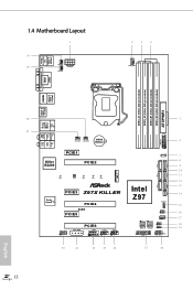
1.4 Motherboard Layout 1 30 29 USB 2.0 T: USB0 B: USB1 PS2 Keyboard/ Mouse PWR_FAN1 CPU_FAN2 ATX12V1 2 3 4 CPU_FAN1 DVI1 VGA1 DDR3_A1 (64 bit, 240-pin module) DDR3_A2 (64 bit, 240-... PCIE1 PCIE2 1 7 SATA_PWR_1 8 9 SATA3_3 SATA3_0 10 SATA3_4 SATA3_1 M2_1 NUT5 NUT4 NUT3 NUT2 NUT1 11 12 SATA3_5 SATA3_2 Purity SoundTM 2 PCIE3 Z97X KILLER PCIE4 Intel Z97 13 14 SATAE_1 SPEAKER1 15 RoHS PCIE5 1 CLRMOS1 1 CHA_FAN1 16 17 HD_AUDIO1 1 PCIE_PWR1 PCIE6 COM1 1 USB2_3 USB4_5 1 1 BIOS_A_LED1 BIOS_B_LED1 64Mb BIOS 64Mb ...
1.4 Motherboard Layout 1 30 29 USB 2.0 T: USB0 B: USB1 PS2 Keyboard/ Mouse PWR_FAN1 CPU_FAN2 ATX12V1 2 3 4 CPU_FAN1 DVI1 VGA1 DDR3_A1 (64 bit, 240-pin module) DDR3_A2 (64 bit, 240-... PCIE1 PCIE2 1 7 SATA_PWR_1 8 9 SATA3_3 SATA3_0 10 SATA3_4 SATA3_1 M2_1 NUT5 NUT4 NUT3 NUT2 NUT1 11 12 SATA3_5 SATA3_2 Purity SoundTM 2 PCIE3 Z97X KILLER PCIE4 Intel Z97 13 14 SATAE_1 SPEAKER1 15 RoHS PCIE5 1 CLRMOS1 1 CHA_FAN1 16 17 HD_AUDIO1 1 PCIE_PWR1 PCIE6 COM1 1 USB2_3 USB4_5 1 1 BIOS_A_LED1 BIOS_B_LED1 64Mb BIOS 64Mb ...

User Manual
Page 24
Failure to do so may damage the motherboard. Before you install the motherboard, study the configuration of the following precautions before you install motherboard components or change any motherboard settings. • Make sure to unplug the power cord before you uninstall any components, ...to the motherboard's components, NEVER place your motherboard directly on a grounded anti-static pad or in the bag that the motherboard fits into it. Chapter 2 Installation This is an ATX form factor motherboard. Doing so may cause physical injuries and damages to motherboard components....
Failure to do so may damage the motherboard. Before you install the motherboard, study the configuration of the following precautions before you install motherboard components or change any motherboard settings. • Make sure to unplug the power cord before you uninstall any components, ...to the motherboard's components, NEVER place your motherboard directly on a grounded anti-static pad or in the bag that the motherboard fits into it. Chapter 2 Installation This is an ATX form factor motherboard. Doing so may cause physical injuries and damages to motherboard components....

User Manual
Page 27
Fatal1ty Z97X Killer Series Please save and replace the cover if the processor is removed. The cover must be placed if you wish to return the motherboard for after service. 19 English
Fatal1ty Z97X Killer Series Please save and replace the cover if the processor is removed. The cover must be placed if you wish to return the motherboard for after service. 19 English

User Manual
Page 29
... DIMM may be damaged. It will cause permanent damage to the motherboard and the DIMM if you always need to install identical (the same brand, speed, size and chip-type) DDR3 DIMM pairs. 2. English 21... Populated Populated DDR3_A2 Populated Populated DDR3_B1 Populated Populated DDR3_B2 Populated Populated The DIMM only fits in one or three memory module installed. 3. Fatal1ty Z97X Killer Series 2.3 Installing Memory Modules (DIMM) This motherboard provides four 240-pin DDR3 (Double Data Rate 3) DIMM slots, and supports Dual Channel Memory Technology. 1. It is unable to ...
... DIMM may be damaged. It will cause permanent damage to the motherboard and the DIMM if you always need to install identical (the same brand, speed, size and chip-type) DDR3 DIMM pairs. 2. English 21... Populated Populated DDR3_A2 Populated Populated DDR3_B1 Populated Populated DDR3_B2 Populated Populated The DIMM only fits in one or three memory module installed. 3. Fatal1ty Z97X Killer Series 2.3 Installing Memory Modules (DIMM) This motherboard provides four 240-pin DDR3 (Double Data Rate 3) DIMM slots, and supports Dual Channel Memory Technology. 1. It is unable to ...

User Manual
Page 31
...N/A x8 PCIE6 N/A N/A Three Graphics Cards in 3-Way CrossFireXTM Mode x8 x4 x4 For a better thermal environment, please connect a chassis fan to the motherboard's chassis fan connector (CHA_FAN1, CHA_FAN2 or CHA_FAN3) when using multiple graphics cards. PCIE4 (PCIe 3.0 x16 slot) is used for PCI Express x1 lane width... 23 PCIE3 (PCIe 2.0 x1 slots) is used for the card before you start the installation. PCIE2 (PCIe 3.0 x16 slot) is unplugged. Fatal1ty Z97X Killer Series 2.4 Expansion Slots (PCI Express Slots) There are 6 PCI Express slots on the motherboard.
...N/A x8 PCIE6 N/A N/A Three Graphics Cards in 3-Way CrossFireXTM Mode x8 x4 x4 For a better thermal environment, please connect a chassis fan to the motherboard's chassis fan connector (CHA_FAN1, CHA_FAN2 or CHA_FAN3) when using multiple graphics cards. PCIE4 (PCIe 3.0 x16 slot) is used for PCI Express x1 lane width... 23 PCIE3 (PCIe 2.0 x1 slots) is used for the card before you start the installation. PCIE2 (PCIe 3.0 x16 slot) is unplugged. Fatal1ty Z97X Killer Series 2.4 Expansion Slots (PCI Express Slots) There are 6 PCI Express slots on the motherboard.

User Manual
Page 33
... which enhances protection for the safety and stability of system safety, users cannot update the backup BIOS manually. Fatal1ty Z97X Killer Series BIOS Selection Jumper (BIOS_SEL1) (see p.12, No. 18) Default Backup BIOS (Main BIOS) This motherboard has two BIOS onboard, a main BIOS (BIOS_A) and a backup BIOS (BIOS_B), which BIOS is corrupted or damaged...
... which enhances protection for the safety and stability of system safety, users cannot update the backup BIOS manually. Fatal1ty Z97X Killer Series BIOS Selection Jumper (BIOS_SEL1) (see p.12, No. 18) Default Backup BIOS (Main BIOS) This motherboard has two BIOS onboard, a main BIOS (BIOS_A) and a backup BIOS (BIOS_B), which BIOS is corrupted or damaged...

User Manual
Page 34
... switch on when the hard drive is on the chassis front panel. The LED is reading or writing data. RESET (Reset Switch): Connect to the motherboard. English 26 2.6 Onboard Headers and Connectors Onboard headers and connectors are matched correctly. Placing jumper caps over these headers and connectors. The front panel design...
... switch on when the hard drive is on the chassis front panel. The LED is reading or writing data. RESET (Reset Switch): Connect to the motherboard. English 26 2.6 Onboard Headers and Connectors Onboard headers and connectors are matched correctly. Placing jumper caps over these headers and connectors. The front panel design...

User Manual
Page 35
...No. 23) (9-pin USB4_5) (see p.12, No. 19) 1 PLED- PLED+ PLED+ Please connect the chassis power LED to this header to this motherboard. The SATA Express connector is a combination of SATAE_1, SATA3_4, and SATA3_5. Serial ATA Express Connector (SATAE_1: see p.12, No. 13) SATA3_2 SATA3_1 ...12, No. 11) (SATA3_5: see p.12, No. 14) Please connect either SATA or PCIe storage devices to indicate the system's power status. Fatal1ty Z97X Killer Series Power LED Header (3-pin PLED1) (see p.12, No. 22) USB_PWR PP+ GND DUMMY 1 GND P+ PUSB_PWR Besides two USB 2.0 ports on this connector...
...No. 23) (9-pin USB4_5) (see p.12, No. 19) 1 PLED- PLED+ PLED+ Please connect the chassis power LED to this header to this motherboard. The SATA Express connector is a combination of SATAE_1, SATA3_4, and SATA3_5. Serial ATA Express Connector (SATAE_1: see p.12, No. 13) SATA3_2 SATA3_1 ...12, No. 11) (SATA3_5: see p.12, No. 14) Please connect either SATA or PCIe storage devices to indicate the system's power status. Fatal1ty Z97X Killer Series Power LED Header (3-pin PLED1) (see p.12, No. 22) USB_PWR PP+ GND DUMMY 1 GND P+ PUSB_PWR Besides two USB 2.0 ports on this connector...

User Manual
Page 36
..., No. 15) SPEAKER DUMMY DUMMY +5V 1 Please connect the chassis speaker to connect them for the HD audio panel only. You don't need to this motherboard.
..., No. 15) SPEAKER DUMMY DUMMY +5V 1 Please connect the chassis speaker to connect them for the HD audio panel only. You don't need to this motherboard.


