
Intel Smart Response Installation Guide
Page 1
... tray, lower right-hand corner of the screen. 4. For the new version RST driver, please check our website for the latest information: http://www.asrock.com * Before you use the full SSD as Cache device or only 20GB, and if you want to a RAID mode system, then install all ..." mode. 7. UI setup instruction: 1. Once open RST GUI from either Start Menu or by step instructions below. Intel Smart Response Technology Installation Guide This motherboard supports Intel Smart Response Technology. Boot system to desktop, open , click on the "Enable Acceleration" button on the GUI panel. 5.
... tray, lower right-hand corner of the screen. 4. For the new version RST driver, please check our website for the latest information: http://www.asrock.com * Before you use the full SSD as Cache device or only 20GB, and if you want to a RAID mode system, then install all ..." mode. 7. UI setup instruction: 1. Once open RST GUI from either Start Menu or by step instructions below. Intel Smart Response Technology Installation Guide This motherboard supports Intel Smart Response Technology. Boot system to desktop, open , click on the "Enable Acceleration" button on the GUI panel. 5.
RAID Installation Guide
Page 2
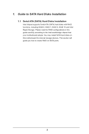
1. Guide to create RAID on this guide carefully according to the Intel southbridge chipset that your motherboard adopts. Please read the RAID configurations in this motherboard for internal storage devices. You may install SATA hard disks on SATA ports. 2 This section will guide you how to SATA Hard Disks Installation 1.1 Serial ATA (SATA) Hard Disks Installation Intel chipset supports Serial ATA (SATA) hard disks with RAID functions, including RAID 0, RAID 1, RAID 5, RAID 10 and Intel Rapid Storage.
1. Guide to create RAID on this guide carefully according to the Intel southbridge chipset that your motherboard adopts. Please read the RAID configurations in this motherboard for internal storage devices. You may install SATA hard disks on SATA ports. 2 This section will guide you how to SATA Hard Disks Installation 1.1 Serial ATA (SATA) Hard Disks Installation Intel chipset supports Serial ATA (SATA) hard disks with RAID functions, including RAID 0, RAID 1, RAID 5, RAID 10 and Intel Rapid Storage.
RAID Installation Guide
Page 3
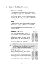
... read and write data in parallel, interleaved stacks. Although RAID 0 function can improve the access performance, it does not provide any HDDs of RAID This motherboard adopts Intel southbridge chipset that integrates RAID controller supporting RAID 0 / RAID 1/ Intel Rapid Storage / RAID 10 / RAID 5 function with four independent Serial ATA (SATA) channels...
... read and write data in parallel, interleaved stacks. Although RAID 0 function can improve the access performance, it does not provide any HDDs of RAID This motherboard adopts Intel southbridge chipset that integrates RAID controller supporting RAID 0 / RAID 1/ Intel Rapid Storage / RAID 10 / RAID 5 function with four independent Serial ATA (SATA) channels...
RAID Installation Guide
Page 18
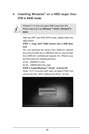
... boot. 18 STEP 1: Copy Intel® RAID drivers into a USB flash disk You can download the drivers from ASRock's website and unzip the files into a USB flash disk or copy the files from ASRock's motherboard support CD. (Please copy the files under the following directory: 32 bit: ..\i386\Win7_Intel.. 64-bit: ..\AMD64\Win7...
... boot. 18 STEP 1: Copy Intel® RAID drivers into a USB flash disk You can download the drivers from ASRock's website and unzip the files into a USB flash disk or copy the files from ASRock's motherboard support CD. (Please copy the files under the following directory: 32 bit: ..\i386\Win7_Intel.. 64-bit: ..\AMD64\Win7...
RAID Installation Guide
Page 20
... instructions below to reboot.) D. Please start to boot into Windows® or install driver/utilities. Reboot your system. (It may take more time to install motherboard drivers and utilities. 20 Disk volume > 2TB), it may take a long time; >30 mins.) C. Please request the hotfix KB2505454 through this hotfix then reboot by...
... instructions below to reboot.) D. Please start to boot into Windows® or install driver/utilities. Reboot your system. (It may take more time to install motherboard drivers and utilities. 20 Disk volume > 2TB), it may take a long time; >30 mins.) C. Please request the hotfix KB2505454 through this hotfix then reboot by...

Intel Rapid Storage Guide
Page 12
... volume. 1. Enable RAID in the system BIOS. 1. Switch the SATA Operation Mode option to enable RAID in System BIOS Use the instructions included with your motherboard to RAID. 5. Use the up or down arrow keys to select the RAID level and press Enter. 4.
... volume. 1. Enable RAID in the system BIOS. 1. Switch the SATA Operation Mode option to enable RAID in System BIOS Use the instructions included with your motherboard to RAID. 5. Use the up or down arrow keys to select the RAID level and press Enter. 4.
Quick Installation Guide
Page 1
... conditions: (1) this documentation may or may apply, see www.dtsc.ca.gov/hazardouswaste/ perchlorate" ASRock Website: http://www.asrock.com CALIFORNIA, USA ONLY The Lithium battery adopted on this motherboard contains Perchlorate, a toxic substance controlled in this documentation, ASRock does not provide warranty of any kind, either expressed or implied, including but not limited...
... conditions: (1) this documentation may or may apply, see www.dtsc.ca.gov/hazardouswaste/ perchlorate" ASRock Website: http://www.asrock.com CALIFORNIA, USA ONLY The Lithium battery adopted on this motherboard contains Perchlorate, a toxic substance controlled in this documentation, ASRock does not provide warranty of any kind, either expressed or implied, including but not limited...
Quick Installation Guide
Page 5
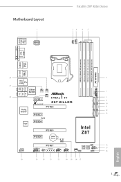
USB 2.0 T: USB0 B: USB1 PS2 Keyboard/ Mouse Motherboard Layout ATX12V1 Fatal1ty Z87 Killer Series CPU_FAN2 CPU_FAN1 DVI1 VGA1 DDR3_A1 (64 bit, 240-pin module) DDR3_A2 (64 bit, 240-pin module) DDR3_B1 (64 bit, ... CHA_FAN3 CHA_FAN2 Top: Center: SATA3_1 SATA3_0 SATA3_3 SATA3_2 Purity SoundTM PCIE1 X Fast LAN 1 FATA L PWR_FAN1 TY Z87 KILLER PCIE2 PCIE3 SATA3_5 SATA3_4 RoHS Super I/O PCIE4 PCIE5 Intel Z87 PCIE6 CMOS Battery BIOS_A_LED1 BIOS_B_LED1 CLRCMOS1 1 HD_AUDIO1 1 COM1 1 IR1 1 PCIE7 SLI/XFIRE_PWR1 USB6_7 1 USB4_5 1 CHA_FAN1 64Mb BIOS BIOS_A1 1 BIOS_SEL1 ...
USB 2.0 T: USB0 B: USB1 PS2 Keyboard/ Mouse Motherboard Layout ATX12V1 Fatal1ty Z87 Killer Series CPU_FAN2 CPU_FAN1 DVI1 VGA1 DDR3_A1 (64 bit, 240-pin module) DDR3_A2 (64 bit, 240-pin module) DDR3_B1 (64 bit, ... CHA_FAN3 CHA_FAN2 Top: Center: SATA3_1 SATA3_0 SATA3_3 SATA3_2 Purity SoundTM PCIE1 X Fast LAN 1 FATA L PWR_FAN1 TY Z87 KILLER PCIE2 PCIE3 SATA3_5 SATA3_4 RoHS Super I/O PCIE4 PCIE5 Intel Z87 PCIE6 CMOS Battery BIOS_A_LED1 BIOS_B_LED1 CLRCMOS1 1 HD_AUDIO1 1 COM1 1 IR1 1 PCIE7 SLI/XFIRE_PWR1 USB6_7 1 USB4_5 1 CHA_FAN1 64Mb BIOS BIOS_A1 1 BIOS_SEL1 ...
Quick Installation Guide
Page 9
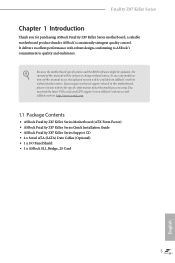
It delivers excellent performance with robust design conforming to ASRock's commitment to this motherboard, please visit our website for purchasing ASRock Fatal1ty Z87 Killer Series motherboard, a reliable motherboard produced under ASRock's consistently stringent quality control. ASRock website http://www.asrock.com. 1.1 Package Contents • ASRock Fatal1ty Z87 Killer Series Motherboard (ATX Form Factor) • ASRock Fatal1ty Z87 Killer Series Quick Installation Guide • ASRock Fatal1ty Z87 Killer Series Support CD • 4 x Serial ATA (SATA) Data...
It delivers excellent performance with robust design conforming to ASRock's commitment to this motherboard, please visit our website for purchasing ASRock Fatal1ty Z87 Killer Series motherboard, a reliable motherboard produced under ASRock's consistently stringent quality control. ASRock website http://www.asrock.com. 1.1 Package Contents • ASRock Fatal1ty Z87 Killer Series Motherboard (ATX Form Factor) • ASRock Fatal1ty Z87 Killer Series Quick Installation Guide • ASRock Fatal1ty Z87 Killer Series Support CD • 4 x Serial ATA (SATA) Data...
Quick Installation Guide
Page 16
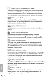
You may prevent motherboard damages due to dampness by enabling "Dehumidifier Function". ASRock UEFI System Browser ASRock System Browser shows the overview of your system via OMG. ASRock Easy RAID Installer ASRock Easy RAID Installer can start installing the OS in the UEFI that don't have an optical disk... drive to install the drivers from the support CD to other required drivers automatically. ASRock Internet Flash ASRock Internet Flash downloads and updates the latest UEFI firmware version from our servers for you to copy the RAID driver from...
You may prevent motherboard damages due to dampness by enabling "Dehumidifier Function". ASRock UEFI System Browser ASRock System Browser shows the overview of your system via OMG. ASRock Easy RAID Installer ASRock Easy RAID Installer can start installing the OS in the UEFI that don't have an optical disk... drive to install the drivers from the support CD to other required drivers automatically. ASRock Internet Flash ASRock Internet Flash downloads and updates the latest UEFI firmware version from our servers for you to copy the RAID driver from...
Quick Installation Guide
Page 18
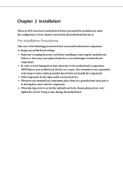
...pad or in the bag that the motherboard fits into it. Doing so may cause physical injuries to you install the motherboard, study the configuration of the following precautions before you uninstall any motherboard settings. • Make sure to the motherboard's components, NEVER place your chassis ...use a grounded wrist strap or touch a safety grounded object before installing or removing the motherboard. Failure to do so may damage the motherboard. Before you and damages to motherboard components. • In order to avoid damage from static electricity to unplug the power cord...
...pad or in the bag that the motherboard fits into it. Doing so may cause physical injuries to you install the motherboard, study the configuration of the following precautions before you uninstall any motherboard settings. • Make sure to the motherboard's components, NEVER place your chassis ...use a grounded wrist strap or touch a safety grounded object before installing or removing the motherboard. Failure to do so may damage the motherboard. Before you and damages to motherboard components. • In order to avoid damage from static electricity to unplug the power cord...

Quick Installation Guide
Page 21
Fatal1ty Z87 Killer Series Please save and replace the cover if the processor is removed. The cover must be placed if you wish to return the motherboard for after service. 17 English
Fatal1ty Z87 Killer Series Please save and replace the cover if the processor is removed. The cover must be placed if you wish to return the motherboard for after service. 17 English
Quick Installation Guide
Page 23
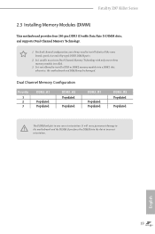
It will cause permanent damage to the motherboard and the DIMM if you always need to install identical (the same brand, speed, size and chip-type) DDR3 DIMM pairs. 2. For dual channel configuration, ... only fits in one or three memory module installed. 3. otherwise, this motherboard and DIMM may be damaged. English 19 It is not allowed to activate Dual Channel Memory Technology with only one correct orientation. Fatal1ty Z87 Killer Series 2.3 Installing Memory Modules (DIMM) This motherboard provides four 240-pin DDR3 (Double Data Rate 3) DIMM slots, and...
It will cause permanent damage to the motherboard and the DIMM if you always need to install identical (the same brand, speed, size and chip-type) DDR3 DIMM pairs. 2. For dual channel configuration, ... only fits in one or three memory module installed. 3. otherwise, this motherboard and DIMM may be damaged. English 19 It is not allowed to activate Dual Channel Memory Technology with only one correct orientation. Fatal1ty Z87 Killer Series 2.3 Installing Memory Modules (DIMM) This motherboard provides four 240-pin DDR3 (Double Data Rate 3) DIMM slots, and...

Quick Installation Guide
Page 25
... or SLITM Mode x8 x8 N/A Three Graphics Cards in 3-Way CrossFireXTM Mode x8 x4 x4 For a better thermal environment, please connect a chassis fan to the motherboard's chassis fan connector (CHA_FAN1, CHA_FAN2 or CHA_FAN3) when using multiple graphics cards. PCIE2 (PCIe 3.0 x16 slot) is used for PCI Express x1 lane width cards... (PCIe 3.0 x16 slot) is used for PCI Express x1 lane width cards. PCIE3 (PCIe 2.0 x1 slots) is used for PCI Express x1 lane width cards. Fatal1ty Z87 Killer Series 2.4 Expansion Slots (PCI Express Slots) There are 7 PCI Express slots on the motherboard.
... or SLITM Mode x8 x8 N/A Three Graphics Cards in 3-Way CrossFireXTM Mode x8 x4 x4 For a better thermal environment, please connect a chassis fan to the motherboard's chassis fan connector (CHA_FAN1, CHA_FAN2 or CHA_FAN3) when using multiple graphics cards. PCIE2 (PCIe 3.0 x16 slot) is used for PCI Express x1 lane width cards... (PCIe 3.0 x16 slot) is used for PCI Express x1 lane width cards. PCIE3 (PCIe 2.0 x1 slots) is used for PCI Express x1 lane width cards. Fatal1ty Z87 Killer Series 2.4 Expansion Slots (PCI Express Slots) There are 7 PCI Express slots on the motherboard.
Quick Installation Guide
Page 27
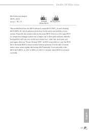
... protection for the safety and stability of system safety, users cannot update the backup BIOS manually. English 23 Fatal1ty Z87 Killer Series BIOS Selection Jumper (BIOS_SEL1) (see p.1, No. 17) Default Backup BIOS (Main BIOS) This motherboard has two BIOS onboard, a main BIOS (BIOS_A) and a backup BIOS (BIOS_B), which BIOS is corrupted or damaged, please...
... protection for the safety and stability of system safety, users cannot update the backup BIOS manually. English 23 Fatal1ty Z87 Killer Series BIOS Selection Jumper (BIOS_SEL1) (see p.1, No. 17) Default Backup BIOS (Main BIOS) This motherboard has two BIOS onboard, a main BIOS (BIOS_A) and a backup BIOS (BIOS_B), which BIOS is corrupted or damaged, please...
Quick Installation Guide
Page 28
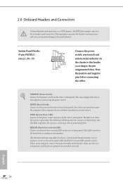
... the system is on the chassis front panel. The LED is in S4 sleep state or powered off your chassis front panel module to the motherboard. When connecting your system using the power switch. PWRBTN (Power Switch): Connect to perform a normal restart. 2.6 Onboard Headers and Connectors Onboard headers and connectors are...
... the system is on the chassis front panel. The LED is in S4 sleep state or powered off your chassis front panel module to the motherboard. When connecting your system using the power switch. PWRBTN (Power Switch): Connect to perform a normal restart. 2.6 Onboard Headers and Connectors Onboard headers and connectors are...
Quick Installation Guide
Page 29
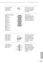
... 1 GND P+ PUSB_PWR Besides four USB 2.0 ports on the I /O panel, there is one header on this motherboard. Each USB 2.0 header can support two ports. Fatal1ty Z87 Killer Series Power LED Header (3-pin PLED1) (see p.1, No. 12) SATA3_5 SATA3_3 SATA3_1 SATA3_4 SATA3_2 SATA3_0 Please connect ... IntA_PB_SSTXIntA_PB_SSTX+ GND IntA_PB_DIntA_PB_D+ Dummy 1 Besides four USB 3.0 ports on the I /O panel, there are two headers on this motherboard. English 25 These six SATA3 connectors support SATA data cables for internal storage devices with up to indicate the system's power status...
... 1 GND P+ PUSB_PWR Besides four USB 2.0 ports on the I /O panel, there is one header on this motherboard. Each USB 2.0 header can support two ports. Fatal1ty Z87 Killer Series Power LED Header (3-pin PLED1) (see p.1, No. 12) SATA3_5 SATA3_3 SATA3_1 SATA3_4 SATA3_2 SATA3_0 Please connect ... IntA_PB_SSTXIntA_PB_SSTX+ GND IntA_PB_DIntA_PB_D+ Dummy 1 Besides four USB 3.0 ports on the I /O panel, there are two headers on this motherboard. English 25 These six SATA3 connectors support SATA data cables for internal storage devices with up to indicate the system's power status...
Quick Installation Guide
Page 31
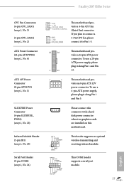
Fatal1ty Z87 Killer Series CPU Fan Connectors (4-pin CPU_FAN1) (see p.1, No. 3) (3-pin CPU_FAN2) (see p.1, No. 2)...pin IR1) (see p.1, No. 23) Serial Port Header (9-pin COM1) (see p.1, No. 24) GND +12V CPU_FAN_SPEED FAN_SPEED_CONTROL This motherboard provides a 4-Pin CPU fan (Quiet Fan) connector. To use a 20-pin ATX power supply, please plug it along Pin 1... If you plan to connect a 3-Pin CPU fan, please connect it along Pin 1 and Pin 13. 8 5 This motherboard pro- This COM1 header supports a serial port module. 27 English vides an 8-pin ATX 12V 4 1 power connector. Please...
Fatal1ty Z87 Killer Series CPU Fan Connectors (4-pin CPU_FAN1) (see p.1, No. 3) (3-pin CPU_FAN2) (see p.1, No. 2)...pin IR1) (see p.1, No. 23) Serial Port Header (9-pin COM1) (see p.1, No. 24) GND +12V CPU_FAN_SPEED FAN_SPEED_CONTROL This motherboard provides a 4-Pin CPU fan (Quiet Fan) connector. To use a 20-pin ATX power supply, please plug it along Pin 1... If you plan to connect a 3-Pin CPU fan, please connect it along Pin 1 and Pin 13. 8 5 This motherboard pro- This COM1 header supports a serial port module. 27 English vides an 8-pin ATX 12V 4 1 power connector. Please...


