
Intel Smart Response Installation Guide
Page 1
... GUI will refresh to accelerate AND the SSD in the near future. You MUST have both the HDD you intend to show the newly accelerated system configuration. * Intel® will update the new version RST driver in system at this point! 3. Intel Smart Response Technology Installation Guide This motherboard supports Intel Smart Response Technology. UI setup instruction: 1. For all required drivers, including RST storage driver version 10.5 or later. 2.
... GUI will refresh to accelerate AND the SSD in the near future. You MUST have both the HDD you intend to show the newly accelerated system configuration. * Intel® will update the new version RST driver in system at this point! 3. Intel Smart Response Technology Installation Guide This motherboard supports Intel Smart Response Technology. UI setup instruction: 1. For all required drivers, including RST storage driver version 10.5 or later. 2.
Intel Rapid Storage Guide
Page 13
... if you see a message in the status line that says, Please insert the disk labeled Manufacturer-supplied hardware support disk into Drive A:, insert ;a floppy disk containing the following steps to confirm your controller and continue. Press S to install a third party SCSI or RAID driver. Use the Floppy Configuration Utility to create the volume. 9. Press Enter to create a floppy disk with a screen asking you have successfully installed the driver and Windows setup should continue.
... if you see a message in the status line that says, Please insert the disk labeled Manufacturer-supplied hardware support disk into Drive A:, insert ;a floppy disk containing the following steps to confirm your controller and continue. Press S to install a third party SCSI or RAID driver. Use the Floppy Configuration Utility to create the volume. 9. Press Enter to create a floppy disk with a screen asking you have successfully installed the driver and Windows setup should continue.

Intel Rapid Storage Guide
Page 16
... in RAID mode or AHCI mode, the F6 installation method must be prompted with the necessary files. Setup will happen immediately after pressing F6. Nothing will Note temporarily continue loading drivers. Press F6 when you see a prompt that says, Please insert the disk labeled Manufacturer-supplied hardware support disk into Drive A:, insert a floppy disk containing the following steps to install the Intel® Rapid Storage Technology driver using F6 when in AHCI/RAID mode...
... in RAID mode or AHCI mode, the F6 installation method must be prompted with the necessary files. Setup will happen immediately after pressing F6. Nothing will Note temporarily continue loading drivers. Press F6 when you see a prompt that says, Please insert the disk labeled Manufacturer-supplied hardware support disk into Drive A:, insert a floppy disk containing the following steps to install the Intel® Rapid Storage Technology driver using F6 when in AHCI/RAID mode...

RAID Installation Guide
Page 7
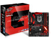
... the BIOS before setting your RAID configuration. Plug in your system, and press key to enter BIOS setup utility. STEP 1: Setting the BIOS RAID Items After installing the hard disk drives, please set SATA Mode Selection to [RAID]. Boot your USB flash drive into a USB port B. Please note that this document for all models A. STEP 4: Install Windows® 10 64-bit / 8.1 64-bit / 8 64-bit / 7 / 7 64-bit OS on how to set RAID configuration. STEP 2: Use ASRock Easy RAID Installer Easy RAID Installer can copy the RAID driver from a support CD to your USB storage device with RAID...
... the BIOS before setting your RAID configuration. Plug in your system, and press key to enter BIOS setup utility. STEP 1: Setting the BIOS RAID Items After installing the hard disk drives, please set SATA Mode Selection to [RAID]. Boot your USB flash drive into a USB port B. Please note that this document for all models A. STEP 4: Install Windows® 10 64-bit / 8.1 64-bit / 8 64-bit / 7 / 7 64-bit OS on how to set RAID configuration. STEP 2: Use ASRock Easy RAID Installer Easy RAID Installer can copy the RAID driver from a support CD to your USB storage device with RAID...
User Manual
Page 9
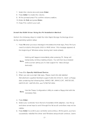
... Installation Guide • ASRock Fatal1ty Z270 Gaming K4 Series Support CD • 1 x I/O Panel Shield • 4 x Serial ATA (SATA) Data Cables (Optional) • 3 x Screws for specific information about the model you are using. You may find the latest VGA cards and CPU support list on ASRock's website without notice. In this documentation, Chapter 1 and 2 contains the introduction of the BIOS setup. Chapter 4 contains the configuration guide of the motherboard and step-by-step installation guides. In case any modifications of the software and utilities...
... Installation Guide • ASRock Fatal1ty Z270 Gaming K4 Series Support CD • 1 x I/O Panel Shield • 4 x Serial ATA (SATA) Data Cables (Optional) • 3 x Screws for specific information about the model you are using. You may find the latest VGA cards and CPU support list on ASRock's website without notice. In this documentation, Chapter 1 and 2 contains the introduction of the BIOS setup. Chapter 4 contains the configuration guide of the motherboard and step-by-step installation guides. In case any modifications of the software and utilities...
User Manual
Page 11
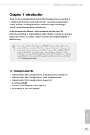
... 1920x1200 @ 60Hz • Supports D-Sub with max. Fatal1ty Z270 Gaming K4 Series Graphics • Intel® HD Graphics Built-in Visuals and the VGA outputs can be supported only with processors which are GPU integrated. • Supports Intel® HD Graphics Built-in Visuals : Intel® Quick Sync Video with max. GPU/SWEncode/ Decode: VP9, HEVC 10b (For 6th Gen Intel® CPU) • Max. resolution up to...
... 1920x1200 @ 60Hz • Supports D-Sub with max. Fatal1ty Z270 Gaming K4 Series Graphics • Intel® HD Graphics Built-in Visuals and the VGA outputs can be supported only with processors which are GPU integrated. • Supports Intel® HD Graphics Built-in Visuals : Intel® Quick Sync Video with max. GPU/SWEncode/ Decode: VP9, HEVC 10b (For 6th Gen Intel® CPU) • Max. resolution up to...
User Manual
Page 13
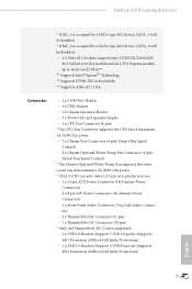
... Z270 Gaming K4 Series * If M2_1 is occupied by a SATA-type M.2 device, SATA_5 will be disabled. * If M2_2 is occupied by a SATA-type M.2 device, SATA_0 will be disabled. • 2 x Ultra M.2 Sockets, support type 2230/2242/2260/2280 M.2 SATA3 6.0 Gb/s module and M.2 PCI Express module up to Gen3 x4 (32 Gb/s)** ** Supports Intel® OptaneTM Technology ** Supports NVMe SSD as boot disks ** Supports ASRock U.2 Kit Connector • 1 x COM Port Header • 1 x TPM Header • 1 x Chassis Intrusion Header • 1 x Power LED and Speaker Header • 1 x CPU Fan Connector (4-pin...
... Z270 Gaming K4 Series * If M2_1 is occupied by a SATA-type M.2 device, SATA_5 will be disabled. * If M2_2 is occupied by a SATA-type M.2 device, SATA_0 will be disabled. • 2 x Ultra M.2 Sockets, support type 2230/2242/2260/2280 M.2 SATA3 6.0 Gb/s module and M.2 PCI Express module up to Gen3 x4 (32 Gb/s)** ** Supports Intel® OptaneTM Technology ** Supports NVMe SSD as boot disks ** Supports ASRock U.2 Kit Connector • 1 x COM Port Header • 1 x TPM Header • 1 x Chassis Intrusion Header • 1 x Power LED and Speaker Header • 1 x CPU Fan Connector (4-pin...

User Manual
Page 15
...-pin module) DDR4_B2 (64 bit, 288-pin module) 5 HDMI1 USB 3.0 T: USB3_TA_1 Top: B: USB3_TC_1 RJ-45 Center: REAR SPK Top: USB 3.0 T: USB1 B: USB2 CHA_FAN2 USB3_5_6 6 1 7 USB3_3_4 Central/Bass LINE IN Bottom: Optical SPDIF Top: Center: FRONT Bottom: MIC IN 26 LAN PCIE1 CT4 PCI Express 3.0 CT3 CT2 CT1 PCIE2 CLRMOS1 1 M2_2 RoHS 25 1 FATAL TY CMOS Battery AUDIO CODEC PCIE3 Z270 Gaming K4 Intel Z270 PCIE4 Ultra M.2 PCIe...
...-pin module) DDR4_B2 (64 bit, 288-pin module) 5 HDMI1 USB 3.0 T: USB3_TA_1 Top: B: USB3_TC_1 RJ-45 Center: REAR SPK Top: USB 3.0 T: USB1 B: USB2 CHA_FAN2 USB3_5_6 6 1 7 USB3_3_4 Central/Bass LINE IN Bottom: Optical SPDIF Top: Center: FRONT Bottom: MIC IN 26 LAN PCIE1 CT4 PCI Express 3.0 CT3 CT2 CT1 PCIE2 CLRMOS1 1 M2_2 RoHS 25 1 FATAL TY CMOS Battery AUDIO CODEC PCIE3 Z270 Gaming K4 Intel Z270 PCIE4 Ultra M.2 PCIe...

User Manual
Page 16
...) 10 SATA3 Connectors (SATA_0_1) 11 System Panel Header (PANEL1) 12 Power LED and Speaker Header (SPK_PLED1) 13 Chassis Fan / Waterpump Fan Connector (CHA_FAN3/W_PUMP) 14 Chassis Fan Connector (CHA_FAN1) 15 USB 2.0 Header (USB_3_4) 16 USB 2.0 Header (USB_5_6) 17 USB 2.0 Header (USB_7) 18 AURA RGB LED Header (RGB_LED) 19 COM Port Header (COM1) 20 TPM Header (TPMS1) 21 Chassis Intrusion Header (CI1) 22 Front Panel Audio Header (HD_AUDIO1) 23 Thunderbolt AIC Connector (TB1) 24 Thunderbolt AIC Connector (TB2) 25 Clear CMOS Jumper (CLRMOS1) 26 Chassis Fan Connector (CHA_FAN2) 8 English...
...) 10 SATA3 Connectors (SATA_0_1) 11 System Panel Header (PANEL1) 12 Power LED and Speaker Header (SPK_PLED1) 13 Chassis Fan / Waterpump Fan Connector (CHA_FAN3/W_PUMP) 14 Chassis Fan Connector (CHA_FAN1) 15 USB 2.0 Header (USB_3_4) 16 USB 2.0 Header (USB_5_6) 17 USB 2.0 Header (USB_7) 18 AURA RGB LED Header (RGB_LED) 19 COM Port Header (COM1) 20 TPM Header (TPMS1) 21 Chassis Intrusion Header (CI1) 22 Front Panel Audio Header (HD_AUDIO1) 23 Thunderbolt AIC Connector (TB1) 24 Thunderbolt AIC Connector (TB2) 25 Clear CMOS Jumper (CLRMOS1) 26 Chassis Fan Connector (CHA_FAN2) 8 English...

User Manual
Page 27
... that the password, date, time, and user default profile will be detected. When the jumper cap is removed. However, please do the clear-CMOS action. Please adjust the BIOS option "Clear Status" to default setup, please turn off the computer and unplug the power cord from the power supply. If you update the BIOS. English 19 To clear and reset the system parameters to clear the record of previous chassis intrusion status...
... that the password, date, time, and user default profile will be detected. When the jumper cap is removed. However, please do the clear-CMOS action. Please adjust the BIOS option "Clear Status" to default setup, please turn off the computer and unplug the power cord from the power supply. If you update the BIOS. English 19 To clear and reset the system parameters to clear the record of previous chassis intrusion status...

User Manual
Page 29
.... 10) SATA_0 SATA_2 SATA_4 SPEAKER DUMMY DUMMY +5V 1 PLED+ PLED+ PLED- Each USB 3.0 header can support two ports. 21 English Please connect the chassis power LED and the chassis speaker to 6.0 Gb/s data transfer rate. * If M2_1 is occupied by a SATA-type M.2 device, SATA_5 will be disabled. * If M2_2 is occupied by a SATA-type M.2 device, SATA_0 will be disabled. Fatal1ty Z270 Gaming K4 Series Power LED and Speaker Header (7-pin SPK_PLED1) (see p.7, No. 12) Serial ATA3 Connectors (SATA_4_5: see p.7, No. 8) (SATA_2_3...
.... 10) SATA_0 SATA_2 SATA_4 SPEAKER DUMMY DUMMY +5V 1 PLED+ PLED+ PLED- Each USB 3.0 header can support two ports. 21 English Please connect the chassis power LED and the chassis speaker to 6.0 Gb/s data transfer rate. * If M2_1 is occupied by a SATA-type M.2 device, SATA_5 will be disabled. * If M2_2 is occupied by a SATA-type M.2 device, SATA_0 will be disabled. Fatal1ty Z270 Gaming K4 Series Power LED and Speaker Header (7-pin SPK_PLED1) (see p.7, No. 12) Serial ATA3 Connectors (SATA_4_5: see p.7, No. 8) (SATA_2_3...
User Manual
Page 31
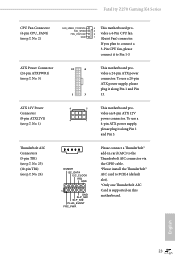
Fatal1ty Z270 Gaming K4 Series CPU Fan Connector (4-pin CPU_FAN1) (see p.7, No. 1) 8 5 This motherboard pro- ATX 12V Power Connector (8-pin ATX12V1) (see p.7, No. 2) FAN_SPEED_CONTROL FAN_SPEED FAN_VOLTAGE GND 4 This motherboard pro- 3 2 vides a 4-Pin CPU fan 1 (Quiet Fan) connector. vides an 8-pin ATX 12V power connector. Thunderbolt AIC Connectors (5-pin TB1) (see p.7, No. 23) (10-pin TB2) (see p.7, No. 5) 12 24 1 13 This motherboard provides a 24-pin ATX power connector. To use a 20-pin ATX power supply, please plug it along Pin 1 and Pin 13. To use a ...
Fatal1ty Z270 Gaming K4 Series CPU Fan Connector (4-pin CPU_FAN1) (see p.7, No. 1) 8 5 This motherboard pro- ATX 12V Power Connector (8-pin ATX12V1) (see p.7, No. 2) FAN_SPEED_CONTROL FAN_SPEED FAN_VOLTAGE GND 4 This motherboard pro- 3 2 vides a 4-Pin CPU fan 1 (Quiet Fan) connector. vides an 8-pin ATX 12V power connector. Thunderbolt AIC Connectors (5-pin TB1) (see p.7, No. 23) (10-pin TB2) (see p.7, No. 5) 12 24 1 13 This motherboard provides a 24-pin ATX power connector. To use a 20-pin ATX power supply, please plug it along Pin 1 and Pin 13. To use a ...
User Manual
Page 33
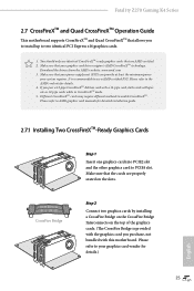
... slot. Fatal1ty Z270 Gaming K4 Series 2.7 CrossFireXTM and Quad CrossFireXTM Operation Guide This motherboard supports CrossFireXTM and Quad CrossFireXTM that your graphics card driver supports AMD CrossFireXTM technology. Download the drivers from the AMD's website: www.amd.com 3. Make sure that are properly seated on the top of the graphics cards. (The CrossFire Bridge is recommended to your system requires. Please refer to AMD graphics card manuals for detailed installation guide. 2.7.1 Installing Two CrossFireXTM-Ready Graphics Cards Step 1 Insert one graphics card...
... slot. Fatal1ty Z270 Gaming K4 Series 2.7 CrossFireXTM and Quad CrossFireXTM Operation Guide This motherboard supports CrossFireXTM and Quad CrossFireXTM that your graphics card driver supports AMD CrossFireXTM technology. Download the drivers from the AMD's website: www.amd.com 3. Make sure that are properly seated on the top of the graphics cards. (The CrossFire Bridge is recommended to your system requires. Please refer to AMD graphics card manuals for detailed installation guide. 2.7.1 Installing Two CrossFireXTM-Ready Graphics Cards Step 1 Insert one graphics card...
User Manual
Page 35
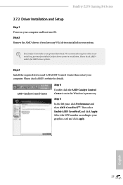
Fatal1ty Z270 Gaming K4 Series 2.7.2 Driver Installation and Setup Step 1 Power on your computer. Step 2 Remove the AMD drivers if you have any previously installed Catalyst drivers prior to your system. Please check AMD's website for details. Please check AMD's website for AMD driver updates. AMD Catalyst Control Center Step 4 Double-click the AMD Catalyst Control Center icon in your graphics card and click Apply. Step 5 In the left pane, click Performance and then AMD CrossFireXTM. Select...
Fatal1ty Z270 Gaming K4 Series 2.7.2 Driver Installation and Setup Step 1 Power on your computer. Step 2 Remove the AMD drivers if you have any previously installed Catalyst drivers prior to your system. Please check AMD's website for details. Please check AMD's website for AMD driver updates. AMD Catalyst Control Center Step 4 Double-click the AMD Catalyst Control Center icon in your graphics card and click Apply. Step 5 In the left pane, click Performance and then AMD CrossFireXTM. Select...
User Manual
Page 41
... improve Windows 7 compatibility, please download and install the following hot fix provided by Microsoft. Please click Install All or follow the installation wizard to install those required drivers. Therefore, the drivers you install can work properly. Fatal1ty Z270 Gaming K4 Series Chapter 3 Software and Utilities Operation 3.1 Installing Drivers The Support CD that comes with the motherboard contains necessary drivers and useful utilities that the motherboard supports. If the Main Menu does not appear automatically, locate and double click on the file...
... improve Windows 7 compatibility, please download and install the following hot fix provided by Microsoft. Please click Install All or follow the installation wizard to install those required drivers. Therefore, the drivers you install can work properly. Fatal1ty Z270 Gaming K4 Series Chapter 3 Software and Utilities Operation 3.1 Installing Drivers The Support CD that comes with the motherboard contains necessary drivers and useful utilities that the motherboard supports. If the Main Menu does not appear automatically, locate and double click on the file...

User Manual
Page 72
... a redirection table, which is installed. Select enable to one or more local APICs. Onboard LAN Enable or disable the onboard network interface controller. 64 English PCIE6 Link Speed Select the link speed for PCIE5. PCIE ASPM Support This option enables/disables the ASPM support for all CPU downstream devices. Share Memory Configure the size of the DMI Link. IGPU Multi-Monitor Select disable to disable the integrated graphics when an external graphics card is used to route the interrupts...
... a redirection table, which is installed. Select enable to one or more local APICs. Onboard LAN Enable or disable the onboard network interface controller. 64 English PCIE6 Link Speed Select the link speed for PCIE5. PCIE ASPM Support This option enables/disables the ASPM support for all CPU downstream devices. Share Memory Configure the size of the DMI Link. IGPU Multi-Monitor Select disable to disable the integrated graphics when an external graphics card is used to route the interrupts...
User Manual
Page 81
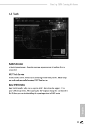
Please setup network configuration before using UEFI Tech Service. Easy RAID Installer Easy RAID Installer helps you to copy the RAID driver from the support CD to RAID, then you are having trouble with your USB storage device. After copying the drivers please change the SATA mode to your PC. UEFI Tech Service Contact ASRock Tech Service if you can start installing the operating system in RAID mode. 73 English 4.7 Tools Fatal1ty Z270 Gaming K4 Series System Browser ASRock System Browser shows the overview of your current PC and the devices connected.
Please setup network configuration before using UEFI Tech Service. Easy RAID Installer Easy RAID Installer helps you to copy the RAID driver from the support CD to RAID, then you are having trouble with your USB storage device. After copying the drivers please change the SATA mode to your PC. UEFI Tech Service Contact ASRock Tech Service if you can start installing the operating system in RAID mode. 73 English 4.7 Tools Fatal1ty Z270 Gaming K4 Series System Browser ASRock System Browser shows the overview of your current PC and the devices connected.
User Manual
Page 82
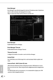
... (Auto IP), Auto ASRock Internet Flash downloads and updates the latest UEFI firmware version from our servers for the Boot Manager. Instant Flash Save UEFI files in your USB storage device and run Instant Flash to plug in your UEFI. Boot Manager Timeout Enable/disable the Boot Manager Timeout. Please setup network configuration before using Internet Flash. *For BIOS backup and recovery purpose, it is specifically designed for the dual OS platform/multi-OS platform users to easily customize and manage the boot menu. *Please connect...
... (Auto IP), Auto ASRock Internet Flash downloads and updates the latest UEFI firmware version from our servers for the Boot Manager. Instant Flash Save UEFI files in your USB storage device and run Instant Flash to plug in your UEFI. Boot Manager Timeout Enable/disable the Boot Manager Timeout. Please setup network configuration before using Internet Flash. *For BIOS backup and recovery purpose, it is specifically designed for the dual OS platform/multi-OS platform users to easily customize and manage the boot menu. *Please connect...

User Manual
Page 83
UEFI Download Server Select a server to configure internet connection settings for Internet Flash. Fatal1ty Z270 Gaming K4 Series Network Configuration Use this to download the UEFI firmware. 75 English Internet Setting Enable or disable sound effects in the setup utility.
UEFI Download Server Select a server to configure internet connection settings for Internet Flash. Fatal1ty Z270 Gaming K4 Series Network Configuration Use this to download the UEFI firmware. 75 English Internet Setting Enable or disable sound effects in the setup utility.

User Manual
Page 87
... Trust Technology Enable/disable Intel PTT in the UEFI Setup Utility. Supervisor Password Set or change the settings in the UEFI Setup Utility. Only the administrator has authority to remove the password. Leave it blank and press enter to change the password for Windows 8.1 Secure Boot. Leave it blank and press enter to use discrete TPM Module. 79 English You may set or change the password for the system. Secure Boot Use this option to remove the password. Fatal1ty Z270 Gaming K4 Series 4.9 Security Screen In...
... Trust Technology Enable/disable Intel PTT in the UEFI Setup Utility. Supervisor Password Set or change the settings in the UEFI Setup Utility. Only the administrator has authority to remove the password. Leave it blank and press enter to change the password for Windows 8.1 Secure Boot. Leave it blank and press enter to use discrete TPM Module. 79 English You may set or change the password for the system. Secure Boot Use this option to remove the password. Fatal1ty Z270 Gaming K4 Series 4.9 Security Screen In...


