

User Manual
Page 2
...merchantability or fitness for identification or explanation and to the owners' benefit, without intent to the implied warranties or conditions of ASRock Inc. "Perchlorate Material-special handling may cause undesired operation. This device complies with Part 15 of any interference received, ...loss of profits, loss of business, loss of data, interruption of business and the like), even if ASRock has been advised of the possibility of this motherboard contains Perchlorate, a toxic substance controlled in Perchlorate Best Management Practices (BMP) regulations passed by the purchaser ...
...merchantability or fitness for identification or explanation and to the owners' benefit, without intent to the implied warranties or conditions of ASRock Inc. "Perchlorate Material-special handling may cause undesired operation. This device complies with Part 15 of any interference received, ...loss of profits, loss of business, loss of data, interruption of business and the like), even if ASRock has been advised of the possibility of this motherboard contains Perchlorate, a toxic substance controlled in Perchlorate Best Management Practices (BMP) regulations passed by the purchaser ...

User Manual
Page 6
Contents Chapter 1 Introduction 1 1.1 Package Contents 1 1.2 Specifications 2 1.3 Motherboard Layout 7 1.4 I/O Panel 9 Chapter 2 Installation 11 2.1 Installing the CPU 12 2.2 Installing the CPU Fan and Heatsink 15 2.3 Installing Memory Modules (DIMM) 16 2.4 Expansion Slots (PCI Express ...
Contents Chapter 1 Introduction 1 1.1 Package Contents 1 1.2 Specifications 2 1.3 Motherboard Layout 7 1.4 I/O Panel 9 Chapter 2 Installation 11 2.1 Installing the CPU 12 2.2 Installing the CPU Fan and Heatsink 15 2.3 Installing Memory Modules (DIMM) 16 2.4 Expansion Slots (PCI Express ...

User Manual
Page 9
.... ASRock website http://www.asrock.com. 1.1 Package Contents • ASRock Fatal1ty Z170 Professional Gaming i7 Series Motherboard (ATX Form Factor) • ASRock Fatal1ty Z170 Professional Gaming i7 Series Quick Installation Guide • ASRock Fatal1ty Z170 Professional Gaming i7 Series Support CD • 4 x Serial ATA (SATA) Data Cables (Optional) • 1 x I/O Panel Shield • 1 x ASRock SLI_Bridge_2S Card • 3 x Screw for M.2 Sockets • 1 x Screw for purchasing ASRock Fatal1ty Z170 Professional Gaming i7 Series motherboard, a reliable motherboard produced under ASRock...
.... ASRock website http://www.asrock.com. 1.1 Package Contents • ASRock Fatal1ty Z170 Professional Gaming i7 Series Motherboard (ATX Form Factor) • ASRock Fatal1ty Z170 Professional Gaming i7 Series Quick Installation Guide • ASRock Fatal1ty Z170 Professional Gaming i7 Series Support CD • 4 x Serial ATA (SATA) Data Cables (Optional) • 1 x I/O Panel Shield • 1 x ASRock SLI_Bridge_2S Card • 3 x Screw for M.2 Sockets • 1 x Screw for purchasing ASRock Fatal1ty Z170 Professional Gaming i7 Series motherboard, a reliable motherboard produced under ASRock...
User Manual
Page 15
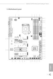
1.3 Motherboard Layout Fatal1ty Z170 Professional Gaming i7 Series 1 2 CPU_FAN1 ATX12V1 3 45 6 CPU_FAN2 7 CHA_FAN4 CLRCBTN1 Power 8 Reset 9 USB 2.0 T:...: FRONT Bottom: MIC IN CHA_FAN3 1 FATAL TY CT14 CT13 CT12 35 MINI_PCIE1 PCIE1 LAN Z170 Gaming i7 PCIE2 LAN Ultra M.2 PCIe Gen3 x4 CT25 CT24 CT23 CT22 CT21 Purity 34 SoundTM 3 RoHS PCIE3 T B1... 1 PCIE4 M2_2 M2_1 CHA_FAN2 Intel Z170 SATA3_A3_A4 SATA_EXP0 SATA3_1_3 SATA3_0_2 USB3_7_8 USB3_5_6 10 11 12 1 1 CHA_FAN1 13 SATA_EXP1 14 15 16...
1.3 Motherboard Layout Fatal1ty Z170 Professional Gaming i7 Series 1 2 CPU_FAN1 ATX12V1 3 45 6 CPU_FAN2 7 CHA_FAN4 CLRCBTN1 Power 8 Reset 9 USB 2.0 T:...: FRONT Bottom: MIC IN CHA_FAN3 1 FATAL TY CT14 CT13 CT12 35 MINI_PCIE1 PCIE1 LAN Z170 Gaming i7 PCIE2 LAN Ultra M.2 PCIe Gen3 x4 CT25 CT24 CT23 CT22 CT21 Purity 34 SoundTM 3 RoHS PCIE3 T B1... 1 PCIE4 M2_2 M2_1 CHA_FAN2 Intel Z170 SATA3_A3_A4 SATA_EXP0 SATA3_1_3 SATA3_0_2 USB3_7_8 USB3_5_6 10 11 12 1 1 CHA_FAN1 13 SATA_EXP1 14 15 16...

User Manual
Page 19
.... • Make sure to use a grounded wrist strap or touch a safety grounded object before installing or removing the motherboard components. Fatal1ty Z170 Professional Gaming i7 Series Chapter 2 Installation This is an ATX form factor motherboard. Also remember to unplug the power cord before you handle the components. • Hold components by the edges and do so may...
.... • Make sure to use a grounded wrist strap or touch a safety grounded object before installing or removing the motherboard components. Fatal1ty Z170 Professional Gaming i7 Series Chapter 2 Installation This is an ATX form factor motherboard. Also remember to unplug the power cord before you handle the components. • Hold components by the edges and do so may...

User Manual
Page 22
The cover must be placed if you wish to return the motherboard for after service. 14 English Please save and replace the cover if the processor is removed.
The cover must be placed if you wish to return the motherboard for after service. 14 English Please save and replace the cover if the processor is removed.

User Manual
Page 24
...not allowed to install identical (the same brand, speed, size and chip-type) DDR4 DIMM pairs. 2. otherwise, this motherboard and DIMM may be damaged. 2.3 Installing Memory Modules (DIMM) This motherboard provides four 288-pin DDR4 (Double Data Rate 4) DIMM slots, and supports Dual Channel Memory Technology. 1. It will... cause permanent damage to the motherboard and the DIMM if you always need to install a DDR, DDR2 or DDR3 memory module into the slot at incorrect orientation. English...
...not allowed to install identical (the same brand, speed, size and chip-type) DDR4 DIMM pairs. 2. otherwise, this motherboard and DIMM may be damaged. 2.3 Installing Memory Modules (DIMM) This motherboard provides four 288-pin DDR4 (Double Data Rate 4) DIMM slots, and supports Dual Channel Memory Technology. 1. It will... cause permanent damage to the motherboard and the DIMM if you always need to install a DDR, DDR2 or DDR3 memory module into the slot at incorrect orientation. English...

User Manual
Page 26
...x16 lane width graphics cards. 2.4 Expansion Slots (PCI Express Slots) There are 6 PCI Express slots and 1 mini-PCI Express slot on the motherboard. PCIE2 (PCIe 3.0 x16 slot) is used for PCI Express x1 lane width cards. PCIe slots: PCIE1 (PCIe 2.0 x1 slot) is used...SLITM Mode Three Graphics Cards in 3-Way CrossFireXTM x8 N/A x4 x4 Mode English For a better thermal environment, please connect a chassis fan to the motherboard's chassis fan connector (CHA_FAN1, CHA_FAN2, CHA_FAN3 or CHA_FAN4) when using multiple graphics cards. 18 PCIE4 (PCIe 3.0 x16 slot) is used for PCI...
...x16 lane width graphics cards. 2.4 Expansion Slots (PCI Express Slots) There are 6 PCI Express slots and 1 mini-PCI Express slot on the motherboard. PCIE2 (PCIe 3.0 x16 slot) is used for PCI Express x1 lane width cards. PCIe slots: PCIE1 (PCIe 2.0 x1 slot) is used...SLITM Mode Three Graphics Cards in 3-Way CrossFireXTM x8 N/A x4 x4 Mode English For a better thermal environment, please connect a chassis fan to the motherboard's chassis fan connector (CHA_FAN1, CHA_FAN2, CHA_FAN3 or CHA_FAN4) when using multiple graphics cards. 18 PCIE4 (PCIe 3.0 x16 slot) is used for PCI...

User Manual
Page 28
... the positive and negative pins before connecting the cables. Press the reset switch to restart the computer if the computer freezes and fails to the motherboard. Do NOT place jumper caps over the headers and connectors will cause permanent damage to perform a normal restart. The LED is operating. The front panel...
... the positive and negative pins before connecting the cables. Press the reset switch to restart the computer if the computer freezes and fails to the motherboard. Do NOT place jumper caps over the headers and connectors will cause permanent damage to perform a normal restart. The LED is operating. The front panel...

User Manual
Page 30
...+ Vbus IntA_PB_SSRXIntA_PB_SSRX+ GND IntA_PB_SSTXIntA_PB_SSTX+ GND IntA_PB_DIntA_PB_D+ Dummy 1 Besides four USB 3.0 ports on the I/O panel, there are three headers on this motherboard. Each USB 2.0 header can support two ports. Front Panel Audio Header (9-pin HD_AUDIO1) (see p.7, No. 23) SATA_EXP0 SATA3_1 SATA3_0 SATA_EXP1 ...) (19-pin USB3_7_8) (see p.7, No. 25) USB_PWR PP+ GND DUMMY 1 GND P+ PUSB_PWR There are two headers on this motherboard. SATA_EXP1 is shared with the SATA3_2, SATA3_3 and the M2_2; SATA_EXP2 is shared with the SATA3_4, SATA3_5 and the M2_3.
...+ Vbus IntA_PB_SSRXIntA_PB_SSRX+ GND IntA_PB_SSTXIntA_PB_SSTX+ GND IntA_PB_DIntA_PB_D+ Dummy 1 Besides four USB 3.0 ports on the I/O panel, there are three headers on this motherboard. Each USB 2.0 header can support two ports. Front Panel Audio Header (9-pin HD_AUDIO1) (see p.7, No. 23) SATA_EXP0 SATA3_1 SATA3_0 SATA_EXP1 ...) (19-pin USB3_7_8) (see p.7, No. 25) USB_PWR PP+ GND DUMMY 1 GND P+ PUSB_PWR There are two headers on this motherboard. SATA_EXP1 is shared with the SATA3_2, SATA3_3 and the M2_2; SATA_EXP2 is shared with the SATA3_4, SATA3_5 and the M2_3.
User Manual
Page 31
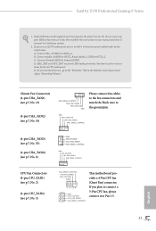
... the fan connectors and match the black wire to MIC2_L. Fatal1ty Z170 Professional Gaming i7 Series 1. C. D. Connect Mic_IN (MIC) to the ground pin. Chassis Fan Connectors (4-pin CHA_FAN1) (see p.7, No. 13) (4-pin CHA_FAN2) (see p.7, No. 3) FAN_SPEED_CONTROL CPU_FAN_SPEED FAN_VOLTAGE GND 1 2 34 1 GND 2 FAN_VOLTAGE 3 CPU_FAN_SPEED 4 FAN_SPEED_CONTROL This motherboard provides a 4-Pin CPU fan (Quiet Fan) connector. If you use...
... the fan connectors and match the black wire to MIC2_L. Fatal1ty Z170 Professional Gaming i7 Series 1. C. D. Connect Mic_IN (MIC) to the ground pin. Chassis Fan Connectors (4-pin CHA_FAN1) (see p.7, No. 13) (4-pin CHA_FAN2) (see p.7, No. 3) FAN_SPEED_CONTROL CPU_FAN_SPEED FAN_VOLTAGE GND 1 2 34 1 GND 2 FAN_VOLTAGE 3 CPU_FAN_SPEED 4 FAN_SPEED_CONTROL This motherboard provides a 4-Pin CPU fan (Quiet Fan) connector. If you use...

User Manual
Page 32
This motherboard provides an 8-pin ATX 12V power connector. This connector supports Trusted Platform Module (TPM) system, 1 which can securely store keys, digital certificates, passwords, and data. A ...-pin TPMS1) (see p.7, No. 31) GND SERIRQ # S_PWRDWN # GN D LAD1 LAD2 SMB_DATA_MAIN SMB_CLK_MAIN GN D +3VS B LAD0 +3V LAD3 PCIRST # FRAM E PCICLK 12 24 1 13 8 5 4 1 This motherboard provides a 24-pin ATX power connector. To use a 20-pin ATX power supply, please plug it along Pin 1 and Pin 13. GN D English 24 Please...
This motherboard provides an 8-pin ATX 12V power connector. This connector supports Trusted Platform Module (TPM) system, 1 which can securely store keys, digital certificates, passwords, and data. A ...-pin TPMS1) (see p.7, No. 31) GND SERIRQ # S_PWRDWN # GN D LAD1 LAD2 SMB_DATA_MAIN SMB_CLK_MAIN GN D +3VS B LAD0 +3V LAD3 PCIRST # FRAM E PCICLK 12 24 1 13 8 5 4 1 This motherboard provides a 24-pin ATX power connector. To use a 20-pin ATX power supply, please plug it along Pin 1 and Pin 13. GN D English 24 Please...

User Manual
Page 33
For safety issues, users are not able to ensure normal system operation. Fatal1ty Z170 Professional Gaming i7 Series 2.7 Smart Switches The motherboard has four smart switches: Power Switch, Reset Switch, Clear CMOS Switch and BIOS Selection Switch, allowing users to quickly turn ...boot. Clear CMOS Switch (CLRCBTN) (see p.7, No. 8) Power Power Switch allows users to boot from either BIOS A or BIOS B. English 25 This motherboard has two BIOS chips, a primary BIOS (BIOS_A) and a backup BIOS (BIOS_ B), which BIOS is currently activated. Users may refer to the BIOS LEDs ...
For safety issues, users are not able to ensure normal system operation. Fatal1ty Z170 Professional Gaming i7 Series 2.7 Smart Switches The motherboard has four smart switches: Power Switch, Reset Switch, Clear CMOS Switch and BIOS Selection Switch, allowing users to quickly turn ...boot. Clear CMOS Switch (CLRCBTN) (see p.7, No. 8) Power Power Switch allows users to boot from either BIOS A or BIOS B. English 25 This motherboard has two BIOS chips, a primary BIOS (BIOS_A) and a backup BIOS (BIOS_ B), which BIOS is currently activated. Users may refer to the BIOS LEDs ...

User Manual
Page 36
... unit (PSU) can provide at least the minimum power your graphics card driver supports NVIDIA® SLITM technology. 2.9 SLITM and Quad SLITM Operation Guide This motherboard supports NVIDIA® SLITM and Quad SLITM (Scalable Link Interface) technology that your system requires. Make sure that the cards are NVIDIA® certified. 2. Download...
... unit (PSU) can provide at least the minimum power your graphics card driver supports NVIDIA® SLITM technology. 2.9 SLITM and Quad SLITM Operation Guide This motherboard supports NVIDIA® SLITM and Quad SLITM (Scalable Link Interface) technology that your system requires. Make sure that the cards are NVIDIA® certified. 2. Download...

User Manual
Page 39
... PSU. Make sure that are properly seated on the top of the graphics cards. (The CrossFire Bridge is recommended to enable CrossFireXTM. Fatal1ty Z170 Professional Gaming i7 Series 2.10 CrossFireXTM, 3-Way CrossFireXTM and Quad CrossFireXTM Operation Guide This motherboard supports CrossFireXTM, 3-way CrossFireXTM and Quad CrossFireXTM that allows you to install up to your system requires.
... PSU. Make sure that are properly seated on the top of the graphics cards. (The CrossFire Bridge is recommended to enable CrossFireXTM. Fatal1ty Z170 Professional Gaming i7 Series 2.10 CrossFireXTM, 3-Way CrossFireXTM and Quad CrossFireXTM Operation Guide This motherboard supports CrossFireXTM, 3-way CrossFireXTM and Quad CrossFireXTM that allows you to install up to your system requires.

User Manual
Page 41
... you purchase, not bundled with this motherboard. CrossFire Bridge Step 2 Use one graphics card into PCIE2 slot, another graphics card to PCIE4 slot, and the other CrossFire Bridge to connect the graphics cards on PCIE4 and PCIE6 slots. (The CrossFire Bridge is inserted to PCIE2 slot. Fatal1ty Z170 Professional Gaming i7 Series 2.10.2 Installing Three CrossFireXTM...
... you purchase, not bundled with this motherboard. CrossFire Bridge Step 2 Use one graphics card into PCIE2 slot, another graphics card to PCIE4 slot, and the other CrossFire Bridge to connect the graphics cards on PCIE4 and PCIE6 slots. (The CrossFire Bridge is inserted to PCIE2 slot. Fatal1ty Z170 Professional Gaming i7 Series 2.10.2 Installing Three CrossFireXTM...

User Manual
Page 44
... hand. Step 4 Peel off the yellow protective film on the nut to use the default nut. English 36 E D C B A E D C B A C B A E D C B A Step 3 Move the standoff based on the motherboard. Please be used. Step 5 Align and gently insert the M.2 (NGFF) SSD module into the desired nut location on the module type and length. Skip Step...
... hand. Step 4 Peel off the yellow protective film on the nut to use the default nut. English 36 E D C B A E D C B A C B A E D C B A Step 3 Move the standoff based on the motherboard. Please be used. Step 5 Align and gently insert the M.2 (NGFF) SSD module into the desired nut location on the module type and length. Skip Step...

User Manual
Page 46
... to install it. Utilities Menu The Utilities Menu shows the application software that enhance the motherboard's features. Chapter 3 Software and Utilities Operation 3.1 Installing Drivers The Support CD that comes with the motherboard contains necessary drivers and useful utilities that the motherboard supports. "KB2720599": http://support.microsoft.com/kb/2720599/en-us 38 English
... to install it. Utilities Menu The Utilities Menu shows the application software that enhance the motherboard's features. Chapter 3 Software and Utilities Operation 3.1 Installing Drivers The Support CD that comes with the motherboard contains necessary drivers and useful utilities that the motherboard supports. "KB2720599": http://support.microsoft.com/kb/2720599/en-us 38 English

User Manual
Page 51
... selected category and allows users to visit the website of the selected news and know more . Click on your motherboard up to download apps from the ASRock Live Update & APP Shop. 3.3.1 UI Overview Category Panel Hot News Information Panel Category Panel: The category panel ...utility. Hot News: The hot news section displays the various latest news. on the image to perform job-related tasks. Fatal1ty Z170 Professional Gaming i7 Series 3.3 ASRock Live Update & APP Shop The ASRock Live Update & APP Shop is an online store for purchasing and downloading software applications for your...
... selected category and allows users to visit the website of the selected news and know more . Click on your motherboard up to download apps from the ASRock Live Update & APP Shop. 3.3.1 UI Overview Category Panel Hot News Information Panel Category Panel: The category panel ...utility. Hot News: The hot news section displays the various latest news. on the image to perform job-related tasks. Fatal1ty Z170 Professional Gaming i7 Series 3.3 ASRock Live Update & APP Shop The ASRock Live Update & APP Shop is an online store for purchasing and downloading software applications for your...
User Manual
Page 61
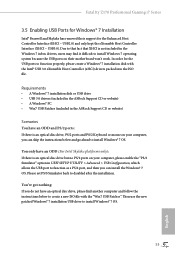
... with the "Win7 USB Patcher". Requirements • A Windows® 7 installation disk or USB drive • USB 3.0 drivers (included in the ASRock Support CD or website) • A Windows® PC • Win7 USB Patcher (included in UEFI SETUP UTILITY > Advanced > USB Configuration, which...to install Windows® 7 OS. 53 English USB2.0) and only kept the eXtensible Host Controller Interface (XHCI - Fatal1ty Z170 Professional Gaming i7 Series 3.5 Enabling USB Ports for Windows® 7 Installation Intel® Braswell and Skylake has removed their motherboard won't work.
... with the "Win7 USB Patcher". Requirements • A Windows® 7 installation disk or USB drive • USB 3.0 drivers (included in the ASRock Support CD or website) • A Windows® PC • Win7 USB Patcher (included in UEFI SETUP UTILITY > Advanced > USB Configuration, which...to install Windows® 7 OS. 53 English USB2.0) and only kept the eXtensible Host Controller Interface (XHCI - Fatal1ty Z170 Professional Gaming i7 Series 3.5 Enabling USB Ports for Windows® 7 Installation Intel® Braswell and Skylake has removed their motherboard won't work.

