
User Manual
Page 7
... Chapter 3 Software and Utilities Operation 42 3.1 Installing Drivers 42 3.2 F-Stream 43 3.3 Killer Network Manager 49 3.3.1 Installing Killer Network Manager 49 3.3.2 Using Killer Network Manager 49 3.4 ASRock Cloud (on Qualcomm® Atheros® KillerTM E2200 Series) 52 3.5 ASRock APP Shop 62 3.5.1 UI Overview 62 3.5.2 Apps 63 3.5.3 BIOS & Drivers 66 3.5.4 Setting 67 3.6 Start8 68 3.7 XSplit Broadcaster 71 3.7.1 Live...
... Chapter 3 Software and Utilities Operation 42 3.1 Installing Drivers 42 3.2 F-Stream 43 3.3 Killer Network Manager 49 3.3.1 Installing Killer Network Manager 49 3.3.2 Using Killer Network Manager 49 3.4 ASRock Cloud (on Qualcomm® Atheros® KillerTM E2200 Series) 52 3.5 ASRock APP Shop 62 3.5.1 UI Overview 62 3.5.2 Apps 63 3.5.3 BIOS & Drivers 66 3.5.4 Setting 67 3.6 Start8 68 3.7 XSplit Broadcaster 71 3.7.1 Live...
User Manual
Page 9
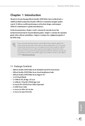
... to this documentation, Chapter 1 and 2 contains the introduction of the BIOS setup. Chapter 4 contains the configuration guide of the motherboard and step-by-step installation guides. ASRock website http://www.asrock.com. 1.1 Package Contents • ASRock Fatal1ty X99X Killer Series Motherboard (ATX Form Factor) • ASRock Fatal1ty X99X Killer Series Quick Installation Guide • ASRock Fatal1ty X99X Killer Series Support CD • 1 x I/O Panel Shield •...
... to this documentation, Chapter 1 and 2 contains the introduction of the BIOS setup. Chapter 4 contains the configuration guide of the motherboard and step-by-step installation guides. ASRock website http://www.asrock.com. 1.1 Package Contents • ASRock Fatal1ty X99X Killer Series Motherboard (ATX Form Factor) • ASRock Fatal1ty X99X Killer Series Quick Installation Guide • ASRock Fatal1ty X99X Killer Series Support CD • 1 x I/O Panel Shield •...

User Manual
Page 12
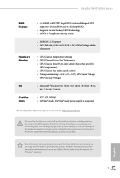
...Connectors, support RAID (RAID 0, RAID 1, RAID 5, RAID 10 and Intel Rapid Storage 13), NCQ, AHCI, Hot Plug and ASRock HDD Saver Technology (SSATA3_3 connector is shared with the eSATA port) (SSATA3_2 connector is shared with Ultra M.2 Socket) * RAID is...Thunderbolt AIC Connector • 2 x USB 2.0 Headers (support 4 USB 2.0 ports) (Supports ESD Protection (ASRock Full Spike Protection)) • 1 x Vertical Type A USB 2.0 • 2 x USB 3.0 Headers (Support 4 USB 3.0 ports) (Supports ESD Protection (ASRock Full Spike Protection)) • 1 x Dr. Debug with LED • 1 x Power Switch with LED...
...Connectors, support RAID (RAID 0, RAID 1, RAID 5, RAID 10 and Intel Rapid Storage 13), NCQ, AHCI, Hot Plug and ASRock HDD Saver Technology (SSATA3_3 connector is shared with the eSATA port) (SSATA3_2 connector is shared with Ultra M.2 Socket) * RAID is...Thunderbolt AIC Connector • 2 x USB 2.0 Headers (support 4 USB 2.0 ports) (Supports ESD Protection (ASRock Full Spike Protection)) • 1 x Vertical Type A USB 2.0 • 2 x USB 3.0 Headers (Support 4 USB 3.0 ports) (Supports ESD Protection (ASRock Full Spike Protection)) • 1 x Dr. Debug with LED • 1 x Power Switch with LED...
User Manual
Page 13
...CPU/Chassis Quiet Fan (Auto adjust chassis fan speed by overclocking. Fatal1ty X99X Killer Series BIOS Feature Hardware Monitor OS Certifications • 2 x 128Mb AMI UEFI Legal BIOS with overclocking, including adjusting the setting in the BIOS, applying Untied Overclocking Technology, or using third-party overclocking tools. Overclocking...the memory that there is required) * For detailed product information, please visit our website: http://www.asrock.com Please realize that Windows® cannot use ASRock XFast RAM to the components and devices of your own risk and expense.
...CPU/Chassis Quiet Fan (Auto adjust chassis fan speed by overclocking. Fatal1ty X99X Killer Series BIOS Feature Hardware Monitor OS Certifications • 2 x 128Mb AMI UEFI Legal BIOS with overclocking, including adjusting the setting in the BIOS, applying Untied Overclocking Technology, or using third-party overclocking tools. Overclocking...the memory that there is required) * For detailed product information, please visit our website: http://www.asrock.com Please realize that Windows® cannot use ASRock XFast RAM to the components and devices of your own risk and expense.

User Manual
Page 14
... 1 USB3_5_6 1 Top: Center: FRONT Bottom: MIC IN 11 LAN 35 PCIE_PWR1 34 PWR_FAN1 Killer E2200 PCIE1 X99X Killer Ultra M.2 PCIe Gen3 x4 CT5 CT4 1 FATAL TY CT3 CT2 PCIE2 CMOS Battery Purity SoundTM 2 PCIE3 CT1 BIOS_A 128Mb BIOS BIOS_A_LED BIOS_B_LED 128Mb BIOS BIOS_B M2 Intel X99 SATA3_1_4 SATA3_0_3 SSATA3_2_3 SSATA3_0_1 CHA_FAN3 12 13 14 15...
... 1 USB3_5_6 1 Top: Center: FRONT Bottom: MIC IN 11 LAN 35 PCIE_PWR1 34 PWR_FAN1 Killer E2200 PCIE1 X99X Killer Ultra M.2 PCIe Gen3 x4 CT5 CT4 1 FATAL TY CT3 CT2 PCIE2 CMOS Battery Purity SoundTM 2 PCIE3 CT1 BIOS_A 128Mb BIOS BIOS_A_LED BIOS_B_LED 128Mb BIOS BIOS_B M2 Intel X99 SATA3_1_4 SATA3_0_3 SSATA3_2_3 SSATA3_0_1 CHA_FAN3 12 13 14 15...

User Manual
Page 15
...) 24 Chassis Fan Connector (CHA_FAN2) 25 Chassis Fan Connector (CHA_FAN1) 26 USB 2.0 Header (USB3_4) 27 USB 2.0 Header (USB5_6) 28 BIOS Selection Switch (BIOS_SEL1) 29 Clear CMOS Jumper (CLRCMOS1) 30 COM Port Header (COM1) 31 Thunderbolt AIC Connector (TBT1) 32 TPM Header (TPMS1) 33 Front Panel Audio Header (HD_AUDIO1) 7 English Fatal1ty X99X Killer Series No.
...) 24 Chassis Fan Connector (CHA_FAN2) 25 Chassis Fan Connector (CHA_FAN1) 26 USB 2.0 Header (USB3_4) 27 USB 2.0 Header (USB5_6) 28 BIOS Selection Switch (BIOS_SEL1) 29 Clear CMOS Jumper (CLRCMOS1) 30 COM Port Header (COM1) 31 Thunderbolt AIC Connector (TBT1) 32 TPM Header (TPMS1) 33 Front Panel Audio Header (HD_AUDIO1) 7 English Fatal1ty X99X Killer Series No.

User Manual
Page 28
... is "Short". If no jumper cap is removed. To clear and reset the system parameters to clear the CMOS when you just finish updating the BIOS, you must boot up the system first, and then shut it down before you to short pin2 and pin3 on the pins, the jumper is...
... is "Short". If no jumper cap is removed. To clear and reset the system parameters to clear the CMOS when you just finish updating the BIOS, you must boot up the system first, and then shut it down before you to short pin2 and pin3 on the pins, the jumper is...

User Manual
Page 34
... operation. 2.7 Smart Switches The motherboard has four smart switches: Power Switch, Reset Switch, Clear CMOS Switch and one BIOS Selection Switch, allowing users to quickly turn on the primary BIOS. Clear CMOS Switch (CLRCBTN) (see p.6, No. 23) Reset Reset Switch allows users to quickly turn on the ...next system boot. English 26 BIOS Selection Switch (BIOS_SEL1) (see p.6, No. 21) Power Power Switch allows users to quickly reset the system. After that, use "Secure Backup...
... operation. 2.7 Smart Switches The motherboard has four smart switches: Power Switch, Reset Switch, Clear CMOS Switch and one BIOS Selection Switch, allowing users to quickly turn on the primary BIOS. Clear CMOS Switch (CLRCBTN) (see p.6, No. 23) Reset Reset Switch allows users to quickly turn on the ...next system boot. English 26 BIOS Selection Switch (BIOS_SEL1) (see p.6, No. 21) Power Power Switch allows users to quickly reset the system. After that, use "Secure Backup...

User Manual
Page 55
Please leave your computer. Live Update Check for newer versions of the problem. 47 English Fatal1ty X99X Killer Series Tech Service Contact Tech Service if you have problems with your contact information along with details of BIOS or drivers.
Please leave your computer. Live Update Check for newer versions of the problem. 47 English Fatal1ty X99X Killer Series Tech Service Contact Tech Service if you have problems with your contact information along with details of BIOS or drivers.

User Manual
Page 74
Click on Step 2 to see a list of recommended or critical updates for the BIOS or drivers. Step 3 Click Update to select one or more items you will see more details. 3.5.3 BIOS & Drivers Installing BIOS or Drivers When the "BIOS & Drivers" tab is selected, you want to update. Step 1 Please check the item information before update. Please update them all soon. Click to start the update process. 66 English
Click on Step 2 to see a list of recommended or critical updates for the BIOS or drivers. Step 3 Click Update to select one or more items you will see more details. 3.5.3 BIOS & Drivers Installing BIOS or Drivers When the "BIOS & Drivers" tab is selected, you want to update. Step 1 Please check the item information before update. Please update them all soon. Click to start the update process. 66 English

User Manual
Page 102
...to keep the USB 3.0 driver enabled (Must install driver to keep the USB 3.0 driver enabled after entering the OS (USB 3.0 is enabled in BIOS). Intel USB 3.0 Mode Select Intel® USB 3.0 controller mode. Set [Enabled] to use USB devices under the UEFI setup and Windows/Linux ...operating systems only. Select UEFI Setup Only to automatically enable the USB 3.0 driver after rebooting (USB 3.0 is disabled in BIOS). Set [Disabled] to support USB devices under the UEFI setup and Windows/Linux operating systems only. 94 English Legacy USB 3.0 Support Enable ...
...to keep the USB 3.0 driver enabled (Must install driver to keep the USB 3.0 driver enabled after entering the OS (USB 3.0 is enabled in BIOS). Intel USB 3.0 Mode Select Intel® USB 3.0 controller mode. Set [Enabled] to use USB devices under the UEFI setup and Windows/Linux ...operating systems only. Select UEFI Setup Only to automatically enable the USB 3.0 driver after rebooting (USB 3.0 is disabled in BIOS). Set [Disabled] to support USB devices under the UEFI setup and Windows/Linux operating systems only. 94 English Legacy USB 3.0 Support Enable ...

User Manual
Page 106
... the drivers please change the SATA mode to the secondary flash ROM. 98 English Please setup network configuration before using Internet Flash. *For BIOS backup and recovery purpose, it is recommended to your USB storage device. Secure Backup UEFI Whenever one of your OS. Easy Driver Installer...Easy RAID Installer Easy RAID Installer helps you are outdated or corrupted, switch to the other required drivers automatically. UEFI Tech Service Contact ASRock Tech Service if you to copy the RAID driver from our servers for any changes of the ROM images are having trouble with your...
... the drivers please change the SATA mode to the secondary flash ROM. 98 English Please setup network configuration before using Internet Flash. *For BIOS backup and recovery purpose, it is recommended to your USB storage device. Secure Backup UEFI Whenever one of your OS. Easy Driver Installer...Easy RAID Installer Easy RAID Installer helps you are outdated or corrupted, switch to the other required drivers automatically. UEFI Tech Service Contact ASRock Tech Service if you to copy the RAID driver from our servers for any changes of the ROM images are having trouble with your...

Quick Installation Guide
Page 5
Fatal1ty X99X Killer Series Motherboard Layout 12 3 4 56 7 USB 2.0 T: USB1 B: USB2 PS2 Keyboard /Mouse CLRC BTN1 USB 3.0 T: USB1 B: USB2 Vertical Type A USB CPU_FAN1 CPU_FAN2 ATX12V1 8 USB7 DDR4_D2 (64 ... 1 USB3_5_6 1 Top: Center: FRONT Bottom: MIC IN 11 LAN 35 PCIE_PWR1 34 PWR_FAN1 Killer E2200 PCIE1 X99X Killer Ultra M.2 PCIe Gen3 x4 CT5 CT4 1 FATAL TY CT3 CT2 PCIE2 CMOS Battery Purity SoundTM 2 PCIE3 CT1 BIOS_A 128Mb BIOS BIOS_A_LED BIOS_B_LED 128Mb BIOS BIOS_B M2 Intel X99 SATA3_1_4 SATA3_0_3 SSATA3_2_3 SSATA3_0_1 CHA_FAN3 12 13 14 15...
Fatal1ty X99X Killer Series Motherboard Layout 12 3 4 56 7 USB 2.0 T: USB1 B: USB2 PS2 Keyboard /Mouse CLRC BTN1 USB 3.0 T: USB1 B: USB2 Vertical Type A USB CPU_FAN1 CPU_FAN2 ATX12V1 8 USB7 DDR4_D2 (64 ... 1 USB3_5_6 1 Top: Center: FRONT Bottom: MIC IN 11 LAN 35 PCIE_PWR1 34 PWR_FAN1 Killer E2200 PCIE1 X99X Killer Ultra M.2 PCIe Gen3 x4 CT5 CT4 1 FATAL TY CT3 CT2 PCIE2 CMOS Battery Purity SoundTM 2 PCIE3 CT1 BIOS_A 128Mb BIOS BIOS_A_LED BIOS_B_LED 128Mb BIOS BIOS_B M2 Intel X99 SATA3_1_4 SATA3_0_3 SSATA3_2_3 SSATA3_0_1 CHA_FAN3 12 13 14 15...

Quick Installation Guide
Page 6
... Connector (SATA_PWR_1) 23 Reset Switch (RSTBTN1) 24 Chassis Fan Connector (CHA_FAN2) 25 Chassis Fan Connector (CHA_FAN1) 26 USB 2.0 Header (USB3_4) 27 USB 2.0 Header (USB5_6) 28 BIOS Selection Switch (BIOS_SEL1) 29 Clear CMOS Jumper (CLRCMOS1) 30 COM Port Header (COM1) 31 hunderbolt AIC Connector (TBT1) 32 TPM Header (TPMS1) 33 Front Panel...
... Connector (SATA_PWR_1) 23 Reset Switch (RSTBTN1) 24 Chassis Fan Connector (CHA_FAN2) 25 Chassis Fan Connector (CHA_FAN1) 26 USB 2.0 Header (USB3_4) 27 USB 2.0 Header (USB5_6) 28 BIOS Selection Switch (BIOS_SEL1) 29 Clear CMOS Jumper (CLRCMOS1) 30 COM Port Header (COM1) 31 hunderbolt AIC Connector (TBT1) 32 TPM Header (TPMS1) 33 Front Panel...

Quick Installation Guide
Page 10
...on ASRock's website without notice. ASRock website http://www.asrock.com. 1.1 Package Contents • ASRock Fatal1ty X99X Killer Series Motherboard (ATX Form Factor) • ASRock Fatal1ty X99X Killer Series Quick Installation Guide • ASRock Fatal1ty X99X Killer Series Support CD • 1 x I/O Panel Shield • 1 x ASRock SLI_Bridge_2S Card • 1 x ASRock ... this documentation occur, the updated version will be available on ASRock's website as well. Because the motherboard speciications and the BIOS sotware might be updated, the content of this motherboard, please...
...on ASRock's website without notice. ASRock website http://www.asrock.com. 1.1 Package Contents • ASRock Fatal1ty X99X Killer Series Motherboard (ATX Form Factor) • ASRock Fatal1ty X99X Killer Series Quick Installation Guide • ASRock Fatal1ty X99X Killer Series Support CD • 1 x I/O Panel Shield • 1 x ASRock SLI_Bridge_2S Card • 1 x ASRock ... this documentation occur, the updated version will be available on ASRock's website as well. Because the motherboard speciications and the BIOS sotware might be updated, the content of this motherboard, please...

Quick Installation Guide
Page 13
Fatal1ty X99X Killer Series • 2 x RJ-45 LAN Ports with LED (ACT/...RAID (RAID 0, RAID 1, RAID 5, RAID 10 and Intel Rapid Storage 13), NCQ, AHCI, Hot Plug and ASRock HDD Saver Technology (SSATA3_3 connector is shared with the eSATA port) (SSATA3_2 connector is shared with Ultra M.2 Socket)...• 2 x USB 2.0 Headers (support 4 USB 2.0 ports) (Supports ESD Protection (ASRock Full Spike Protection)) • 1 x Vertical Type A USB 2.0 • 2 x USB 3.0 Headers (Support 4 USB 3.0 ports) (Supports ESD Protection (ASRock Full Spike Protection)) • 1 x Dr. Debug with LED • 1 x Power ...
Fatal1ty X99X Killer Series • 2 x RJ-45 LAN Ports with LED (ACT/...RAID (RAID 0, RAID 1, RAID 5, RAID 10 and Intel Rapid Storage 13), NCQ, AHCI, Hot Plug and ASRock HDD Saver Technology (SSATA3_3 connector is shared with the eSATA port) (SSATA3_2 connector is shared with Ultra M.2 Socket)...• 2 x USB 2.0 Headers (support 4 USB 2.0 ports) (Supports ESD Protection (ASRock Full Spike Protection)) • 1 x Vertical Type A USB 2.0 • 2 x USB 3.0 Headers (Support 4 USB 3.0 ports) (Supports ESD Protection (ASRock Full Spike Protection)) • 1 x Dr. Debug with LED • 1 x Power ...

Quick Installation Guide
Page 14
... your system's stability, or even cause damage to utilize the memory that there is a certain risk involved with multilingual GUI support (1 x Main BIOS and 1 x Backup BIOS) • Supports Secure Backup UEFI Technology • ACPI 1.1 Compliant wake up events • SMBIOS 2.3.1 Support • CPU, DRAM, PCH.../EuP Ready (ErP/EuP ready power supply is required) * For detailed product information, please visit our website: http://www.asrock.com Please realize that Windows® cannot use ASRock XFast RAM to the components and devices of your own risk and expense. English 10
... your system's stability, or even cause damage to utilize the memory that there is a certain risk involved with multilingual GUI support (1 x Main BIOS and 1 x Backup BIOS) • Supports Secure Backup UEFI Technology • ACPI 1.1 Compliant wake up events • SMBIOS 2.3.1 Support • CPU, DRAM, PCH.../EuP Ready (ErP/EuP ready power supply is required) * For detailed product information, please visit our website: http://www.asrock.com Please realize that Windows® cannot use ASRock XFast RAM to the components and devices of your own risk and expense. English 10

Quick Installation Guide
Page 24
... the power cord from the power supply. Ater waiting for 15 seconds, use a jumper cap to clear the CMOS when you just inish updating the BIOS, you must boot up the system irst, and then shut it down before you do not clear the CMOS right ater you need to short... be noted that the password, date, time, and user default proile will be cleared only if the CMOS battery is "Short". If you update the BIOS. If no jumper cap is placed on CLRCMOS1 for 5 seconds.
... the power cord from the power supply. Ater waiting for 15 seconds, use a jumper cap to clear the CMOS when you just inish updating the BIOS, you must boot up the system irst, and then shut it down before you do not clear the CMOS right ater you need to short... be noted that the password, date, time, and user default proile will be cleared only if the CMOS battery is "Short". If you update the BIOS. If no jumper cap is placed on CLRCMOS1 for 5 seconds.

Quick Installation Guide
Page 30
...to identify which enhances the safety and stability of your computer and unplug the power supply. his motherboard has two BIOS chips, a primary BIOS (BIOS_A) and a backup BIOS (BIOS_ B), which BIOS is currently activated. Ater that, use "Secure Backup UEFI" in the UEFI Setup Utility to duplicate a working ...copy of the system, reset the system, clear the CMOS values or boot from either BIOS A or BIOS B. Users may refer to the BIOS LEDs (BIOS_A_LED or BIOS_B_LED) to quickly clear the CMOS values. Clear CMOS Switch (CLRCBTN) (see p.1, No. 23) ...
...to identify which enhances the safety and stability of your computer and unplug the power supply. his motherboard has two BIOS chips, a primary BIOS (BIOS_A) and a backup BIOS (BIOS_ B), which BIOS is currently activated. Ater that, use "Secure Backup UEFI" in the UEFI Setup Utility to duplicate a working ...copy of the system, reset the system, clear the CMOS values or boot from either BIOS A or BIOS B. Users may refer to the BIOS LEDs (BIOS_A_LED or BIOS_B_LED) to quickly clear the CMOS values. Clear CMOS Switch (CLRCBTN) (see p.1, No. 23) ...

Quick Installation Guide
Page 150
简体中文 BIOS • 10 x SATA3 6.0 Gb/s RAID RAID 0 RAID 1 RAID 5 RAID 10 Intel Rapid Storage Technology 13 NCQ AHCI SSATA3_3 接口 eSATA SSATA3_2...; A 类型 USB 2.0 • 2 x USB 3.0 4 个 USB 3.0 ESD 静 1 x Dr. Debug LED • 1 x LED • 1 x LED • 1 x BIOS • 2 x128Mb AMI UEFI Legal BIOS GUI 支持 1 x 主 BIOS 和 1 x 备份 BIOS UEFI 技术 • ACPI 1.1 SMBIOS 2.3.1 支持 • CPU DRAM PCH 1.05V PCH 1.5V, VPPM 整 Voltage Multi...
简体中文 BIOS • 10 x SATA3 6.0 Gb/s RAID RAID 0 RAID 1 RAID 5 RAID 10 Intel Rapid Storage Technology 13 NCQ AHCI SSATA3_3 接口 eSATA SSATA3_2...; A 类型 USB 2.0 • 2 x USB 3.0 4 个 USB 3.0 ESD 静 1 x Dr. Debug LED • 1 x LED • 1 x LED • 1 x BIOS • 2 x128Mb AMI UEFI Legal BIOS GUI 支持 1 x 主 BIOS 和 1 x 备份 BIOS UEFI 技术 • ACPI 1.1 SMBIOS 2.3.1 支持 • CPU DRAM PCH 1.05V PCH 1.5V, VPPM 整 Voltage Multi...


