
User Manual
Page 2
...particular purpose. "Perchlorate Material-special handling may not be registered trademarks or copyrights of this motherboard contains Perchlorate, a toxic substance controlled in any form or by ASRock. Copyright Notice: No part of their respective companies, and are furnished for backup purpose,...or explanation and to the owners' benefit, without intent to change without written consent of the FCC Rules. ASRock assumes no event shall ASRock, its directors, officers, employees, or agents be constructed as a commitment by any interference received, including ...
...particular purpose. "Perchlorate Material-special handling may not be registered trademarks or copyrights of this motherboard contains Perchlorate, a toxic substance controlled in any form or by ASRock. Copyright Notice: No part of their respective companies, and are furnished for backup purpose,...or explanation and to the owners' benefit, without intent to change without written consent of the FCC Rules. ASRock assumes no event shall ASRock, its directors, officers, employees, or agents be constructed as a commitment by any interference received, including ...

User Manual
Page 6
Contents Chapter 1 Introduction 1 1.1 Package Contents 1 1.2 Specifications 2 1.3 Motherboard Layout 6 1.4 I/O Panel 9 1.5 WiFi-802.11ac Module and ASRock WiFi 2.4/5 GHz Antenna 11 Chapter 2 Installation 12 2.1 Installing the CPU 13 2.2 Installing the CPU Fan and Heatsink 15 2.3 Installing Memory Modules (DIMM)... Onboard Headers and Connectors 28 Chapter 3 Software and Utilities Operation 32 3.1 Installing Drivers 32 3.2 F-Stream 33 3.2.1 Installing F-Stream 33 3.2.2 Using F-Stream 33 3.3 ASRock Live Update & APP Shop 36 3.3.1 UI Overview 36 3.3.2 Apps 37
Contents Chapter 1 Introduction 1 1.1 Package Contents 1 1.2 Specifications 2 1.3 Motherboard Layout 6 1.4 I/O Panel 9 1.5 WiFi-802.11ac Module and ASRock WiFi 2.4/5 GHz Antenna 11 Chapter 2 Installation 12 2.1 Installing the CPU 13 2.2 Installing the CPU Fan and Heatsink 15 2.3 Installing Memory Modules (DIMM)... Onboard Headers and Connectors 28 Chapter 3 Software and Utilities Operation 32 3.1 Installing Drivers 32 3.2 F-Stream 33 3.2.1 Installing F-Stream 33 3.2.2 Using F-Stream 33 3.3 ASRock Live Update & APP Shop 36 3.3.1 UI Overview 36 3.3.2 Apps 37

User Manual
Page 8
... and endurance. ASRock website http://www.asrock.com. 1.1 Package Contents • ASRock Fatal1ty X370 Gaming-ITX/ac Series Motherboard (Mini-ITX Form Factor) • ASRock Fatal1ty X370 Gaming-ITX/ac Series Quick Installation Guide • ASRock Fatal1ty X370 Gaming-ITX/ac Series Support CD • 1 x I/O Panel Shield • 2 x Serial ATA (SATA) Data Cables (Optional) • 1 x ASRock WiFi 2.4/5 GHz Antenna (Optional) • 1 x Screw for purchasing ASRock Fatal1ty X370 Gaming-ITX/ac Series motherboard, a reliable motherboard produced under ASRock's consistently stringent quality...
... and endurance. ASRock website http://www.asrock.com. 1.1 Package Contents • ASRock Fatal1ty X370 Gaming-ITX/ac Series Motherboard (Mini-ITX Form Factor) • ASRock Fatal1ty X370 Gaming-ITX/ac Series Quick Installation Guide • ASRock Fatal1ty X370 Gaming-ITX/ac Series Support CD • 1 x I/O Panel Shield • 2 x Serial ATA (SATA) Data Cables (Optional) • 1 x ASRock WiFi 2.4/5 GHz Antenna (Optional) • 1 x Screw for purchasing ASRock Fatal1ty X370 Gaming-ITX/ac Series motherboard, a reliable motherboard produced under ASRock's consistently stringent quality...

User Manual
Page 13
1.3 Motherboard Layout Top Side View USB 2.0 T: USB1 B: USB2 PS2 Keyboard /Mouse USB_5 1 AMD_FAN_LED1 1 CPU_FAN1 CHA_FAN2 HDMI2 DDR4_B1 (64 bit, 288-pin module) DDR4_A1 (64 bit, 288-pin module) ATXPWR1 SOCKET AM4 HDMI1 ATX12V1 USB 3.0 T: USB31_TA_1 B: USB31_TC_1 USB 3.0 T: USB1 B: USB2 X370 Gaming-ITX/ac Ultra M.2 PCIe Gen3 x4 RoHS USB_3_4 USB3_3_4 1 1 RJ-45 LAN SATA3_2 Top: Central...
1.3 Motherboard Layout Top Side View USB 2.0 T: USB1 B: USB2 PS2 Keyboard /Mouse USB_5 1 AMD_FAN_LED1 1 CPU_FAN1 CHA_FAN2 HDMI2 DDR4_B1 (64 bit, 288-pin module) DDR4_A1 (64 bit, 288-pin module) ATXPWR1 SOCKET AM4 HDMI1 ATX12V1 USB 3.0 T: USB31_TA_1 B: USB31_TC_1 USB 3.0 T: USB1 B: USB2 X370 Gaming-ITX/ac Ultra M.2 PCIe Gen3 x4 RoHS USB_3_4 USB3_3_4 1 1 RJ-45 LAN SATA3_2 Top: Central...
User Manual
Page 18
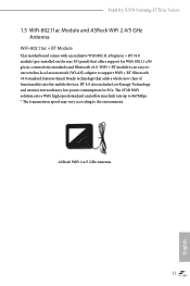
... Antenna 11 English Fatal1ty X370 Gaming-ITX/ac Series 1.5 WiFi-802.11ac Module and ASRock WiFi 2.4/5 GHz Antenna WiFi-802.11ac + BT Module This motherboard comes with an exclusive WiFi 802.11 a/b/g/n/ac + BT v4.0 module (pre-installed on the rear I/O panel) that adds a whole new class of functionality into the mobile devices. BT 4.0 also includes Low Energy...
... Antenna 11 English Fatal1ty X370 Gaming-ITX/ac Series 1.5 WiFi-802.11ac Module and ASRock WiFi 2.4/5 GHz Antenna WiFi-802.11ac + BT Module This motherboard comes with an exclusive WiFi 802.11 a/b/g/n/ac + BT v4.0 module (pre-installed on the rear I/O panel) that adds a whole new class of functionality into the mobile devices. BT 4.0 also includes Low Energy...

User Manual
Page 19
... on a grounded anti-static pad or in the bag that the motherboard fits into it. Chapter 2 Installation This is a Mini-ITX form factor motherboard. Doing so may cause physical injuries to you uninstall any motherboard settings. • Make sure to unplug the power cord before you handle the components. • Hold components by the...
... on a grounded anti-static pad or in the bag that the motherboard fits into it. Chapter 2 Installation This is a Mini-ITX form factor motherboard. Doing so may cause physical injuries to you uninstall any motherboard settings. • Make sure to unplug the power cord before you handle the components. • Hold components by the...

User Manual
Page 22
Please turn off the power or remove the power cord before changing a CPU or heatsink. You also need to spray thermal grease between the CPU and the heatsink to dissipate heat. Installing the CPU Box Cooler SR1 1 2 15 English Make sure that the CPU and the heatsink are securely fastened and in good contact with each other. Fatal1ty X370 Gaming-ITX/ac Series 2.2 Installing the CPU Fan and Heatsink After you install the CPU into this motherboard, it is necessary to install a larger heatsink and cooling fan to improve heat dissipation.
Please turn off the power or remove the power cord before changing a CPU or heatsink. You also need to spray thermal grease between the CPU and the heatsink to dissipate heat. Installing the CPU Box Cooler SR1 1 2 15 English Make sure that the CPU and the heatsink are securely fastened and in good contact with each other. Fatal1ty X370 Gaming-ITX/ac Series 2.2 Installing the CPU Fan and Heatsink After you install the CPU into this motherboard, it is necessary to install a larger heatsink and cooling fan to improve heat dissipation.

User Manual
Page 31
... SR DR DR Frequency (Mhz) 2400 2400 2400 2400 2400 2400 Ryzen CPUs: UDIMM Memory Slot A1 B1 - DR DR - 2.3 Installing Memory Modules (DIMM) This motherboard provides two 288-pin DDR4 (Double Data Rate 4) DIMM slots, and supports Dual Channel Memory Technology. 1. SR SR - - SR SR DR DR Frequency (Mhz) 2667...: Single rank DIMM, 1Rx4 or 1Rx8 on DIMM module label DR: Dual rank DIMM, 2Rx4 or 2Rx8 on DIMM module label 24 English otherwise, this motherboard and DIMM may be damaged.
... SR DR DR Frequency (Mhz) 2400 2400 2400 2400 2400 2400 Ryzen CPUs: UDIMM Memory Slot A1 B1 - DR DR - 2.3 Installing Memory Modules (DIMM) This motherboard provides two 288-pin DDR4 (Double Data Rate 4) DIMM slots, and supports Dual Channel Memory Technology. 1. SR SR - - SR SR DR DR Frequency (Mhz) 2667...: Single rank DIMM, 1Rx4 or 1Rx8 on DIMM module label DR: Dual rank DIMM, 2Rx4 or 2Rx8 on DIMM module label 24 English otherwise, this motherboard and DIMM may be damaged.

User Manual
Page 32
Fatal1ty X370 Gaming-ITX/ac Series The DIMM only fits in one correct orientation. It will cause permanent damage to the motherboard and the DIMM if you force the DIMM into the slot at incorrect orientation. 1 2 3 25 English
Fatal1ty X370 Gaming-ITX/ac Series The DIMM only fits in one correct orientation. It will cause permanent damage to the motherboard and the DIMM if you force the DIMM into the slot at incorrect orientation. 1 2 3 25 English

User Manual
Page 33
2.4 Expansion Slot (PCI Express Slot) There is installed. 26 English PCIe slot: PCIE1 (PCIe 3.0 x16 slot) is unplugged. Please read the documentation of the expansion card and make sure that the power supply is switched off or the power cord is used for the card before you start the installation. Before installing an expansion card, please make necessary hardware settings for PCI Express x16 lane width graphics cards.* * PCIE1 will downgrade to x8 mode when A-Series APU is 1 PCI Express slot on the motherboard.
2.4 Expansion Slot (PCI Express Slot) There is installed. 26 English PCIe slot: PCIE1 (PCIe 3.0 x16 slot) is unplugged. Please read the documentation of the expansion card and make sure that the power supply is switched off or the power cord is used for the card before you start the installation. Before installing an expansion card, please make necessary hardware settings for PCI Express x16 lane width graphics cards.* * PCIE1 will downgrade to x8 mode when A-Series APU is 1 PCI Express slot on the motherboard.

User Manual
Page 35
... caps over the headers and connectors will cause permanent damage to the pin assignments below. PWRBTN (Power Switch): Connect to this header according to the motherboard. You may differ by chassis. The LED keeps blinking when the system is in S3 sleep state. System Panel Header (9-pin PANEL1) (see p.6, No. 19...
... caps over the headers and connectors will cause permanent damage to the pin assignments below. PWRBTN (Power Switch): Connect to this header according to the motherboard. You may differ by chassis. The LED keeps blinking when the system is in S3 sleep state. System Panel Header (9-pin PANEL1) (see p.6, No. 19...

User Manual
Page 36
... can support two ports. This header is one header on this motherboard. Each USB 2.0 header can support two ports. Vbus IntA_PA_D+ IntA_PA_DGND IntA_PA_SSTX+ IntA_PA_SSTXGND IntA_PA_SSRX+ IntA_PA_SSRXVbus There is for connecting audio devices to 6.0 Gb/s data transfer rate. GND IntA_PB_SSRX+ IntA_PB_SSRX- Fatal1ty X370 Gaming-ITX/ac Series Serial ATA3 Connectors (SATA3_1: see p.6, No. 11) (SATA3_2: see p.6, No...
... can support two ports. This header is one header on this motherboard. Each USB 2.0 header can support two ports. Vbus IntA_PA_D+ IntA_PA_DGND IntA_PA_SSTX+ IntA_PA_SSTXGND IntA_PA_SSRX+ IntA_PA_SSRXVbus There is for connecting audio devices to 6.0 Gb/s data transfer rate. GND IntA_PB_SSRX+ IntA_PB_SSRX- Fatal1ty X370 Gaming-ITX/ac Series Serial ATA3 Connectors (SATA3_1: see p.6, No. 11) (SATA3_2: see p.6, No...

User Manual
Page 37
...Definition Audio supports Jack Sensing, but the panel wire on the chassis must support HDA to Pin 1-3. B. MIC_RET and OUT_RET are for the AC'97 audio panel. You don't need to MIC2_L. Chassis Optional/Water Pump Fan Connector (4-pin CHA_FAN/W_ PUMP) (see p.6, No. 4)... install your system. 2. English 30 CPU Fan Connector (4-pin CPU_FAN1) (see p.6, No. 17) GND FAN_VOLTAGE_CONTROL FAN_SPEED FAN_SPEED_CONTROL This motherboard provides two 4-Pin water cooling chassis fan connectors. Please follow the instructions in the Realtek Control panel and adjust "Recording Volume"....
...Definition Audio supports Jack Sensing, but the panel wire on the chassis must support HDA to Pin 1-3. B. MIC_RET and OUT_RET are for the AC'97 audio panel. You don't need to MIC2_L. Chassis Optional/Water Pump Fan Connector (4-pin CHA_FAN/W_ PUMP) (see p.6, No. 4)... install your system. 2. English 30 CPU Fan Connector (4-pin CPU_FAN1) (see p.6, No. 17) GND FAN_VOLTAGE_CONTROL FAN_SPEED FAN_SPEED_CONTROL This motherboard provides two 4-Pin water cooling chassis fan connectors. Please follow the instructions in the Realtek Control panel and adjust "Recording Volume"....

User Manual
Page 38
.... English 31 Caution: Never install the FAN LED cable in the wrong orientation; Fatal1ty X370 Gaming-ITX/ac Series ATX Power Connector (24-pin ATXPWR1) (see p.6, No. 7) ATX 12V Power Connector (8-pin ATX12V1) (see p.6, No. 1) AMD FAN LED Header (4-pin AMD_FAN_ LED1) (see p.6, No. 3) 12 24 1 13 5 1 8 4 1 12V G R B This motherboard provides a 24-pin ATX power connector.
.... English 31 Caution: Never install the FAN LED cable in the wrong orientation; Fatal1ty X370 Gaming-ITX/ac Series ATX Power Connector (24-pin ATXPWR1) (see p.6, No. 7) ATX 12V Power Connector (8-pin ATX12V1) (see p.6, No. 1) AMD FAN LED Header (4-pin AMD_FAN_ LED1) (see p.6, No. 3) 12 24 1 13 5 1 8 4 1 12V G R B This motherboard provides a 24-pin ATX power connector.

User Manual
Page 39
....com/kb/2720599/en-us 32 English Chapter 3 Software and Utilities Operation 3.1 Installing Drivers The Support CD that comes with the motherboard contains necessary drivers and useful utilities that the motherboard supports. The CD automatically displays the Main Menu if "AUTORUN" is enabled in the Support CD to install it. Running The.... Please click Install All or follow the installation wizard to display the menu. Utilities Menu The Utilities Menu shows the application software that enhance the motherboard's features.
....com/kb/2720599/en-us 32 English Chapter 3 Software and Utilities Operation 3.1 Installing Drivers The Support CD that comes with the motherboard contains necessary drivers and useful utilities that the motherboard supports. The CD automatically displays the Main Menu if "AUTORUN" is enabled in the Support CD to install it. Running The.... Please click Install All or follow the installation wizard to display the menu. Utilities Menu The Utilities Menu shows the application software that enhance the motherboard's features.

User Manual
Page 43
... utility. Hot News: The hot news section displays the various latest news. 3.3 ASRock Live Update & APP Shop The ASRock Live Update & APP Shop is an online store for purchasing and downloading software applications for your motherboard up to download apps from the ASRock Live Update & APP Shop. 3.3.1 UI Overview Category Panel Hot News Information...
... utility. Hot News: The hot news section displays the various latest news. 3.3 ASRock Live Update & APP Shop The ASRock Live Update & APP Shop is an online store for purchasing and downloading software applications for your motherboard up to download apps from the ASRock Live Update & APP Shop. 3.3.1 UI Overview Category Panel Hot News Information...
User Manual
Page 50
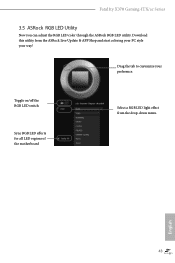
English 43 Toggle on/off the RGB LED switch Sync RGB LED effects for all LED regions of the motherboard Select a RGB LED light effect from the ASRock Live Update & APP Shop and start coloring your PC style your preference. Download this utility from the drop-down menu. Drag the tab to customize your way! Fatal1ty X370 Gaming-ITX/ac Series 3.5 ASRock RGB LED Utility Now you can adjust the RGB LED color through the ASRock RGB LED utility.
English 43 Toggle on/off the RGB LED switch Sync RGB LED effects for all LED regions of the motherboard Select a RGB LED light effect from the ASRock Live Update & APP Shop and start coloring your PC style your preference. Download this utility from the drop-down menu. Drag the tab to customize your way! Fatal1ty X370 Gaming-ITX/ac Series 3.5 ASRock RGB LED Utility Now you can adjust the RGB LED color through the ASRock RGB LED utility.

User Manual
Page 66
... for CPU Fan 1, or choose Customize to monitor the status of the hardware on your system, including the parameters of the CPU temperature, motherboard temperature, fan speed and voltage. Fatal1ty X370 Gaming-ITX/ac Series 4.6 Hardware Health Event Monitoring Screen This section allows you to set 5 CPU temperatures and assign a respective fan speed for each temperature...
... for CPU Fan 1, or choose Customize to monitor the status of the hardware on your system, including the parameters of the CPU temperature, motherboard temperature, fan speed and voltage. Fatal1ty X370 Gaming-ITX/ac Series 4.6 Hardware Health Event Monitoring Screen This section allows you to set 5 CPU temperatures and assign a respective fan speed for each temperature...

User Manual
Page 67
Chassis Fan 2 Setting Select a fan mode for Chassis Fan 2, or choose Customize to set 5 CPU temperatures and assign a respective fan speed for Chassis Fan 2. Over Temperature Protection When Over Temperature Protection is enabled, the system automatically shuts down when the motherboard is overheated. 60 English Chassis Fan 2 Temp Source Select a fan temperature source for each temperature. Chassis Fan 1 Temp Source Select a fan temperature source for each temperature. and assign a respective fan speed for Chassis Fan 1.
Chassis Fan 2 Setting Select a fan mode for Chassis Fan 2, or choose Customize to set 5 CPU temperatures and assign a respective fan speed for Chassis Fan 2. Over Temperature Protection When Over Temperature Protection is enabled, the system automatically shuts down when the motherboard is overheated. 60 English Chassis Fan 2 Temp Source Select a fan temperature source for each temperature. Chassis Fan 1 Temp Source Select a fan temperature source for each temperature. and assign a respective fan speed for Chassis Fan 1.

Quick Installation Guide
Page 1
...are used only for any interference received, including interference that may apply, see www.dtsc.ca.gov/hazardouswaste/ perchlorate" ASRock Website: http://www.asrock.com When you discard the Lithium battery in California, USA, please follow the related regulations in this documentation may or... consent of their respective companies, and are furnished for a particular purpose. CALIFORNIA, USA ONLY The Lithium battery adopted on this motherboard contains Perchlorate, a toxic substance controlled in this device must accept any errors or omissions that may not be constructed as a ...
...are used only for any interference received, including interference that may apply, see www.dtsc.ca.gov/hazardouswaste/ perchlorate" ASRock Website: http://www.asrock.com When you discard the Lithium battery in California, USA, please follow the related regulations in this documentation may or... consent of their respective companies, and are furnished for a particular purpose. CALIFORNIA, USA ONLY The Lithium battery adopted on this motherboard contains Perchlorate, a toxic substance controlled in this device must accept any errors or omissions that may not be constructed as a ...

