
User Manual
Page 6
...2 1.3 Motherboard Layout 7 1.4 I/O Panel 9 Chapter 2 Installation 11 2.1 Installing the CPU 12 2.2 Installing the CPU Fan and Heatsink 15 2.3 Installing Memory Modules (DIMM) 16 2.4 Expansion Slots (PCI Express Slots) 18 2.5 Jumpers Setup 19 2.6 Onboard Headers and Connectors 20 2.7 CrossFireXTM and Quad CrossFireXTM Operation Guide 25 2.7.1 Installing Two CrossFireXTM-Ready Graphics Cards 25 2.7.2 Driver Installation and Setup 27 2.8 M.2 WiFi/BT Module and Intel® CNVi (Integrated WiFi/BT) Installation Guide 28 2.9 M.2_SSD (NGFF) Module Installation Guide (M2_1...
...2 1.3 Motherboard Layout 7 1.4 I/O Panel 9 Chapter 2 Installation 11 2.1 Installing the CPU 12 2.2 Installing the CPU Fan and Heatsink 15 2.3 Installing Memory Modules (DIMM) 16 2.4 Expansion Slots (PCI Express Slots) 18 2.5 Jumpers Setup 19 2.6 Onboard Headers and Connectors 20 2.7 CrossFireXTM and Quad CrossFireXTM Operation Guide 25 2.7.1 Installing Two CrossFireXTM-Ready Graphics Cards 25 2.7.2 Driver Installation and Setup 27 2.8 M.2 WiFi/BT Module and Intel® CNVi (Integrated WiFi/BT) Installation Guide 28 2.9 M.2_SSD (NGFF) Module Installation Guide (M2_1...
User Manual
Page 9
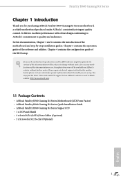
... the BIOS software might be updated, the content of the motherboard and step-by-step installation guides. Chapter 4 contains the configuration guide of the software and utilities. Fatal1ty B360 Gaming K4 Series Chapter 1 Introduction Thank you are using. Chapter 3 contains the operation guide of the BIOS setup. You may find the latest VGA cards and CPU support list on ASRock's website without notice. In this motherboard, please visit our website for specific information about the model you for M.2 Socket (Optional...
... the BIOS software might be updated, the content of the motherboard and step-by-step installation guides. Chapter 4 contains the configuration guide of the software and utilities. Fatal1ty B360 Gaming K4 Series Chapter 1 Introduction Thank you are using. Chapter 3 contains the operation guide of the BIOS setup. You may find the latest VGA cards and CPU support list on ASRock's website without notice. In this motherboard, please visit our website for specific information about the model you for M.2 Socket (Optional...
User Manual
Page 11
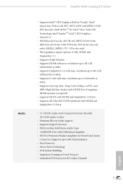
... Out port • Individual PCB Layers for R/L Audio Channel English 3 Fatal1ty B360 Gaming K4 Series Audio • Supports Intel® UHD Graphics Built-in Visuals : Intel® Quick Sync Video with AVC, MVC (S3D) and MPEG-2 Full HW Encode1, Intel® InTruTM 3D, Intel® Clear Video HD Technology, Intel® InsiderTM, Intel® UHD Graphics • DirectX 12 • HWAEncode/Decode: AVC/H.264, HEVC/H.265 8-bit...
... Out port • Individual PCB Layers for R/L Audio Channel English 3 Fatal1ty B360 Gaming K4 Series Audio • Supports Intel® UHD Graphics Built-in Visuals : Intel® Quick Sync Video with AVC, MVC (S3D) and MPEG-2 Full HW Encode1, Intel® InTruTM 3D, Intel® Clear Video HD Technology, Intel® InsiderTM, Intel® UHD Graphics • DirectX 12 • HWAEncode/Decode: AVC/H.264, HEVC/H.265 8-bit...
User Manual
Page 13
... SSD as boot disks ** Supports ASRock U.2 Kit Connector • 1 x COM Port Header • 1 x TPM Header • 1 x Chassis Intrusion header • 1 x Power LED and Speaker Header • 2 x RGB LED Headers * Support in total up to 12V/3A, 36W LED Strip • 1 x Addressable LED Header * Supports in total up to 5V/3A, 15W LED Strip • 1 x CPU Fan Connector (4-pin) * The CPU Fan Connector supports the CPU fan of maximum 1A (12W) fan power. • 1 x CPU/Water Pump Fan Connector (4-pin) (Smart Fan Speed Control) * The CPU/Water Pump Fan supports the water cooler fan of maximum...
... SSD as boot disks ** Supports ASRock U.2 Kit Connector • 1 x COM Port Header • 1 x TPM Header • 1 x Chassis Intrusion header • 1 x Power LED and Speaker Header • 2 x RGB LED Headers * Support in total up to 12V/3A, 36W LED Strip • 1 x Addressable LED Header * Supports in total up to 5V/3A, 15W LED Strip • 1 x CPU Fan Connector (4-pin) * The CPU Fan Connector supports the CPU fan of maximum 1A (12W) fan power. • 1 x CPU/Water Pump Fan Connector (4-pin) (Smart Fan Speed Control) * The CPU/Water Pump Fan supports the water cooler fan of maximum...
User Manual
Page 15
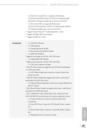
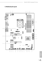
1.3 Motherboard Layout 1 2 RGB_LED2 1 ATX12V1 Fatal1ty B360 Gaming K4 Series 3 45 CPU_FAN1 USB 2.0 T: USB1 B: USB2 PS2 Keyboard /Mouse DISPLAY1 HDMI1 ATXPWR1 B360 Gaming K4 DDR4_A1 (64 bit, 288-pin module) DDR4_A2 (64 bit, 288-pin module) DDR4_B1 (64 bit, 288-pin module) DDR4_B2 (64 bit, 288-pin module) 6 USB 3.1 Gen1 T: USB1 B: USB2 USB 3.1 Gen2 T: USB31_TA_1 B: USB31_TC_1 Top: RJ-45 Top: USB3_3_4 Central/Bass LINE IN Center: REAR SPK Bottom: Optical SPDIF 26 CPU_FAN2/ WP 7 LAN Top...
1.3 Motherboard Layout 1 2 RGB_LED2 1 ATX12V1 Fatal1ty B360 Gaming K4 Series 3 45 CPU_FAN1 USB 2.0 T: USB1 B: USB2 PS2 Keyboard /Mouse DISPLAY1 HDMI1 ATXPWR1 B360 Gaming K4 DDR4_A1 (64 bit, 288-pin module) DDR4_A2 (64 bit, 288-pin module) DDR4_B1 (64 bit, 288-pin module) DDR4_B2 (64 bit, 288-pin module) 6 USB 3.1 Gen1 T: USB1 B: USB2 USB 3.1 Gen2 T: USB31_TA_1 B: USB31_TC_1 Top: RJ-45 Top: USB3_3_4 Central/Bass LINE IN Center: REAR SPK Bottom: Optical SPDIF 26 CPU_FAN2/ WP 7 LAN Top...
User Manual
Page 16
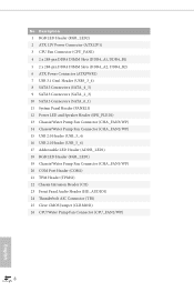
... Panel Header (PANEL1) 12 Power LED and Speaker Header (SPK_PLED1) 13 Chassis/Water Pump Fan Connector (CHA_FAN3/WP) 14 Chassis/Water Pump Fan Connector (CHA_FAN2/WP) 15 USB 2.0 Header (USB_3_4) 16 USB 2.0 Header (USB_5_6) 17 Addressable LED Header (ADDR_LED1) 18 RGB LED Header (RGB_LED1) 19 Chassis/Water Pump Fan Connector (CHA_FAN1/WP) 20 COM Port Header (COM1) 21 TPM Header (TPMS1) 22 Chassis Intrusion Header (CI1) 23 Front Panel Audio Header (HD_AUDIO1) 24 Thunderbolt AIC Connector (TB1) 25 Clear CMOS Jumper (CLRMOS1) 26 CPU/Water Pump Fan Connector...
... Panel Header (PANEL1) 12 Power LED and Speaker Header (SPK_PLED1) 13 Chassis/Water Pump Fan Connector (CHA_FAN3/WP) 14 Chassis/Water Pump Fan Connector (CHA_FAN2/WP) 15 USB 2.0 Header (USB_3_4) 16 USB 2.0 Header (USB_5_6) 17 Addressable LED Header (ADDR_LED1) 18 RGB LED Header (RGB_LED1) 19 Chassis/Water Pump Fan Connector (CHA_FAN1/WP) 20 COM Port Header (COM1) 21 TPM Header (TPMS1) 22 Chassis Intrusion Header (CI1) 23 Front Panel Audio Header (HD_AUDIO1) 24 Thunderbolt AIC Connector (TB1) 25 Clear CMOS Jumper (CLRMOS1) 26 CPU/Water Pump Fan Connector...

User Manual
Page 19
Fatal1ty B360 Gaming K4 Series Chapter 2 Installation This is an ATX form factor motherboard. Also remember to unplug the power cord before installing or removing the motherboard components. Before you install the motherboard, study the configuration of the following precautions before you install motherboard components or change any components, place them on a carpet. Doing so may cause physical injuries and damages to motherboard components. • In order to avoid damage...
Fatal1ty B360 Gaming K4 Series Chapter 2 Installation This is an ATX form factor motherboard. Also remember to unplug the power cord before installing or removing the motherboard components. Before you install the motherboard, study the configuration of the following precautions before you install motherboard components or change any components, place them on a carpet. Doing so may cause physical injuries and damages to motherboard components. • In order to avoid damage...
User Manual
Page 26
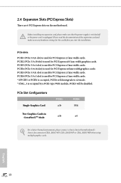
... cards. * If PCIE5 or PCIE6 is occupied, PCIE4 will downgrade to the motherboard's chassis fan connector (CHA_FAN1/WP, CHA_FAN2/WP or CHA_FAN3/WP) when using multiple graphics cards. 2.4 Expansion Slots (PCI Express Slots) There are 6 PCI Express slots on the motherboard. Please read the documentation of the expansion card and make sure that the power supply is switched off or the power cord is occupied by a PCIE-type WiFi module, PCIE3 will be disabled...
... cards. * If PCIE5 or PCIE6 is occupied, PCIE4 will downgrade to the motherboard's chassis fan connector (CHA_FAN1/WP, CHA_FAN2/WP or CHA_FAN3/WP) when using multiple graphics cards. 2.4 Expansion Slots (PCI Express Slots) There are 6 PCI Express slots on the motherboard. Please read the documentation of the expansion card and make sure that the power supply is switched off or the power cord is occupied by a PCIE-type WiFi module, PCIE3 will be disabled...
User Manual
Page 27
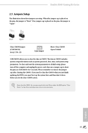
... default setup, please turn off the computer and unplug the power cord, then use a jumper cap to clear the data in CMOS includes system setup information such as system password, date, time, and system setup parameters. The data in CMOS. English 19 Fatal1ty B360 Gaming K4 Series 2.5 Jumpers Setup The illustration shows how jumpers are setup. When the jumper cap is placed on the pins, the jumper is "Short". Please adjust the BIOS option "Clear Status" to remove the jumper...
... default setup, please turn off the computer and unplug the power cord, then use a jumper cap to clear the data in CMOS includes system setup information such as system password, date, time, and system setup parameters. The data in CMOS. English 19 Fatal1ty B360 Gaming K4 Series 2.5 Jumpers Setup The illustration shows how jumpers are setup. When the jumper cap is placed on the pins, the jumper is "Short". Please adjust the BIOS option "Clear Status" to remove the jumper...
User Manual
Page 29
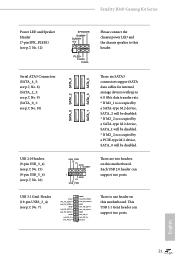
...+ GND IntA_PB_SSTXIntA_PB_SSTX+ GND IntA_PB_DIntA_PB_D+ Dummy 1 There is occupied by a SATA-type M.2 device, SATA_1 will be disabled. * If M2_2 is one header on this motherboard. Each USB 2.0 header can support two ports. Fatal1ty B360 Gaming K4 Series Power LED and Speaker Header (7-pin SPK_PLED1) (see p.7, No. 10) SATA_0 SATA_2 SATA_4 SATA_1 SATA_3 SATA_5 These six SATA3 connectors support SATA data cables for internal storage devices with up to this motherboard. Serial ATA3 Connectors (SATA_4_5: see p.7, No. 8) (SATA_2_3: see p.7, No. 9) (SATA_0_1: see...
...+ GND IntA_PB_SSTXIntA_PB_SSTX+ GND IntA_PB_DIntA_PB_D+ Dummy 1 There is occupied by a SATA-type M.2 device, SATA_1 will be disabled. * If M2_2 is one header on this motherboard. Each USB 2.0 header can support two ports. Fatal1ty B360 Gaming K4 Series Power LED and Speaker Header (7-pin SPK_PLED1) (see p.7, No. 10) SATA_0 SATA_2 SATA_4 SATA_1 SATA_3 SATA_5 These six SATA3 connectors support SATA data cables for internal storage devices with up to this motherboard. Serial ATA3 Connectors (SATA_4_5: see p.7, No. 8) (SATA_2_3: see p.7, No. 9) (SATA_0_1: see...
User Manual
Page 31
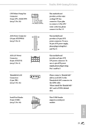
...pin ATX 12V power connector. To use a 20-pin ATX power supply, please plug it along Pin 1 and Pin 13. English 23 To use a 4-pin ATX power supply, please plug it along Pin 1 and Pin 5. This motherboard provides a 24-pin ATX power connector. Please connect a Thunderbolt™ add-in card (AIC) to the Thunderbolt AIC connector via the GPIO cable. *Please install the Thunderbolt™ AIC card to Pin 1-3. This COM1 header supports a serial port module. If you plan to connect a 3-Pin CPU water cooler fan, please connect it to PCIE4 (default slot). Fatal1ty B360 Gaming K4...
...pin ATX 12V power connector. To use a 20-pin ATX power supply, please plug it along Pin 1 and Pin 13. English 23 To use a 4-pin ATX power supply, please plug it along Pin 1 and Pin 5. This motherboard provides a 24-pin ATX power connector. Please connect a Thunderbolt™ add-in card (AIC) to the Thunderbolt AIC connector via the GPIO cable. *Please install the Thunderbolt™ AIC card to Pin 1-3. This COM1 header supports a serial port module. If you plan to connect a 3-Pin CPU water cooler fan, please connect it to PCIE4 (default slot). Fatal1ty B360 Gaming K4...
User Manual
Page 33
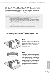
... installation guide. 2.7.1 Installing Two CrossFireXTM-Ready Graphics Cards Step 1 Insert one graphics card into PCIE2 slot and the other graphics card to the AMD's website for details.) English 25 CrossFire Bridge Step 2 Connect two graphics cards by installing a CrossFire Bridge on the CrossFire Bridge Interconnects on the slots. Please refer to two identical PCI Express x16 graphics cards. 1. Make sure that your graphics card driver supports AMD CrossFireXTM technology. Fatal1ty B360 Gaming K4 Series 2.7 CrossFireXTM and Quad CrossFireXTM Operation Guide This motherboard...
... installation guide. 2.7.1 Installing Two CrossFireXTM-Ready Graphics Cards Step 1 Insert one graphics card into PCIE2 slot and the other graphics card to the AMD's website for details.) English 25 CrossFire Bridge Step 2 Connect two graphics cards by installing a CrossFire Bridge on the CrossFire Bridge Interconnects on the slots. Please refer to two identical PCI Express x16 graphics cards. 1. Make sure that your graphics card driver supports AMD CrossFireXTM technology. Fatal1ty B360 Gaming K4 Series 2.7 CrossFireXTM and Quad CrossFireXTM Operation Guide This motherboard...
User Manual
Page 35
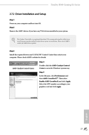
... using this utility to uninstall any VGA drivers installed in the Windows® system tray. Select the GPU number according to installation. AMD Catalyst Control Center Step 4 Double-click the AMD Catalyst Control Center icon in your graphics card and click Apply. Fatal1ty B360 Gaming K4 Series 2.7.2 Driver Installation and Setup Step 1 Power on your computer. Please check AMD's website for details. Step 3 Install the required drivers and CATALYST Control Center then restart your computer and boot...
... using this utility to uninstall any VGA drivers installed in the Windows® system tray. Select the GPU number according to installation. AMD Catalyst Control Center Step 4 Double-click the AMD Catalyst Control Center icon in your graphics card and click Apply. Fatal1ty B360 Gaming K4 Series 2.7.2 Driver Installation and Setup Step 1 Power on your computer. Please check AMD's website for details. Step 3 Install the required drivers and CATALYST Control Center then restart your computer and boot...
User Manual
Page 42
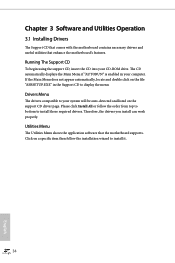
... will be auto-detected and listed on the support CD driver page. Utilities Menu The Utilities Menu shows the application software that enhance the motherboard's features. Chapter 3 Software and Utilities Operation 3.1 Installing Drivers The Support CD that comes with the motherboard contains necessary drivers and useful utilities that the motherboard supports. Drivers Menu The drivers compatible to install it. 34 English Please click Install All or follow the installation wizard to your CD-ROM drive. Therefore, the drivers you install can work properly.
... will be auto-detected and listed on the support CD driver page. Utilities Menu The Utilities Menu shows the application software that enhance the motherboard's features. Chapter 3 Software and Utilities Operation 3.1 Installing Drivers The Support CD that comes with the motherboard contains necessary drivers and useful utilities that the motherboard supports. Drivers Menu The drivers compatible to install it. 34 English Please click Install All or follow the installation wizard to your CD-ROM drive. Therefore, the drivers you install can work properly.
User Manual
Page 53
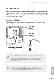
... installing or removing your RGB LED cable, please power off your RGB LED strips to do not come with a maximum power rating of 3A (12V) and length within 2 meters. 45 otherwise, the cable may cause damages to build their own stylish colorful lighting system. Fatal1ty B360 Gaming K4 Series 3.5 ASRock RGB LED ASRock RGB LED is a lighting control utility specifically designed for unique individuals with sophisticated tastes to motherboard components. 1. Connecting the LED Strip Connect your...
... installing or removing your RGB LED cable, please power off your RGB LED strips to do not come with a maximum power rating of 3A (12V) and length within 2 meters. 45 otherwise, the cable may cause damages to build their own stylish colorful lighting system. Fatal1ty B360 Gaming K4 Series 3.5 ASRock RGB LED ASRock RGB LED is a lighting control utility specifically designed for unique individuals with sophisticated tastes to motherboard components. 1. Connecting the LED Strip Connect your...
User Manual
Page 74
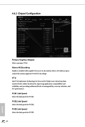
... 4.6.2 Chipset Configuration Primary Graphics Adapter Select a primary VGA. PCIE3 Link Speed Select the link speed for PCIE2. VT-d Intel® Virtualization Technology for PCIE1. PCIE1 Link Speed Select the link speed for Directed I/O helps your virtual machine monitor better utilize hardware by improving application compatibility and reliability, and providing additional levels of manageability, security, isolation, and I/O performance. Above 4G Decoding Enable or disable 64bit capable Devices to...
... 4.6.2 Chipset Configuration Primary Graphics Adapter Select a primary VGA. PCIE3 Link Speed Select the link speed for PCIE2. VT-d Intel® Virtualization Technology for PCIE1. PCIE1 Link Speed Select the link speed for Directed I/O helps your virtual machine monitor better utilize hardware by improving application compatibility and reliability, and providing additional levels of manageability, security, isolation, and I/O performance. Above 4G Decoding Enable or disable 64bit capable Devices to...
User Manual
Page 75
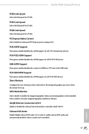
... Support This option enables/disables the control of ASPM on CPU side of memory that is allocated to enable onboard HD audio and automatically disable it when a sound card is installed. PCI Express Native Control Select Enable for all times. PCH PCIE ASPM Support This option enables/disables the ASPM support for enhanced PCI Express power saving in OS. Set to Auto to the integrated graphics processor when the system boots up. Fatal1ty B360 Gaming K4 Series PCIE4 Link Speed Select the link speed for PCIE4. IGPU Multi-Monitor Select disable...
... Support This option enables/disables the control of ASPM on CPU side of memory that is allocated to enable onboard HD audio and automatically disable it when a sound card is installed. PCI Express Native Control Select Enable for all times. PCH PCIE ASPM Support This option enables/disables the ASPM support for enhanced PCI Express power saving in OS. Set to Auto to the integrated graphics processor when the system boots up. Fatal1ty B360 Gaming K4 Series PCIE4 Link Speed Select the link speed for PCIE4. IGPU Multi-Monitor Select disable...
User Manual
Page 78
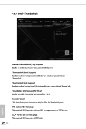
Thunderbolt Boot Support Enabled to allow booting from Usb devices which are present behind Thunderbolt. SW SMI on TBT Hot-plug When enbled, BIOS generates ACPI Notify. 70 English Thunderbolt Usb Support Enabled to allow booting from Bootable devices which are present behind Thunderbolt. Titan Ridge Workaround for OSUP Enable or disable Titan Ridge Workaround for the Thunderbolt ports. ACPI Notify on TBT hot-plug When enbled, BIOS generates software SMI to...
Thunderbolt Boot Support Enabled to allow booting from Usb devices which are present behind Thunderbolt. SW SMI on TBT Hot-plug When enbled, BIOS generates ACPI Notify. 70 English Thunderbolt Usb Support Enabled to allow booting from Bootable devices which are present behind Thunderbolt. Titan Ridge Workaround for OSUP Enable or disable Titan Ridge Workaround for the Thunderbolt ports. ACPI Notify on TBT hot-plug When enbled, BIOS generates software SMI to...
User Manual
Page 85
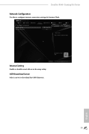
UEFI Download Server Select a server to configure internet connection settings for Internet Flash. Internet Setting Enable or disable sound effects in the setup utility. Fatal1ty B360 Gaming K4 Series Network Configuration Use this to download the UEFI firmware. 77 English
UEFI Download Server Select a server to configure internet connection settings for Internet Flash. Internet Setting Enable or disable sound effects in the setup utility. Fatal1ty B360 Gaming K4 Series Network Configuration Use this to download the UEFI firmware. 77 English
User Manual
Page 89
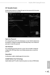
... Password Set or change the settings in the UEFI Setup Utility. Users are unable to change the password for the system. Fatal1ty B360 Gaming K4 Series 4.9 Security Screen In this option to use discrete TPM Module. 81 English Disable this section you may also clear the user password. Secure Boot Use this item to remove the password. You may set or change the supervisor/user password for the user account. Leave it blank and press enter to enable or disable support for the administrator account. User Password Set...
... Password Set or change the settings in the UEFI Setup Utility. Users are unable to change the password for the system. Fatal1ty B360 Gaming K4 Series 4.9 Security Screen In this option to use discrete TPM Module. 81 English Disable this section you may also clear the user password. Secure Boot Use this item to remove the password. You may set or change the supervisor/user password for the user account. Leave it blank and press enter to enable or disable support for the administrator account. User Password Set...


