
User Manual
Page 6
... 1.2 Specifications 2 1.3 Motherboard Layout 7 1.4 I/O Panel 9 Chapter 2 Installation 11 2.1 Installing the CPU 12 2.2 Installing the CPU Fan and Heatsink 15 2.3 Installing Memory Modules (DIMM) 16 2.4 Expansion Slots (PCI Express Slots) 18 2.5 Onboard Headers and Connectors 19 2.6 CrossFireXTM and Quad CrossFireXTM Operation Guide 24 2.6.1 Installing Two CrossFireXTM-Ready Graphics Cards 24 2.6.2 Driver Installation and Setup 26 2.7 M.2_SSD (NGFF) Module Installation Guide 27 Chapter 3 Software and Utilities Operation 30 3.1 Installing Drivers 30 3.2 ASRock Live...
... 1.2 Specifications 2 1.3 Motherboard Layout 7 1.4 I/O Panel 9 Chapter 2 Installation 11 2.1 Installing the CPU 12 2.2 Installing the CPU Fan and Heatsink 15 2.3 Installing Memory Modules (DIMM) 16 2.4 Expansion Slots (PCI Express Slots) 18 2.5 Onboard Headers and Connectors 19 2.6 CrossFireXTM and Quad CrossFireXTM Operation Guide 24 2.6.1 Installing Two CrossFireXTM-Ready Graphics Cards 24 2.6.2 Driver Installation and Setup 26 2.7 M.2_SSD (NGFF) Module Installation Guide 27 Chapter 3 Software and Utilities Operation 30 3.1 Installing Drivers 30 3.2 ASRock Live...
User Manual
Page 8
...; ASRock Fatal1ty B250M Performance Series Support CD • 2 x Serial ATA (SATA) Data Cables (Optional) • 2 x Screws for purchasing ASRock Fatal1ty B250M Performance Series motherboard, a reliable motherboard produced under ASRock's consistently stringent quality control. Chapter 3 contains the operation guide of the BIOS setup. Fatal1ty B250M Performance Series Chapter 1 Introduction Thank you are using. Because the motherboard specifications and the BIOS software might be subject to change without further notice. You may find the latest VGA cards and CPU support list on ASRock...
...; ASRock Fatal1ty B250M Performance Series Support CD • 2 x Serial ATA (SATA) Data Cables (Optional) • 2 x Screws for purchasing ASRock Fatal1ty B250M Performance Series motherboard, a reliable motherboard produced under ASRock's consistently stringent quality control. Chapter 3 contains the operation guide of the BIOS setup. Fatal1ty B250M Performance Series Chapter 1 Introduction Thank you are using. Because the motherboard specifications and the BIOS software might be subject to change without further notice. You may find the latest VGA cards and CPU support list on ASRock...
User Manual
Page 10
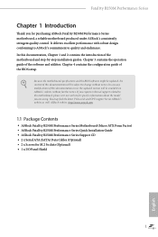
Fatal1ty B250M Performance Series Audio LAN • HWAEncode/Decode: VP8, HEVC 8b, VP9, HEVC 10b (For 7th Gen Intel® CPU) • HWA Encode/Decode: VP8 , HEVC 8b; resolution up to 1920x1200 @ 60Hz • Supports Auto Lip Sync, Deep Color (12bpc), xvYCC and HBR (High Bit Rate Audio) with HDMI Port (Compliant HDMI monitor is required to use an HD front panel audio module and enable the multi-channel audio feature through the...
Fatal1ty B250M Performance Series Audio LAN • HWAEncode/Decode: VP8, HEVC 8b, VP9, HEVC 10b (For 7th Gen Intel® CPU) • HWA Encode/Decode: VP8 , HEVC 8b; resolution up to 1920x1200 @ 60Hz • Supports Auto Lip Sync, Deep Color (12bpc), xvYCC and HBR (High Bit Rate Audio) with HDMI Port (Compliant HDMI monitor is required to use an HD front panel audio module and enable the multi-channel audio feature through the...

User Manual
Page 11
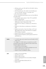
.../2280 M.2 PCI Express module up to Gen3 x4 (32 Gb/s)** ** If PCIE2 slot or PCIE3 slot is occupied, the PCIe-type M.2 device on M2_1 socket will run at Gen3 x2 (16 Gb/s). ** Supports Intel® OptaneTM Technology (M2_2 only) ** Supports NVMe SSD as boot disks ** Supports ASRock U.2 Kit English Connector • 1 x Print Port Header • 1 x COM Port Header • 1 x TPM Header • 1 x Chassis Intrusion and Speaker Header • 1 x AURA RGB LED Header • 2 x CPU Fan Connectors (1 x 4-pin, 1 x 3-pin) * The CPU Fan Connector supports the CPU fan of...
.../2280 M.2 PCI Express module up to Gen3 x4 (32 Gb/s)** ** If PCIE2 slot or PCIE3 slot is occupied, the PCIe-type M.2 device on M2_1 socket will run at Gen3 x2 (16 Gb/s). ** Supports Intel® OptaneTM Technology (M2_2 only) ** Supports NVMe SSD as boot disks ** Supports ASRock U.2 Kit English Connector • 1 x Print Port Header • 1 x COM Port Header • 1 x TPM Header • 1 x Chassis Intrusion and Speaker Header • 1 x AURA RGB LED Header • 2 x CPU Fan Connectors (1 x 4-pin, 1 x 3-pin) * The CPU Fan Connector supports the CPU fan of...
User Manual
Page 12
... pin ATX Power Connector • 1 x 8 pin 12V Power Connector • 1 x Front Panel Audio Connector • 2 x USB 2.0 Headers (Support 4 USB 2.0 ports) (Supports ESD Protection (ASRock Full Spike Protection)) • 1 x USB 3.0 Header (Supports 2 USB 3.0 ports) (Supports ESD Protection (ASRock Full Spike Protection)) BIOS Feature • AMI UEFI Legal BIOS with multilingual GUI support • ACPI 6.0 Compliant wake up events • SMBIOS 2.7 Support • CPU, GT_CPU, DRAM, PCH 1.0V, VCCIO, VCCSA, VCCST Voltage Multi-adjustment Hardware Monitor • CPU/Chassis temperature...
... pin ATX Power Connector • 1 x 8 pin 12V Power Connector • 1 x Front Panel Audio Connector • 2 x USB 2.0 Headers (Support 4 USB 2.0 ports) (Supports ESD Protection (ASRock Full Spike Protection)) • 1 x USB 3.0 Header (Supports 2 USB 3.0 ports) (Supports ESD Protection (ASRock Full Spike Protection)) BIOS Feature • AMI UEFI Legal BIOS with multilingual GUI support • ACPI 6.0 Compliant wake up events • SMBIOS 2.7 Support • CPU, GT_CPU, DRAM, PCH 1.0V, VCCIO, VCCSA, VCCST Voltage Multi-adjustment Hardware Monitor • CPU/Chassis temperature...

User Manual
Page 15
...) 2 Chassis Fan Connector (CHA_FAN1) 3 CPU Fan Connector (CPU_FAN1) 4 CPU Fan Connector (CPU_FAN2) 5 2 x 288-pin DDR4 DIMM Slots (DDR4_A1, DDR4_B1) 6 2 x 288-pin DDR4 DIMM Slots (DDR4_A2, DDR4_B2) 7 AURA RGB LED Header (RGB_HEADER1) 8 ATX Power Connector (ATXPWR1) 9 USB 3.0 Header (USB3_5_6) 10 SATA3 Connector (SATA3_0) 11 SATA3 Connector (SATA3_1) 12 Chassis Fan Connector (CHA_FAN2) 13 SATA3 Connector (SATA3_2) 14 SATA3 Connector (SATA3_3) 15 SATA3 Connector (SATA3_5) 16 SATA3 Connector (SATA3_4) 17 Clear CMOS Jumper (CLRMOS1) 18 Chassis Intrusion and Speaker Header (SPK_CI1) 19 System Panel...
...) 2 Chassis Fan Connector (CHA_FAN1) 3 CPU Fan Connector (CPU_FAN1) 4 CPU Fan Connector (CPU_FAN2) 5 2 x 288-pin DDR4 DIMM Slots (DDR4_A1, DDR4_B1) 6 2 x 288-pin DDR4 DIMM Slots (DDR4_A2, DDR4_B2) 7 AURA RGB LED Header (RGB_HEADER1) 8 ATX Power Connector (ATXPWR1) 9 USB 3.0 Header (USB3_5_6) 10 SATA3 Connector (SATA3_0) 11 SATA3 Connector (SATA3_1) 12 Chassis Fan Connector (CHA_FAN2) 13 SATA3 Connector (SATA3_2) 14 SATA3 Connector (SATA3_3) 15 SATA3 Connector (SATA3_5) 16 SATA3 Connector (SATA3_4) 17 Clear CMOS Jumper (CLRMOS1) 18 Chassis Intrusion and Speaker Header (SPK_CI1) 19 System Panel...

User Manual
Page 18
Fatal1ty B250M Performance Series Chapter 2 Installation This is a Micro ATX form factor motherboard. Also remember to unplug the power cord before you install the motherboard, study the configuration of the following precautions before installing or removing the motherboard components. Before you install motherboard components or change any components, place them on a carpet. Failure to the chassis, please do not touch the ICs. • Whenever you uninstall any motherboard settings. • Make sure...
Fatal1ty B250M Performance Series Chapter 2 Installation This is a Micro ATX form factor motherboard. Also remember to unplug the power cord before you install the motherboard, study the configuration of the following precautions before installing or removing the motherboard components. Before you install motherboard components or change any components, place them on a carpet. Failure to the chassis, please do not touch the ICs. • Whenever you uninstall any motherboard settings. • Make sure...

User Manual
Page 25
..., please connect a chassis fan to the motherboard's chassis fan connector (CHA_FAN1 or CHA_FAN2) when using multiple graphics cards. 2. Please read the documentation of the expansion card and make sure that the power supply is switched off or the power cord is used for PCI Express x1 lane width cards. PCIe slots: PCIE1 (PCIe 3.0 x16 slot) is occupied, the PCIe-type M.2 device on the motherboard. Before installing an expansion card, please make necessary hardware settings for PCI Express x1 lane width cards. PCIe Slot Configurations Single Graphics Card PCIE1...
..., please connect a chassis fan to the motherboard's chassis fan connector (CHA_FAN1 or CHA_FAN2) when using multiple graphics cards. 2. Please read the documentation of the expansion card and make sure that the power supply is switched off or the power cord is used for PCI Express x1 lane width cards. PCIe slots: PCIE1 (PCIe 3.0 x16 slot) is occupied, the PCIe-type M.2 device on the motherboard. Before installing an expansion card, please make necessary hardware settings for PCI Express x1 lane width cards. PCIe Slot Configurations Single Graphics Card PCIE1...

User Manual
Page 26
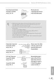
... power switch, reset switch and system status indicator on the chassis front panel. The front panel design may configure the way to the pin assignments below. The LED is on the chassis front panel. Do NOT place jumper caps over the headers and connectors will cause permanent damage to the reset switch on when the system is in S1/S3 sleep state. You may differ by chassis. RESET (Reset Switch): Connect to the motherboard. Fatal1ty B250M Performance Series 2.5 Onboard Headers...
... power switch, reset switch and system status indicator on the chassis front panel. The front panel design may configure the way to the pin assignments below. The LED is on the chassis front panel. Do NOT place jumper caps over the headers and connectors will cause permanent damage to the reset switch on when the system is in S1/S3 sleep state. You may differ by chassis. RESET (Reset Switch): Connect to the motherboard. Fatal1ty B250M Performance Series 2.5 Onboard Headers...
User Manual
Page 28
.... 2. FAN_VOLTAGE_CONTROL GND FAN_SPEED_CONTROL vides a 4-Pin CPU fan (Quiet Fan) connector. If you use an AC'97 audio panel, please install it to the front panel audio header by the steps below: A. Please follow the instructions in our manual and chassis manual to the "FrontMic" Tab in the Realtek Control panel and adjust "Recording Volume". C. You don't need to connect them for connecting audio devices to the ground pin. Fatal1ty B250M Performance Series Front Panel Audio Header (9-pin HD_AUDIO1) (see p.7, No. 25...
.... 2. FAN_VOLTAGE_CONTROL GND FAN_SPEED_CONTROL vides a 4-Pin CPU fan (Quiet Fan) connector. If you use an AC'97 audio panel, please install it to the front panel audio header by the steps below: A. Please follow the instructions in our manual and chassis manual to the "FrontMic" Tab in the Realtek Control panel and adjust "Recording Volume". C. You don't need to connect them for connecting audio devices to the ground pin. Fatal1ty B250M Performance Series Front Panel Audio Header (9-pin HD_AUDIO1) (see p.7, No. 25...

User Manual
Page 30
English 23 otherwise, the cable may be damaged. AURA RGB LED Header (4-pin RGB_HEADER1) (see p.7, No. 7) Fatal1ty B250M Performance Series AURA RGB LED header is used to connect RGB LED extension cable which allows users to choose from various LED lighting effects. Caution: Never install the RGB LED cable in the wrong orientation;
English 23 otherwise, the cable may be damaged. AURA RGB LED Header (4-pin RGB_HEADER1) (see p.7, No. 7) Fatal1ty B250M Performance Series AURA RGB LED header is used to connect RGB LED extension cable which allows users to choose from various LED lighting effects. Caution: Never install the RGB LED cable in the wrong orientation;

User Manual
Page 31
... CrossFireXTM mode. 5. Please refer to use identical CrossFireXTM-ready graphics cards that your graphics card driver supports AMD CrossFireXTM technology. CrossFire Bridge Step 2 Connect two graphics cards by installing a CrossFire Bridge on the CrossFire Bridge Interconnects on the slots. Different CrossFireXTM cards may require different methods to the AMD's website for detailed installation guide. 2.6.1 Installing Two CrossFireXTM-Ready Graphics Cards Step 1 Insert one graphics card into PCIE1 slot and the other graphics card to three identical PCI Express x16 graphics cards...
... CrossFireXTM mode. 5. Please refer to use identical CrossFireXTM-ready graphics cards that your graphics card driver supports AMD CrossFireXTM technology. CrossFire Bridge Step 2 Connect two graphics cards by installing a CrossFire Bridge on the CrossFire Bridge Interconnects on the slots. Different CrossFireXTM cards may require different methods to the AMD's website for detailed installation guide. 2.6.1 Installing Two CrossFireXTM-Ready Graphics Cards Step 1 Insert one graphics card into PCIE1 slot and the other graphics card to three identical PCI Express x16 graphics cards...
User Manual
Page 33
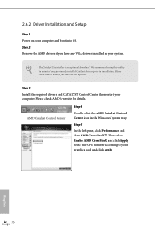
... AMD's website for AMD driver updates. Step 3 Install the required drivers and CATALYST Control Center then restart your computer and boot into OS. Then select Enable AMD CrossFireX and click Apply. Step 2 Remove the AMD drivers if you have any previously installed Catalyst drivers prior to your system. Please check AMD's website for details. We recommend using this utility to uninstall any VGA drivers installed in the Windows® system tray. 2.6.2 Driver Installation and Setup...
... AMD's website for AMD driver updates. Step 3 Install the required drivers and CATALYST Control Center then restart your computer and boot into OS. Then select Enable AMD CrossFireX and click Apply. Step 2 Remove the AMD drivers if you have any previously installed Catalyst drivers prior to your system. Please check AMD's website for details. We recommend using this utility to uninstall any VGA drivers installed in the Windows® system tray. 2.6.2 Driver Installation and Setup...
User Manual
Page 34
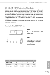
Fatal1ty B250M Performance Series 2.7 M.2_SSD (NGFF) Module Installation Guide The M.2, also known as the Next Generation Form Factor (NGFF), is a small size and versatile card edge connector that if M2_1 is occupied, the PCIe-type M.2 device on the PCB type and length of your M.2_SSD (NGFF) module, find the corresponding nut location to replace mPCIe and mSATA. English No. The Ultra M.2 Socket (M2_2) supports type 2230/2242/2260/2280...
Fatal1ty B250M Performance Series 2.7 M.2_SSD (NGFF) Module Installation Guide The M.2, also known as the Next Generation Form Factor (NGFF), is a small size and versatile card edge connector that if M2_1 is occupied, the PCIe-type M.2 device on the PCB type and length of your M.2_SSD (NGFF) module, find the corresponding nut location to replace mPCIe and mSATA. English No. The Ultra M.2 Socket (M2_2) supports type 2230/2242/2260/2280...
User Manual
Page 37
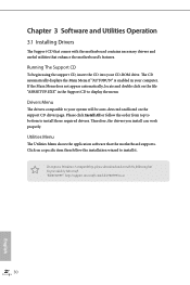
... your CD-ROM drive. Drivers Menu The drivers compatible to install those required drivers. Running The Support CD To begin using the support CD, insert the CD into your system will be auto-detected and listed on the support CD driver page. The CD automatically displays the Main Menu if "AUTORUN" is enabled in the Support CD to install it. Therefore, the drivers you install can work properly. Utilities Menu The Utilities Menu shows the application software that enhance...
... your CD-ROM drive. Drivers Menu The drivers compatible to install those required drivers. Running The Support CD To begin using the support CD, insert the CD into your system will be auto-detected and listed on the support CD driver page. The CD automatically displays the Main Menu if "AUTORUN" is enabled in the Support CD to install it. Therefore, the drivers you install can work properly. Utilities Menu The Utilities Menu shows the application software that enhance...

User Manual
Page 64
... used to route the interrupts it receives from peripheral buses to enable onboard HD audio and automatically disable it when a sound card is allocated to PIROI-PIROX. Enable/disable IOAPIC 24-119 Entries to expand to the integrated graphics processor when the system boots up. Share Memory Configure the size of the DMI Link. PCH PCIE ASPM Support This option enables/disables the ASPM support for all CPU downstream devices. Onboard LAN Enable or disable the onboard network interface controller. PCI Express...
... used to route the interrupts it receives from peripheral buses to enable onboard HD audio and automatically disable it when a sound card is allocated to PIROI-PIROX. Enable/disable IOAPIC 24-119 Entries to expand to the integrated graphics processor when the system boots up. Share Memory Configure the size of the DMI Link. PCH PCIE ASPM Support This option enables/disables the ASPM support for all CPU downstream devices. Onboard LAN Enable or disable the onboard network interface controller. PCI Express...
User Manual
Page 72
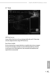
Please setup network configuration before using UEFI Tech Service. 4.7 Tools Fatal1ty B250M Performance Series UEFI Tech Service Contact ASRock Tech Service if you are having trouble with your system via an USB storage device, then downloads and installs the other required drivers automatically. 65 English Easy Driver Installer For users that don't have an optical disk drive to install the drivers from our support CD, Easy Driver Installer is a handy tool in the UEFI that installs the LAN driver to your PC.
Please setup network configuration before using UEFI Tech Service. 4.7 Tools Fatal1ty B250M Performance Series UEFI Tech Service Contact ASRock Tech Service if you are having trouble with your system via an USB storage device, then downloads and installs the other required drivers automatically. 65 English Easy Driver Installer For users that don't have an optical disk drive to install the drivers from our support CD, Easy Driver Installer is a handy tool in the UEFI that installs the LAN driver to your PC.

User Manual
Page 73
Boot Manager Timeout Enable/disable the Boot Manager Timeout. Instant Flash Save UEFI files in your USB storage device and run Instant Flash to plug in your UEFI. DHCP (Auto IP), Auto ASRock Internet Flash downloads and updates the latest UEFI firmware version from our servers for the Boot Manager. Please setup network configuration before using Internet Flash. *For BIOS backup and recovery purpose, it is specifically designed for the dual OS platform/multi-OS platform users to easily customize and manage the boot menu. *Please...
Boot Manager Timeout Enable/disable the Boot Manager Timeout. Instant Flash Save UEFI files in your USB storage device and run Instant Flash to plug in your UEFI. DHCP (Auto IP), Auto ASRock Internet Flash downloads and updates the latest UEFI firmware version from our servers for the Boot Manager. Please setup network configuration before using Internet Flash. *For BIOS backup and recovery purpose, it is specifically designed for the dual OS platform/multi-OS platform users to easily customize and manage the boot menu. *Please...

User Manual
Page 74
UEFI Download Server Select a server to configure internet connection settings for Internet Flash. Fatal1ty B250M Performance Series Network Configuration Use this to download the UEFI firmware. 67 English Internet Setting Enable or disable sound effects in the setup utility.
UEFI Download Server Select a server to configure internet connection settings for Internet Flash. Fatal1ty B250M Performance Series Network Configuration Use this to download the UEFI firmware. 67 English Internet Setting Enable or disable sound effects in the setup utility.

User Manual
Page 77
.... User Password Set or change the settings in the UEFI Setup Utility. Intel(R) Platform Trust Technology Enable/disable Intel PTT in the UEFI Setup Utility. Leave it blank and press enter to change the password for the administrator account. Only the administrator has authority to change the password for the user account. 4.9 Security Screen In this item to enable or disable support for Windows 8.1 Secure Boot. Disable this option to remove the password. Leave it blank and press enter to use discrete...
.... User Password Set or change the settings in the UEFI Setup Utility. Intel(R) Platform Trust Technology Enable/disable Intel PTT in the UEFI Setup Utility. Leave it blank and press enter to change the password for the administrator account. Only the administrator has authority to change the password for the user account. 4.9 Security Screen In this item to enable or disable support for Windows 8.1 Secure Boot. Disable this option to remove the password. Leave it blank and press enter to use discrete...


