
User Manual
Page 7
... - HD Audio Jack: Line in / Front Speaker / Microphone - 6 x SATA3 6.0 Gb/s connectors, support RAID (RAID 0, RAID 1, RAID 5 and RAID 10), NCQ, AHCI and "Hot Plug" functions - 1 x Print port header - 1 x COM port header - 1 x Chassis Intrusion header - 1 x CPU Fan connector (4-pin) - 1 x Chassis Fan connector (4-pin) - 1 x Power Fan connector (3-pin) - 1 x 24 pin ATX power connector...
... - HD Audio Jack: Line in / Front Speaker / Microphone - 6 x SATA3 6.0 Gb/s connectors, support RAID (RAID 0, RAID 1, RAID 5 and RAID 10), NCQ, AHCI and "Hot Plug" functions - 1 x Print port header - 1 x COM port header - 1 x Chassis Intrusion header - 1 x CPU Fan connector (4-pin) - 1 x Chassis Fan connector (4-pin) - 1 x Power Fan connector (3-pin) - 1 x 24 pin ATX power connector...

User Manual
Page 13
1.4 Motherboard Layout 29 28 FM2A85M-DG3 27 26 7 25 AMD A85X 8 (Hudson-D4) 9 Chipset 10 11 12 13 14 24 23 22 21 20 1918 17 16 15 1 ATX 12V Power ... SATA3 Connector (SATA_3) 15 SATA3 Connector (SATA_6) 16 SATA3 Connector (SATA_5) 17 SPI Flash Memory (64Mb) 18 USB 2.0 Header (USB4_5) 19 USB 2.0 Header (USB8_9) 20 Print Port Header (LPT1) 21 USB 3.0 Header (USB3_2_3) 22 COM Port Header (COM1) 23 Front Panel Audio Header (HD_AUDIO1) 24 PCI Slot (PCI1) 25 PCI Express...
1.4 Motherboard Layout 29 28 FM2A85M-DG3 27 26 7 25 AMD A85X 8 (Hudson-D4) 9 Chipset 10 11 12 13 14 24 23 22 21 20 1918 17 16 15 1 ATX 12V Power ... SATA3 Connector (SATA_3) 15 SATA3 Connector (SATA_6) 16 SATA3 Connector (SATA_5) 17 SPI Flash Memory (64Mb) 18 USB 2.0 Header (USB4_5) 19 USB 2.0 Header (USB8_9) 20 Print Port Header (LPT1) 21 USB 3.0 Header (USB3_2_3) 22 COM Port Header (COM1) 23 Front Panel Audio Header (HD_AUDIO1) 24 PCI Slot (PCI1) 25 PCI Express...

User Manual
Page 27
... power switch. The front panel design may configure the way to the hard drive activity LED on when the hard drive is an interface for print port cable that allows convenient connection of power switch, reset switch, power LED, hard drive activity LED, speaker and etc. PWRBTN (Power Switch): Connect ...indicator on the chassis front panel. PLED (System Power LED): Connect to perform a normal restart. HDLED (Hard Drive Activity LED): Connect to turn off (S5). Print Port Header (25-pin LPT1) (see p.13 No. 10) This header accommodates several system front panel functions.
... power switch. The front panel design may configure the way to the hard drive activity LED on when the hard drive is an interface for print port cable that allows convenient connection of power switch, reset switch, power LED, hard drive activity LED, speaker and etc. PWRBTN (Power Switch): Connect ...indicator on the chassis front panel. PLED (System Power LED): Connect to perform a normal restart. HDLED (Hard Drive Activity LED): Connect to turn off (S5). Print Port Header (25-pin LPT1) (see p.13 No. 10) This header accommodates several system front panel functions.

User Manual
Page 35
To change option for all the settings Save changes and exit the UEFI SETUP UTILITY Print screen Jump to the Exit Screen or exit the current screen 3.2 Main Screen When you to select the default page when entering UEFI setup utility. ...
To change option for all the settings Save changes and exit the UEFI SETUP UTILITY Print screen Jump to the Exit Screen or exit the current screen 3.2 Main Screen When you to select the default page when entering UEFI setup utility. ...
Quick Installation Guide
Page 2
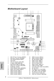
Motherboard Layout 29 28 FM2A85M-DG3 27 26 7 25 AMD A85X 8 (Hudson-D4) 9 Chipset 10 11 12 13 14 24 23 22 21 20 1918 17 16 15 1 ATX 12V Power ... Print Port Header (LPT1) 21 USB 3.0 Header (USB3_2_3) 22 COM Port Header (COM1) 23 Front Panel Audio Header (HD_AUDIO1) 24 PCI Slot (PCI1) 25 PCI Express 2.0 x1 Slot (PCIE2) 26 Clear CMOS Jumper (CLRCMOS1) 27 PCI Express 2.0 x16 Slot (PCIE1) 28 Chassis Intrusion Header (CI1) 29 Power Fan Connector (PWR_FAN1) 2 ASRock FM2A85M-DG3 Motherboard...
Motherboard Layout 29 28 FM2A85M-DG3 27 26 7 25 AMD A85X 8 (Hudson-D4) 9 Chipset 10 11 12 13 14 24 23 22 21 20 1918 17 16 15 1 ATX 12V Power ... Print Port Header (LPT1) 21 USB 3.0 Header (USB3_2_3) 22 COM Port Header (COM1) 23 Front Panel Audio Header (HD_AUDIO1) 24 PCI Slot (PCI1) 25 PCI Express 2.0 x1 Slot (PCIE2) 26 Clear CMOS Jumper (CLRCMOS1) 27 PCI Express 2.0 x16 Slot (PCIE1) 28 Chassis Intrusion Header (CI1) 29 Power Fan Connector (PWR_FAN1) 2 ASRock FM2A85M-DG3 Motherboard...

Quick Installation Guide
Page 6
...Speaker / Microphone - 6 x SATA3 6.0 Gb/s connectors, support RAID (RAID 0, RAID 1, RAID 5 and RAID 10), NCQ, AHCI and "Hot Plug" functions - 1 x Print port header - 1 x COM port header - 1 x Chassis Intrusion header - 1 x CPU Fan connector (4-pin) - 1 x Chassis Fan connector (4-pin) - 1 x... with LED (ACT/LINK LED and SPEED LED) - Voltage Monitoring: +12V, +5V, +3.3V, Vcore - Voltage Monitoring: +12V, +5V, +3.3V, Vcore ASRock FM2A85M-DG3 Motherboard English Rear Panel I/O Storage Connector BIOS Feature Support CD Hardware Monitor 6 I/O Panel - 1 x PS/2 Mouse Port - 1 x PS/2 Keyboard Port - ...
...Speaker / Microphone - 6 x SATA3 6.0 Gb/s connectors, support RAID (RAID 0, RAID 1, RAID 5 and RAID 10), NCQ, AHCI and "Hot Plug" functions - 1 x Print port header - 1 x COM port header - 1 x Chassis Intrusion header - 1 x CPU Fan connector (4-pin) - 1 x Chassis Fan connector (4-pin) - 1 x... with LED (ACT/LINK LED and SPEED LED) - Voltage Monitoring: +12V, +5V, +3.3V, Vcore - Voltage Monitoring: +12V, +5V, +3.3V, Vcore ASRock FM2A85M-DG3 Motherboard English Rear Panel I/O Storage Connector BIOS Feature Support CD Hardware Monitor 6 I/O Panel - 1 x PS/2 Mouse Port - 1 x PS/2 Keyboard Port - ...

Quick Installation Guide
Page 12
.... 9) 1 SPEAKER DUMMY +5V DUMMY Please connect the chassis speaker to this header according to the power status indicator on the chassis front panel. Print Port Header (25-pin LPT1) (see p.2 No. 10) This header accommodates several system front panel functions. System Panel Header (9-pin PANEL1) (... the chassis to the power switch on the chassis front panel. A front panel module mainly consists of printer devices. 12 ASRock FM2A85M-DG3 Motherboard English Connect the power switch, reset switch and system status indicator on when the system is reading or writing data. ...
.... 9) 1 SPEAKER DUMMY +5V DUMMY Please connect the chassis speaker to this header according to the power status indicator on the chassis front panel. Print Port Header (25-pin LPT1) (see p.2 No. 10) This header accommodates several system front panel functions. System Panel Header (9-pin PANEL1) (... the chassis to the power switch on the chassis front panel. A front panel module mainly consists of printer devices. 12 ASRock FM2A85M-DG3 Motherboard English Connect the power switch, reset switch and system status indicator on when the system is reading or writing data. ...

