
User Manual
Page 2
...the contents of this manual, ASRock does not provide warranty of any defect or error in the manual or product. "Perchlorate Material-special handling may cause undesired operation. CALIFORNIA, USA ONLY The Lithium battery adopted on this motherboard contains Perchlorate, a toxic substance... controlled in Perchlorate Best Management Practices (BMP) regulations passed by the purchaser for any errors or omissions that may apply, see www.dtsc.ca.gov/hazardouswaste/perchlorate" ASRock Website: http://www.asrock.com 2 When ...
...the contents of this manual, ASRock does not provide warranty of any defect or error in the manual or product. "Perchlorate Material-special handling may cause undesired operation. CALIFORNIA, USA ONLY The Lithium battery adopted on this motherboard contains Perchlorate, a toxic substance... controlled in Perchlorate Best Management Practices (BMP) regulations passed by the purchaser for any errors or omissions that may apply, see www.dtsc.ca.gov/hazardouswaste/perchlorate" ASRock Website: http://www.asrock.com 2 When ...

User Manual
Page 3
Contents 1 Introduction 5 1.1 Package Contents 5 1.2 Specifications 6 1.3 Motherboard Layout 11 1.4 I/O Panel 12 2 Installation 14 2.1 Screw Holes 14 2.2 Pre-installation Precautions 14 2.3 Installation of Memory Modules (DIMM 15 2.4 Expansion Slot (PCI Express Slot 16 2.5 ASRock Smart Remote Installation Guide 17 2.6 Jumpers Setup 19 2.7 Onboard Headers and Connectors 20 2.8 Serial ATA3 (SATA3) Hard Disks Installation...
Contents 1 Introduction 5 1.1 Package Contents 5 1.2 Specifications 6 1.3 Motherboard Layout 11 1.4 I/O Panel 12 2 Installation 14 2.1 Screw Holes 14 2.2 Pre-installation Precautions 14 2.3 Installation of Memory Modules (DIMM 15 2.4 Expansion Slot (PCI Express Slot 16 2.5 ASRock Smart Remote Installation Guide 17 2.6 Jumpers Setup 19 2.7 Onboard Headers and Connectors 20 2.8 Serial ATA3 (SATA3) Hard Disks Installation...

User Manual
Page 5
... "User Manual" in our support CD for specific information about the model you for purchasing ASRock E35LM1 motherboard, a reliable motherboard produced under ASRock's consistently stringent quality control. In this manual occur, the updated version will be available on ASRock website as well. In case any modifications of this manual, chapter 1 and 2 contain introduction...
... "User Manual" in our support CD for specific information about the model you for purchasing ASRock E35LM1 motherboard, a reliable motherboard produced under ASRock's consistently stringent quality control. In this manual occur, the updated version will be available on ASRock website as well. In case any modifications of this manual, chapter 1 and 2 contain introduction...

User Manual
Page 8
...;ned by overclocking. Simply install the APP Charger driver, it makes your iPhone charge much quickly from your system. ASRock website: http://www.asrock.com/Feature/AppCharger/index.asp 8 We are not responsible for possible damage caused by the chipset vendor and is a...drive, then you can update your Apple devices, such as iPhone/iPad/iPod Touch, ASRock has prepared a wonderful solution for system usage under Windows® 7 / VistaTM / XP. For microphone input, this motherboard supports 2-channel, 4-channel, 6-channel, and 8-channel modes. This convenient BIOS update...
...;ned by overclocking. Simply install the APP Charger driver, it makes your iPhone charge much quickly from your system. ASRock website: http://www.asrock.com/Feature/AppCharger/index.asp 8 We are not responsible for possible damage caused by the chipset vendor and is a...drive, then you can update your Apple devices, such as iPhone/iPad/iPod Touch, ASRock has prepared a wonderful solution for system usage under Windows® 7 / VistaTM / XP. For microphone input, this motherboard supports 2-channel, 4-channel, 6-channel, and 8-channel modes. This convenient BIOS update...

User Manual
Page 9
... OS 32-bit CPU. Please note that it also boosts the speed of the device. 8. ASRock Internet Flash searches for a more personal Internet experience. 6. ASRock motherboards are required. 12. ASRock XFast RAM shortens the loading time of Your Data: With the status window, you keep in ...touch with the ASRock SmartView utility that cannot be placed in order to update their lifespan. 10. In ...
... OS 32-bit CPU. Please note that it also boosts the speed of the device. 8. ASRock Internet Flash searches for a more personal Internet experience. 6. ASRock motherboards are required. 12. ASRock XFast RAM shortens the loading time of Your Data: With the status window, you keep in ...touch with the ASRock SmartView utility that cannot be placed in order to update their lifespan. 10. In ...

User Manual
Page 10
...thermal grease between the CPU and the heatsink when you to Intel's suggestion, the EuP ready power supply must meet EuP standards, an EuP ready motherboard and an EuP ready power supply are required. According to check with the power supply manufacturer for Energy Using Product, was a provision regulated by ...Microsoft® Windows® XP / XP 64-bit. 15. 13. Before you resume the system, please check if the CPU fan on the motherboard functions properly and unplug the power cord, then plug it back again. ASRock XFast RAM is detected, the system will automatically shutdown.
...thermal grease between the CPU and the heatsink when you to Intel's suggestion, the EuP ready power supply must meet EuP standards, an EuP ready motherboard and an EuP ready power supply are required. According to check with the power supply manufacturer for Energy Using Product, was a provision regulated by ...Microsoft® Windows® XP / XP 64-bit. 15. 13. Before you resume the system, please check if the CPU fan on the motherboard functions properly and unplug the power cord, then plug it back again. ASRock XFast RAM is detected, the system will automatically shutdown.

User Manual
Page 11
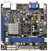
1.3 Motherboard Layout USB 2.0 T: USB0 B: USB1 12 34 17.0cm (6.7 in) E35LM1 CHA_FAN1 5 DDR3 CMOS Battery PS2 Keyboard/Mouse 6 CLRCMOS1 1 17.0cm (6.7 in) SATA3 6Gb/s DDR3_A1 (64 bit, 240-FpinSBmo8d0ul0e) DDR3_A2 (64 bit, 240-FpinSBmo8d0ul0e) CPU_FAN1 VGA1 ...
1.3 Motherboard Layout USB 2.0 T: USB0 B: USB1 12 34 17.0cm (6.7 in) E35LM1 CHA_FAN1 5 DDR3 CMOS Battery PS2 Keyboard/Mouse 6 CLRCMOS1 1 17.0cm (6.7 in) SATA3 6Gb/s DDR3_A1 (64 bit, 240-FpinSBmo8d0ul0e) DDR3_A2 (64 bit, 240-FpinSBmo8d0ul0e) CPU_FAN1 VGA1 ...

User Manual
Page 14
... that the power is switched off or the power cord is a Mini-ITX form factor (6.7" x 6.7", 17.0 x 17.0 cm) motherboard. Before you install the motherboard, study the configuration of the following precautions before you and damages to the chassis. Do not over-tighten the screws! Also... remember to ensure that comes with the component. To avoid damaging the motherboard components due to static electricity, NEVER place your chassis to use a grounded wrist strap or touch a safety grounded object before installing or...
... that the power is switched off or the power cord is a Mini-ITX form factor (6.7" x 6.7", 17.0 x 17.0 cm) motherboard. Before you install the motherboard, study the configuration of the following precautions before you and damages to the chassis. Do not over-tighten the screws! Also... remember to ensure that comes with the component. To avoid damaging the motherboard components due to static electricity, NEVER place your chassis to use a grounded wrist strap or touch a safety grounded object before installing or...

User Manual
Page 15
...incorrect orientation. Unlock a DIMM slot by pressing the retaining clips outward. It is properly seated. 15 It will cause permanent damage to the motherboard and the DIMM if you force the DIMM into the slot at both ends fully snap back in one correct orientation. 2.3 Installation of Memory... Modules (DIMM) E35LM1 motherboard provides two 240-pin DDR3 (Double Data Rate 3) DIMM slots. Step 2. Step 1. notch break notch break The DIMM only fits in ...
...incorrect orientation. Unlock a DIMM slot by pressing the retaining clips outward. It is properly seated. 15 It will cause permanent damage to the motherboard and the DIMM if you force the DIMM into the slot at both ends fully snap back in one correct orientation. 2.3 Installation of Memory... Modules (DIMM) E35LM1 motherboard provides two 240-pin DDR3 (Double Data Rate 3) DIMM slots. Step 2. Step 1. notch break notch break The DIMM only fits in ...

User Manual
Page 16
... used for the card before you intend to the chassis with the slot and press firmly until the card is completely seated on this motherboard. Installing an expansion card Step 1. Align the card connector with screws. PCIE slot: PCIE1 (PCIE x16 slot; Remove the bracket facing the slot that the... installing the expansion card, please make necessary hardware settings for PCI Express x4 lane width graphics cards. Step 2. Remove the system unit cover (if your motherboard is unplugged. Step 4. Step 5.
... used for the card before you intend to the chassis with the slot and press firmly until the card is completely seated on this motherboard. Installing an expansion card Step 1. Align the card connector with screws. PCIE slot: PCIE1 (PCIE x16 slot; Remove the bracket facing the slot that the... installing the expansion card, please make necessary hardware settings for PCI Express x4 lane width graphics cards. Step 2. Remove the system unit cover (if your motherboard is unplugged. Step 4. Step 5.

User Manual
Page 17
... Multi-Angle CIR Receiver to the USB 2.0 header (as below procedures for ASRock motherboard with CIR header. Step5. Execute ASRock support CD and install CIR Driver. (It is setting at the bottom of ASRock Smart Remote. Find the CIR header located next to enter BIOS Setup Utility... 2.0 header (9-pin, black) CIR header (4-pin, gray) Step2. Press or to the USB 2.0 header on ASRock motherboard. Enter Windows. 2.5 ASRock Smart Remote Installation Guide ASRock Smart Remote is only used for the quick installation and usage of driver list.) 17 Install Multi-Angle CIR Receiver ...
... Multi-Angle CIR Receiver to the USB 2.0 header (as below procedures for ASRock motherboard with CIR header. Step5. Execute ASRock support CD and install CIR Driver. (It is setting at the bottom of ASRock Smart Remote. Find the CIR header located next to enter BIOS Setup Utility... 2.0 header (9-pin, black) CIR header (4-pin, gray) Step2. Press or to the USB 2.0 header on ASRock motherboard. Enter Windows. 2.5 ASRock Smart Remote Installation Guide ASRock Smart Remote is only used for the quick installation and usage of driver list.) 17 Install Multi-Angle CIR Receiver ...

User Manual
Page 18
...(top, down and front), which is enabled, the other port will remain USB function. 2. Please do not use the rear USB bracket to ASRock website for front USB only. The Multi-Angle CIR Receiver does not support Hot-Plug function. Please refer to connect it before you boot the... system. * ASRock Smart Remote is used for the motherboard support list: http://www.asrock.com 18 Multi-Angle CIR Receiver is only supported by some of ASRock motherboards. Only one of the chassis on the rear panel. Please install it on ...
...(top, down and front), which is enabled, the other port will remain USB function. 2. Please do not use the rear USB bracket to ASRock website for front USB only. The Multi-Angle CIR Receiver does not support Hot-Plug function. Please refer to connect it before you boot the... system. * ASRock Smart Remote is used for the motherboard support list: http://www.asrock.com 18 Multi-Angle CIR Receiver is only supported by some of ASRock motherboards. Only one of the chassis on the rear panel. Please install it on ...

User Manual
Page 20
... header can be used to 6.0 Gb/s data transfer rate. SATA3_1 SATA3_2 SATA3_3 SATA3_4 Serial ATA (SATA) Data Cable (Optional) Either end of the motherboard! This header can be connected to the SATA / SATAII / SATA3 hard disk or the SATAII / SATA3 connector on this... 2.0 ports on the I/O panel, there are NOT jumpers. 2.7 Onboard Headers and Connectors Onboard headers and connectors are two USB 2.0 headers on this motherboard. Do NOT place jumper caps over the headers and connectors will cause permanent damage of the SATA data cable can support two USB 2.0 ports. Placing...
... header can be used to 6.0 Gb/s data transfer rate. SATA3_1 SATA3_2 SATA3_3 SATA3_4 Serial ATA (SATA) Data Cable (Optional) Either end of the motherboard! This header can be connected to the SATA / SATAII / SATA3 hard disk or the SATAII / SATA3 connector on this... 2.0 ports on the I/O panel, there are NOT jumpers. 2.7 Onboard Headers and Connectors Onboard headers and connectors are two USB 2.0 headers on this motherboard. Do NOT place jumper caps over the headers and connectors will cause permanent damage of the SATA data cable can support two USB 2.0 ports. Placing...

User Manual
Page 22
.... Serial port Header (9-pin COM1) (see p.11 No. 14) Please connect the fan cables to the fan connectors and match the black wire to this motherboard provides 24-pin ATX power connector, 12 24 it can still work if you adopt a traditional 20-pin ATX power supply. When connecting your power...
.... Serial port Header (9-pin COM1) (see p.11 No. 14) Please connect the fan cables to the fan connectors and match the black wire to this motherboard provides 24-pin ATX power connector, 12 24 it can still work if you adopt a traditional 20-pin ATX power supply. When connecting your power...

User Manual
Page 23
...bays of your chassis. STEP 3: Connect one end of the SATA data cable to the SATA3 hard disk. 2.9 Hot Plug Function for SATA3 HDDs This motherboard supports Hot Plug function for SATA3 in working condition. STEP 4: Connect the other end of the SATA data cable to the SATA3 hard disk. 2.8 Serial... ATA3 (SATA3) Hard Disks Installation This motherboard adopts AMD A50M chipset that it is called "Hot Plug" for the action to insert and remove the SATA3 HDDs while the system is Hot...
...bays of your chassis. STEP 3: Connect one end of the SATA data cable to the SATA3 hard disk. 2.9 Hot Plug Function for SATA3 HDDs This motherboard supports Hot Plug function for SATA3 in working condition. STEP 4: Connect the other end of the SATA data cable to the SATA3 hard disk. 2.8 Serial... ATA3 (SATA3) Hard Disks Installation This motherboard adopts AMD A50M chipset that it is called "Hot Plug" for the action to insert and remove the SATA3 HDDs while the system is Hot...

User Manual
Page 24
... (Red) B. Points of attention, before you process the SATA / SATAII / SATA3 HDD Hot Plug, please check below cable accessories from the motherboard gift box pack. The SATA / SATAII / SATA3 HDD, which cannot support Hot Plug function, will cause the HDD damage and data loss. Make..., the IDE 1x4-pin conventional power connector interface is available on our website: www.asrock.com 2. 2.10 SATA / SATAII / SATA3 HDD Hot Plug Feature and Operation Guide This motherboard supports Hot Plug feature for our motherboard, which supports SATA / SATAII / SATA3 HDD Hot Plug. * The SATA / ...
... (Red) B. Points of attention, before you process the SATA / SATAII / SATA3 HDD Hot Plug, please check below cable accessories from the motherboard gift box pack. The SATA / SATAII / SATA3 HDD, which cannot support Hot Plug function, will cause the HDD damage and data loss. Make..., the IDE 1x4-pin conventional power connector interface is available on our website: www.asrock.com 2. 2.10 SATA / SATAII / SATA3 HDD Hot Plug Feature and Operation Guide This motherboard supports Hot Plug feature for our motherboard, which supports SATA / SATAII / SATA3 HDD Hot Plug. * The SATA / ...

User Manual
Page 25
.... Step 1 Unplug SATA data cable from SATA / SATAII / SATA3 HDD side. 25 Step 1 Please connect SATA power cable 1x4-pin end Step 2 (White) to the motherboard's SATAII / SATA3 connector. SATA power cable 1x4-pin power connector (White) Step 3 Connect SATA 15-pin power cable connector (Black) end to the SATA / SATAII...
.... Step 1 Unplug SATA data cable from SATA / SATAII / SATA3 HDD side. 25 Step 1 Please connect SATA power cable 1x4-pin end Step 2 (White) to the motherboard's SATAII / SATA3 connector. SATA power cable 1x4-pin power connector (White) Step 3 Connect SATA 15-pin power cable connector (Black) end to the SATA / SATAII...

User Manual
Page 28
... mouse to enter the UEFI SETUP UTILITY after POST, restart the system by pressing + + , or by turning the system off and then back on the motherboard stores the UEFI SETUP UTILITY. The UEFI chip on .
... mouse to enter the UEFI SETUP UTILITY after POST, restart the system by pressing + + , or by turning the system off and then back on the motherboard stores the UEFI SETUP UTILITY. The UEFI chip on .

User Manual
Page 30
Bank Interleaving Interleaving allows memory accesses to enable or disable Power Saving Mode. The default value is selected, the motherboard will detect the memory module(s) inserted and assigns appropriate frequency automatically. DRAM Timing Configuration DRAM Frequency If [Auto] is [Disabled]. DRAM Timing Control Power Saving Mode Use this to be spread out over banks on the same node, or accross nodes, decreasing access contention. 30 3.3 OC Tweaker Screen In the OC Tweaker screen, you can set up overclocking features.
Bank Interleaving Interleaving allows memory accesses to enable or disable Power Saving Mode. The default value is selected, the motherboard will detect the memory module(s) inserted and assigns appropriate frequency automatically. DRAM Timing Configuration DRAM Frequency If [Auto] is [Disabled]. DRAM Timing Control Power Saving Mode Use this to be spread out over banks on the same node, or accross nodes, decreasing access contention. 30 3.3 OC Tweaker Screen In the OC Tweaker screen, you can set up overclocking features.

User Manual
Page 39
ACPI HPET Table Use this motherboard to enable or disable ACPI HPET Table. Please set this option to [Enabled] if you plan to use this item to submit Windows® VistaTM ...
ACPI HPET Table Use this motherboard to enable or disable ACPI HPET Table. Please set this option to [Enabled] if you plan to use this item to submit Windows® VistaTM ...

