
User Manual
Page 2
... purpose, without intent to the following two conditions: (1) this device may not cause harmful interference, and (2) this motherboard contains Perchlorate, a toxic substance controlled in this documentation. Version 1.0 Published April 2013 Copyright©2013 ASRock INC. Copyright Notice: No part of the FCC Rules. "Perchlorate Material-special handling may be registered trademarks or...
... purpose, without intent to the following two conditions: (1) this device may not cause harmful interference, and (2) this motherboard contains Perchlorate, a toxic substance controlled in this documentation. Version 1.0 Published April 2013 Copyright©2013 ASRock INC. Copyright Notice: No part of the FCC Rules. "Perchlorate Material-special handling may be registered trademarks or...

User Manual
Page 3
Contents Chapter 1 Introduction 1 1.1 Package Contents 1 1.2 Specifications 2 1.3 Unique Features 6 1.4 Motherboard Layout 10 1.5 I/O Panel 12 Chapter 2 Installation 14 2.1 Installing the CPU 15 2.2 Installing the CPU Fan and Heatsink 18 2.3 Installing Memory Modules (DIMM) 19 2.4 Expansion Slots (...
Contents Chapter 1 Introduction 1 1.1 Package Contents 1 1.2 Specifications 2 1.3 Unique Features 6 1.4 Motherboard Layout 10 1.5 I/O Panel 12 Chapter 2 Installation 14 2.1 Installing the CPU 15 2.2 Installing the CPU Fan and Heatsink 18 2.3 Installing Memory Modules (DIMM) 19 2.4 Expansion Slots (...

User Manual
Page 6
... 3 contains the operation guide of the BIOS setup. Chapter 4 contains the configuration guide of the software and utilities. ASRock website http://www.asrock.com. 1.1 Package Contents • ASRock B85 Pro4 Motherboard (ATX Form Factor) • ASRock B85 Pro4 Quick Installation Guide • ASRock B85 Pro4 Support CD • 2 x Serial ATA (SATA) Data Cables (Optional) • 1 x I/O Panel Shield 1 English You may find the...
... 3 contains the operation guide of the BIOS setup. Chapter 4 contains the configuration guide of the software and utilities. ASRock website http://www.asrock.com. 1.1 Package Contents • ASRock B85 Pro4 Motherboard (ATX Form Factor) • ASRock B85 Pro4 Quick Installation Guide • ASRock B85 Pro4 Support CD • 2 x Serial ATA (SATA) Data Cables (Optional) • 1 x I/O Panel Shield 1 English You may find the...

User Manual
Page 12
B85 Pro4 ASRock XFast RAM ASRock XFast RAM is a handy tool in the UEFI that installs the LAN driver to your SSDs or HDDs in order to extend their BIOS without fear of failing. Please note that don't have an optical disk drive to be used under Windows® 32-bit operating systems. ASRock... of internet access granted to dampness by enabling "Dehumidifier Function". You may prevent motherboard damages due to other required drivers automatically. 7 English ASRock Internet Flash ASRock Internet Flash downloads and updates the latest UEFI firmware version from our servers for ...
B85 Pro4 ASRock XFast RAM ASRock XFast RAM is a handy tool in the UEFI that installs the LAN driver to your SSDs or HDDs in order to extend their BIOS without fear of failing. Please note that don't have an optical disk drive to be used under Windows® 32-bit operating systems. ASRock... of internet access granted to dampness by enabling "Dehumidifier Function". You may prevent motherboard damages due to other required drivers automatically. 7 English ASRock Internet Flash ASRock Internet Flash downloads and updates the latest UEFI firmware version from our servers for ...

User Manual
Page 13
...this function, the PC will automatically switch off when the system is a blend of it hard to windows automatically! ASRock Home Cloud This motherboard supports remote wake with the onboard Intel LAN, so you can connect with another smartphone, tablet or computer. 8 English... ASRock Interactive UEFI ASRock Interactive UEFI is powered on the PC. ASRock Good Night LED ASRock Good Night LED technology offers you restart. Good Night LED...
...this function, the PC will automatically switch off when the system is a blend of it hard to windows automatically! ASRock Home Cloud This motherboard supports remote wake with the onboard Intel LAN, so you can connect with another smartphone, tablet or computer. 8 English... ASRock Interactive UEFI ASRock Interactive UEFI is powered on the PC. ASRock Good Night LED ASRock Good Night LED technology offers you restart. Good Night LED...

User Manual
Page 15
PS2 Mouse PS2 Keyboard 1.4 Motherboard Layout 1 PWR_FAN1 2 34 ATX12V1 DVI1 VGA DDR3_A1 (64 bit, 240-pin module) DDR3_A2 (64 bit, 240-pin module) DDR3_B1 (64 bit, 240-pin module) DDR3_B2... Express 3.0 25 X PCIE1 Fast LAN X X Fast USB Fast RAM LAN PCIE2 USB3_2_3 1 5 6 Front USB 3.0 CMOS Battery Audio CODEC PCIE3 RoHS Intel B85 PCIE4 64Mb BIOS SATA2_0 7 8 SATA2_1 HD_AUDIO1 1 SPDIF1_OUT1 1 COM1 1 B85 Pro4 PCI1 Super I/O SATA3_0 SATA3_3 PCI2 CLRCMOS1 1 SPEAKER1 1 IR1 1 USB4_5 1 SATA3_1 PLED1 1 SATA3_2 USB6_7 1 1 TPMS1 PLED PWRBTN CHA_FAN1 1 HDLED RESET PANEL1 9...
PS2 Mouse PS2 Keyboard 1.4 Motherboard Layout 1 PWR_FAN1 2 34 ATX12V1 DVI1 VGA DDR3_A1 (64 bit, 240-pin module) DDR3_A2 (64 bit, 240-pin module) DDR3_B1 (64 bit, 240-pin module) DDR3_B2... Express 3.0 25 X PCIE1 Fast LAN X X Fast USB Fast RAM LAN PCIE2 USB3_2_3 1 5 6 Front USB 3.0 CMOS Battery Audio CODEC PCIE3 RoHS Intel B85 PCIE4 64Mb BIOS SATA2_0 7 8 SATA2_1 HD_AUDIO1 1 SPDIF1_OUT1 1 COM1 1 B85 Pro4 PCI1 Super I/O SATA3_0 SATA3_3 PCI2 CLRCMOS1 1 SPEAKER1 1 IR1 1 USB4_5 1 SATA3_1 PLED1 1 SATA3_2 USB6_7 1 1 TPMS1 PLED PWRBTN CHA_FAN1 1 HDLED RESET PANEL1 9...

User Manual
Page 19
...before you handle the components. • Hold components by the edges and do not touch the ICs. • Whenever you install motherboard components or change any components, place them on a carpet. Failure to unplug the power cord before you uninstall any... of the following precautions before installing or removing the motherboard. Pre-installation Precautions Take note of your motherboard directly on a grounded anti-static pad or in the bag that the motherboard fits into it. Before you and damages to motherboard components. • In order to avoid damage from...
...before you handle the components. • Hold components by the edges and do not touch the ICs. • Whenever you install motherboard components or change any components, place them on a carpet. Failure to unplug the power cord before you uninstall any... of the following precautions before installing or removing the motherboard. Pre-installation Precautions Take note of your motherboard directly on a grounded anti-static pad or in the bag that the motherboard fits into it. Before you and damages to motherboard components. • In order to avoid damage from...

User Manual
Page 22
B85 Pro4 Please save and replace the cover if the processor is removed. The cover must be placed if you wish to return the motherboard for after service. 17 English
B85 Pro4 Please save and replace the cover if the processor is removed. The cover must be placed if you wish to return the motherboard for after service. 17 English

User Manual
Page 24
...is unable to activate Dual Channel Memory Technology with only one correct orientation. English 19 It will cause permanent damage to the motherboard and the DIMM if you always need to install a DDR or DDR2 memory module into the slot at incorrect orientation. ... Populated Populated DDR3_B1 Populated Populated DDR3_B2 Populated Populated The DIMM only fits in one or three memory module installed. 3. B85 Pro4 2.3 Installing Memory Modules (DIMM) This motherboard provides four 240-pin DDR3 (Double Data Rate 3) DIMM slots, and supports Dual Channel Memory Technology. 1.
...is unable to activate Dual Channel Memory Technology with only one correct orientation. English 19 It will cause permanent damage to the motherboard and the DIMM if you always need to install a DDR or DDR2 memory module into the slot at incorrect orientation. ... Populated Populated DDR3_B1 Populated Populated DDR3_B2 Populated Populated The DIMM only fits in one or three memory module installed. 3. B85 Pro4 2.3 Installing Memory Modules (DIMM) This motherboard provides four 240-pin DDR3 (Double Data Rate 3) DIMM slots, and supports Dual Channel Memory Technology. 1.

User Manual
Page 26
... is switched off or the power cord is unplugged. PCI slot: The PCI1 and PCI2 are 2 PCI slots and 4 PCI Express slots on the motherboard. PCIE4 (PCIe 2.0 x16 slot) is used for PCI Express x16 lane width graphics cards. PCIE3 (PCIe 2.0 x1 slot) is used for PCI .... PCIe slots: PCIE1 (PCIe 2.0 x1 slot) is used to the motherboard's chassis fan connector (CHA_FAN1 or CHA_FAN2) when using multiple graphics cards. PCIE2 (PCIe 3.0 x16 slot) is used for PCI Express x4 lane width graphics cards. B85 Pro4 2.4 Expansion Slots (PCI and PCI Express Slots) There are used for ...
... is switched off or the power cord is unplugged. PCI slot: The PCI1 and PCI2 are 2 PCI slots and 4 PCI Express slots on the motherboard. PCIE4 (PCIe 2.0 x16 slot) is used for PCI Express x16 lane width graphics cards. PCIE3 (PCIe 2.0 x1 slot) is used for PCI .... PCIe slots: PCIE1 (PCIe 2.0 x1 slot) is used to the motherboard's chassis fan connector (CHA_FAN1 or CHA_FAN2) when using multiple graphics cards. PCIE2 (PCIe 3.0 x16 slot) is used for PCI Express x4 lane width graphics cards. B85 Pro4 2.4 Expansion Slots (PCI and PCI Express Slots) There are used for ...

User Manual
Page 28
...The LED is on the chassis to turn off (S5). PLED (System Power LED): Connect to the reset switch on the chassis front panel. B85 Pro4 2.6 Onboard Headers and Connectors Onboard headers and connectors are matched correctly. Placing jumper caps over these headers and connectors. RESET (Reset Switch): Connect... front panel. The LED is off when the system is reading or writing data. HDLED (Hard Drive Activity LED): Connect to the motherboard. Press the reset switch to restart the computer if the computer freezes and fails to the power switch on the chassis front panel. ...
...The LED is on the chassis to turn off (S5). PLED (System Power LED): Connect to the reset switch on the chassis front panel. B85 Pro4 2.6 Onboard Headers and Connectors Onboard headers and connectors are matched correctly. Placing jumper caps over these headers and connectors. RESET (Reset Switch): Connect... front panel. The LED is off when the system is reading or writing data. HDLED (Hard Drive Activity LED): Connect to the motherboard. Press the reset switch to restart the computer if the computer freezes and fails to the power switch on the chassis front panel. ...

User Manual
Page 29
..., No. 17) USB_PWR PP+ GND DUMMY 1 GND P+ PUSB_PWR Besides two USB 2.0 ports on the I /O panel, there are two headers on this motherboard. USB 2.0 Headers (9-pin USB4_5) (see p.10, No. 18) (9-pin USB6_7) (see p.10, No. 10) SATA3_0 SATA3_3 SATA3_1 SATA3_2 These four ... Vbus IntA_PB_SSRXIntA_PB_SSRX+ GND IntA_PB_SSTXIntA_PB_SSTX+ GND IntA_PB_DIntA_PB_D+ Dummy 1 Besides four USB 3.0 ports on the I /O panel, there are one header on this motherboard. Each USB 2.0 header can support two ports. PLED+ PLED+ Please connect the chassis power LED to this header to 6.0 Gb/s data transfer ...
..., No. 17) USB_PWR PP+ GND DUMMY 1 GND P+ PUSB_PWR Besides two USB 2.0 ports on the I /O panel, there are two headers on this motherboard. USB 2.0 Headers (9-pin USB4_5) (see p.10, No. 18) (9-pin USB6_7) (see p.10, No. 10) SATA3_0 SATA3_3 SATA3_1 SATA3_2 These four ... Vbus IntA_PB_SSRXIntA_PB_SSRX+ GND IntA_PB_SSTXIntA_PB_SSTX+ GND IntA_PB_DIntA_PB_D+ Dummy 1 Besides four USB 3.0 ports on the I /O panel, there are one header on this motherboard. Each USB 2.0 header can support two ports. PLED+ PLED+ Please connect the chassis power LED to this header to 6.0 Gb/s data transfer ...

User Manual
Page 31
...pin ATX power connector. This COM1 header supports a serial port module. ATX Power Connector (24-pin ATXPWR1) (see p.10, No. 2) 8 5 This motherboard pro- To use a 4 1 4-pin ATX power supply, please plug it along Pin 1 and Pin 5. Infrared Module Header (5-pin IR1) (see p....10, No. 19) Serial Port Header (9-pin COM1) (see p.10, No. 27) GN D + 12V CPU_ FAN_SPEED FAN_SPEED_CONTROL GND + 12V CPU_ FAN_SPEED This motherboard provides a 4-Pin CPU fan (Quiet Fan) connector. CPU Fan Connectors 1 2 (4-pin CPU_FAN1) 3 (see p.10, No. 26) 4 (3-pin CPU_FAN2) (see p.10,...
...pin ATX power connector. This COM1 header supports a serial port module. ATX Power Connector (24-pin ATXPWR1) (see p.10, No. 2) 8 5 This motherboard pro- To use a 4 1 4-pin ATX power supply, please plug it along Pin 1 and Pin 5. Infrared Module Header (5-pin IR1) (see p....10, No. 19) Serial Port Header (9-pin COM1) (see p.10, No. 27) GN D + 12V CPU_ FAN_SPEED FAN_SPEED_CONTROL GND + 12V CPU_ FAN_SPEED This motherboard provides a 4-Pin CPU fan (Quiet Fan) connector. CPU Fan Connectors 1 2 (4-pin CPU_FAN1) 3 (see p.10, No. 26) 4 (3-pin CPU_FAN2) (see p.10,...
User Manual
Page 33
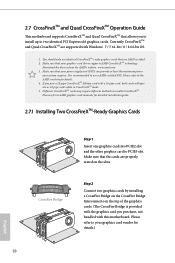
...-pipe card, both cards will operate as 12-pipe cards while in CrossFireXTM mode. 5. 2.7 CrossFireXTM and Quad CrossFireXTM Operation Guide This motherboard supports CrossFireXTM and Quad CrossFireXTM that allows you to install up to enable CrossFireXTM. You should only use a AMD certified PSU. If ...you pair a 12-pipe CrossFireXTM Edition card with this motherboard. Different CrossFireXTM cards may require different methods to two identical PCI Express x16 graphics cards. Currently CrossFireXTM and Quad CrossFireXTM are AMD ...
...-pipe card, both cards will operate as 12-pipe cards while in CrossFireXTM mode. 5. 2.7 CrossFireXTM and Quad CrossFireXTM Operation Guide This motherboard supports CrossFireXTM and Quad CrossFireXTM that allows you to install up to enable CrossFireXTM. You should only use a AMD certified PSU. If ...you pair a 12-pipe CrossFireXTM Edition card with this motherboard. Different CrossFireXTM cards may require different methods to two identical PCI Express x16 graphics cards. Currently CrossFireXTM and Quad CrossFireXTM are AMD ...

User Manual
Page 36
Utilities Menu The Utilities Menu shows the application software that enhance the motherboard's features. B85 Pro4 Chapter 3 Software and Utilities Operation 3.1 Installing Drivers The Support CD that comes with the motherboard contains necessary drivers and useful utilities that the motherboard supports. Drivers Menu The drivers compatible to display the menu. Click on the support CD driver...
Utilities Menu The Utilities Menu shows the application software that enhance the motherboard's features. B85 Pro4 Chapter 3 Software and Utilities Operation 3.1 Installing Drivers The Support CD that comes with the motherboard contains necessary drivers and useful utilities that the motherboard supports. Drivers Menu The drivers compatible to display the menu. Click on the support CD driver...

User Manual
Page 39
OC Tweaker Configurations for switching between the primary and secondary screen without replugging the connectors every time. Please set a hotkey for overclocking the system. HDMI-IN Connect two different devices to dampness. System Info View information about the system. 34 English Enable this function and configure the period of time until the computer powers on, and the duration of the dehumidifying process. Dehumidifier Prevent motherboard damages due to one monitor and toggle between the two devices.
OC Tweaker Configurations for switching between the primary and secondary screen without replugging the connectors every time. Please set a hotkey for overclocking the system. HDMI-IN Connect two different devices to dampness. System Info View information about the system. 34 English Enable this function and configure the period of time until the computer powers on, and the duration of the dehumidifying process. Dehumidifier Prevent motherboard damages due to one monitor and toggle between the two devices.

User Manual
Page 41
.... 2. Enter into HKEY_LOCAL_MACHINE\SYSTEM\CurrentControlSet\services\ msahci in Windows 8/7, type "Regedit" into 0. If Windows 8/7 is not in sleep mode. 3.3.1 System Requirements • Confirm whether your motherboard supports this feature. • Operating system: Microsoft Windows 8/7 (32- Click on the value Start and change the value from deep sleep, saving time and power...
.... 2. Enter into HKEY_LOCAL_MACHINE\SYSTEM\CurrentControlSet\services\ msahci in Windows 8/7, type "Regedit" into 0. If Windows 8/7 is not in sleep mode. 3.3.1 System Requirements • Confirm whether your motherboard supports this feature. • Operating system: Microsoft Windows 8/7 (32- Click on the value Start and change the value from deep sleep, saving time and power...

User Manual
Page 46
..., directly changing the SATA mode to AHCI may cause Windows 8/7 to refresh email or social networking applications. B85 Pro4 3.4 Intel® Smart Connect Technology Intel® Smart Connect Technology is a feature that periodically wakes your motherboard supports this feature. • Operating system: Microsoft Windows 8/7 (32- It saves your waiting time and keeps the...
..., directly changing the SATA mode to AHCI may cause Windows 8/7 to refresh email or social networking applications. B85 Pro4 3.4 Intel® Smart Connect Technology Intel® Smart Connect Technology is a feature that periodically wakes your motherboard supports this feature. • Operating system: Microsoft Windows 8/7 (32- It saves your waiting time and keeps the...

User Manual
Page 69
DRAM Frequency If [Auto] is selected, the motherboard will detect the memory module(s) inserted and assign the appropriate frequency automatically. DRAM Reference Clock Select Auto for optimized settings. Click OK to the memory ...
DRAM Frequency If [Auto] is selected, the motherboard will detect the memory module(s) inserted and assign the appropriate frequency automatically. DRAM Reference Clock Select Auto for optimized settings. Click OK to the memory ...

User Manual
Page 90
... a fan mode for Chassis Fan 1, or choose Customize to set 5 CPU temperatures and assign a respective fan speed for each temperature. B85 Pro4 4.6 Hardware Health Event Monitoring Screen This section allows you to set 5 CPU temperatures and assign a respective fan speed for each temperature. ... respective fan speed for each temperature. Over Temperature Protection When Over Temperature Protection is enabled, the system automatically shuts down when the motherboard is overheated. 85 English CPU Fan 1 & 2 Setting Select a fan mode for CPU Fans 1&2, or choose Customize to monitor...
... a fan mode for Chassis Fan 1, or choose Customize to set 5 CPU temperatures and assign a respective fan speed for each temperature. B85 Pro4 4.6 Hardware Health Event Monitoring Screen This section allows you to set 5 CPU temperatures and assign a respective fan speed for each temperature. ... respective fan speed for each temperature. Over Temperature Protection When Over Temperature Protection is enabled, the system automatically shuts down when the motherboard is overheated. 85 English CPU Fan 1 & 2 Setting Select a fan mode for CPU Fans 1&2, or choose Customize to monitor...

