
Intel Small Business Advantage Installation Guide
Page 3
When you want to install it manually, please locate and double-click the icon to execute the installer. 2. Click "Install" to continue. 3 However, if you install the all-in-one driver into your system from the ASRock support CD, Small Business Advantage will automatically be installed as well. 2. Click "Next" to continue with the installation. 3. Installing Small Business Advantage 1.
When you want to install it manually, please locate and double-click the icon to execute the installer. 2. Click "Install" to continue. 3 However, if you install the all-in-one driver into your system from the ASRock support CD, Small Business Advantage will automatically be installed as well. 2. Click "Next" to continue with the installation. 3. Installing Small Business Advantage 1.
Intel Small Business Advantage Installation Guide
Page 9
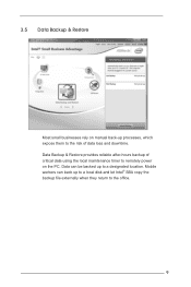
3.5 Data Backup & Restore Most small businesses rely on manual back-up processes, which expose them to the risk of critical data using the local maintenance timer to remotely power on the PC. Data can back up to the office. 9 Mobile workers can be backed up to a local disk and let Intel® SBA copy the backup file externally when they return to a designated location. Data Backup & Restore provides reliable after-hours backup of data loss and downtime.
3.5 Data Backup & Restore Most small businesses rely on manual back-up processes, which expose them to the risk of critical data using the local maintenance timer to remotely power on the PC. Data can back up to the office. 9 Mobile workers can be backed up to a local disk and let Intel® SBA copy the backup file externally when they return to a designated location. Data Backup & Restore provides reliable after-hours backup of data loss and downtime.

User Manual
Page 6
... documentation occur, the updated version will be available on ASRock's website as well. Chapter 3 contains the operation guide of the BIOS setup. In case any modifications of this manual, Chapter 1 and 2 contains the introduction of this motherboard, please visit our website for purchasing ASRock B85 Pro4 motherboard, a reliable motherboard produced under ASRock's consistently stringent quality control.
... documentation occur, the updated version will be available on ASRock's website as well. Chapter 3 contains the operation guide of the BIOS setup. In case any modifications of this manual, Chapter 1 and 2 contains the introduction of this motherboard, please visit our website for purchasing ASRock B85 Pro4 motherboard, a reliable motherboard produced under ASRock's consistently stringent quality control.

User Manual
Page 30
B85 Pro4 Front Panel Audio Header (9-pin HD_AUDIO1) (see p.10, No. 1) GND +12V FAN_SPEED FAN_SPEED_CONTROL Please connect fan cables to the fan connectors and match the black ... function correctly. Connect Audio_R (RIN) to OUT2_R and Audio_L (LIN) to MIC2_L. D. To activate the front mic, go to the "FrontMic" Tab in our manual and chassis manual to the front audio panel. 1. Chassis and Power Fan Connectors (4-pin CHA_FAN1) (see p.10, No. 12) (3-pin CHA_FAN2) (see p.10, No. 25) (3-pin PWR_FAN1...
B85 Pro4 Front Panel Audio Header (9-pin HD_AUDIO1) (see p.10, No. 1) GND +12V FAN_SPEED FAN_SPEED_CONTROL Please connect fan cables to the fan connectors and match the black ... function correctly. Connect Audio_R (RIN) to OUT2_R and Audio_L (LIN) to MIC2_L. D. To activate the front mic, go to the "FrontMic" Tab in our manual and chassis manual to the front audio panel. 1. Chassis and Power Fan Connectors (4-pin CHA_FAN1) (see p.10, No. 12) (3-pin CHA_FAN2) (see p.10, No. 25) (3-pin PWR_FAN1...
User Manual
Page 33
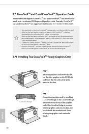
... one graphics card into PCIE2 slot and the other graphics card to two identical PCI Express x16 graphics cards. Please refer to AMD graphics card manuals for details. 4. If you to install up to PCIE3 slot. Please refer to use identical CrossFireXTM-ready graphics cards that your power supply unit (PSU...
... one graphics card into PCIE2 slot and the other graphics card to two identical PCI Express x16 graphics cards. Please refer to AMD graphics card manuals for details. 4. If you to install up to PCIE3 slot. Please refer to use identical CrossFireXTM-ready graphics cards that your power supply unit (PSU...

User Manual
Page 60
...your system. Click Compare Online to save your current settings. Click Apply to share with other overclockers. 55 English Manual Tuning Manual Tuning shows the major readings of profiles for the CPU core, GPU, and TurboBoost functions. Specify the duration ...and click Start Testing. Profiles Profiles shows a list of your overclocking settings and Benchmark results, which can share and compare the scores online with other users in the HWBot community. B85 Pro4...
...your system. Click Compare Online to save your current settings. Click Apply to share with other overclockers. 55 English Manual Tuning Manual Tuning shows the major readings of profiles for the CPU core, GPU, and TurboBoost functions. Specify the duration ...and click Start Testing. Profiles Profiles shows a list of your overclocking settings and Benchmark results, which can share and compare the scores online with other users in the HWBot community. B85 Pro4...

User Manual
Page 71
...is [Auto]. tWRRDDD Use this to write delay. 66 English tRDRD Configure between module read to read to change DRAM tRRSR Auto/Manual settings. The default is [Auto]. tRDRDDR Configure between module write to read delay from different ranks. tCKE Configure the period of ...write delay. tWRWRDD Configure between module write to write delay from different DIMMs. tRDWR Configure between module write to change DRAM tRWSR Auto/Manual settings. tWRRD Configure between module read delay. CAS Write Latency (tCWL) Configure CAS Write Latency. tREFI Configure refresh cycles at an...
...is [Auto]. tWRRDDD Use this to write delay. 66 English tRDRD Configure between module read to read to change DRAM tRRSR Auto/Manual settings. The default is [Auto]. tRDRDDR Configure between module write to read delay from different ranks. tCKE Configure the period of ...write delay. tWRWRDD Configure between module write to write delay from different DIMMs. tRDWR Configure between module write to change DRAM tRWSR Auto/Manual settings. tWRRD Configure between module read delay. CAS Write Latency (tCWL) Configure CAS Write Latency. tREFI Configure refresh cycles at an...

User Manual
Page 72
... B. ODT NOM (CHA) Use this to change ODT (CHA) Auto/Manual settings. ODT NOM (CHB) Use this to change ODT (CHB) Auto/Manual settings. IO-L (CHA) Configure IO latency for channel B. The default is [Auto]. IO-L (CHB) Configure IO latency for channel A. B85 Pro4 tRDWRDR Configure between module read to write delay from different...
... B. ODT NOM (CHA) Use this to change ODT (CHA) Auto/Manual settings. ODT NOM (CHB) Use this to change ODT (CHB) Auto/Manual settings. IO-L (CHA) Configure IO latency for channel B. The default is [Auto]. IO-L (CHB) Configure IO latency for channel A. B85 Pro4 tRDWRDR Configure between module read to write delay from different...

Quick Installation Guide
Page 27
...in the Realtek Control panel and adjust "Recording Volume". B. To activate the front mic, go to the "FrontMic" Tab in our manual and chassis manual to install your system. 2. Chassis Speaker Header (4-pin SPEAKER1) (see p.1, No. 23) 1 GND SPDIFOUT Please connect the SPDIF_OUT ...to MIC2_L. You don't need to function correctly. MIC_RET and OUT_RET are for connecting audio devices to this header with a cable. B85 Pro4 Front Panel Audio Header (9-pin HD_AUDIO1) (see p.1, No. 1) GND +12V FAN_SPEED FAN_SPEED_CONTROL Please connect fan cables to the fan connectors...
...in the Realtek Control panel and adjust "Recording Volume". B. To activate the front mic, go to the "FrontMic" Tab in our manual and chassis manual to install your system. 2. Chassis Speaker Header (4-pin SPEAKER1) (see p.1, No. 23) 1 GND SPDIFOUT Please connect the SPDIF_OUT ...to MIC2_L. You don't need to function correctly. MIC_RET and OUT_RET are for connecting audio devices to this header with a cable. B85 Pro4 Front Panel Audio Header (9-pin HD_AUDIO1) (see p.1, No. 1) GND +12V FAN_SPEED FAN_SPEED_CONTROL Please connect fan cables to the fan connectors...
