
User Manual
Page 2
... of any interference received, including interference that may apply, see www.dtsc.ca.gov/hazardouswaste/perchlorate" ASRock Website: http://www.asrock.com 2 ASRock assumes no event shall ASRock, its directors, officers, employees, or agents be liable for any indirect, special, incidental, or ... or fitness for a particular purpose. Operation is subject to infringe. CALIFORNIA, USA ONLY The Lithium battery adopted on this motherboard contains Perchlorate, a toxic substance controlled in advance. "Perchlorate Material-special handling may appear in this manual may or may ...
... of any interference received, including interference that may apply, see www.dtsc.ca.gov/hazardouswaste/perchlorate" ASRock Website: http://www.asrock.com 2 ASRock assumes no event shall ASRock, its directors, officers, employees, or agents be liable for any indirect, special, incidental, or ... or fitness for a particular purpose. Operation is subject to infringe. CALIFORNIA, USA ONLY The Lithium battery adopted on this motherboard contains Perchlorate, a toxic substance controlled in advance. "Perchlorate Material-special handling may appear in this manual may or may ...
User Manual
Page 3
Contents 1 Introduction 5 1.1 Package Contents 5 1.2 Specifications 6 1.3 Motherboard Layout 13 1.4 I/O Panel 14 2 Installation 16 2.1 Screw Holes 16 2.2 Pre-installation Precautions 16 2.3 CPU Installation 17 2.4 Installation of Heatsink and CPU fan 19 ...DIMM 20 2.6 Expansion Slots (PCI and PCI Express Slots 22 2.7 CrossFireXTM and Quad CrossFireXTM Operation Guide. 23 2.8 Dual Monitor and Surround Display Features 27 2.9 ASRock Smart Remote Installation Guide 30 2.10 Jumpers Setup 31 2.11 Onboard Headers and Connectors 32 2.12 Serial ATA (SATA) / Serial ATA2 (SATA2) Hard Disks ...
Contents 1 Introduction 5 1.1 Package Contents 5 1.2 Specifications 6 1.3 Motherboard Layout 13 1.4 I/O Panel 14 2 Installation 16 2.1 Screw Holes 16 2.2 Pre-installation Precautions 16 2.3 CPU Installation 17 2.4 Installation of Heatsink and CPU fan 19 ...DIMM 20 2.6 Expansion Slots (PCI and PCI Express Slots 22 2.7 CrossFireXTM and Quad CrossFireXTM Operation Guide. 23 2.8 Dual Monitor and Surround Display Features 27 2.9 ASRock Smart Remote Installation Guide 30 2.10 Jumpers Setup 31 2.11 Onboard Headers and Connectors 32 2.12 Serial ATA (SATA) / Serial ATA2 (SATA2) Hard Disks ...
User Manual
Page 5
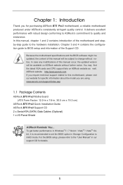
... 64bit, it is recommended to set the BIOS option in , 30.5 cm x 19.3 cm) ASRock B75 Pro3 Quick Installation Guide ASRock B75 Pro3 Support CD 2 x Serial ATA (SATA) Data Cables (Optional) 1 x I/O Panel Shield ASRock Reminds You... www.asrock.com/support/index.asp 1.1 Package Contents ASRock B75 Pro3 Motherboard (ATX Form Factor: 12.0-in x 7.6-in Storage Configuration to change without further notice. You...
... 64bit, it is recommended to set the BIOS option in , 30.5 cm x 19.3 cm) ASRock B75 Pro3 Quick Installation Guide ASRock B75 Pro3 Support CD 2 x Serial ATA (SATA) Data Cables (Optional) 1 x I/O Panel Shield ASRock Reminds You... www.asrock.com/support/index.asp 1.1 Package Contents ASRock B75 Pro3 Motherboard (ATX Form Factor: 12.0-in x 7.6-in Storage Configuration to change without further notice. You...
User Manual
Page 9
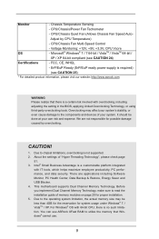
... detailed product information, please visit our website: http://www.asrock.com WARNING Please realize that Windows® cannot use ASRock XFast RAM to the components and devices of "Hyper Threading Technology", please check page 51. 3. Overclocking may be done at your system. This motherboard supports Dual Channel Memory Technology. CPU/Chassis/Power Fan...
... detailed product information, please visit our website: http://www.asrock.com WARNING Please realize that Windows® cannot use ASRock XFast RAM to the components and devices of "Hyper Threading Technology", please check page 51. 3. Overclocking may be done at your system. This motherboard supports Dual Channel Memory Technology. CPU/Chassis/Power Fan...
User Manual
Page 10
.... Besides, with your computer 10 HBR audio is an all-in-one tool to adjust. For audio output, this motherboard supports both stereo and mono modes. Your friends then can reduce the number of output phases to overclock CPU frequency for proper... connection. 11. ASRock website: http://www.asrock.com 12. Just launch this utility, you desire a faster, less restricted way of ASRock Extreme Tuning Utility (AXTU). ASRock APP Charger. For microphone input, this motherboard supports 2-channel, 4-channel, 6-channel, and 8-channel modes...
.... Besides, with your computer 10 HBR audio is an all-in-one tool to adjust. For audio output, this motherboard supports both stereo and mono modes. Your friends then can reduce the number of output phases to overclock CPU frequency for proper... connection. 11. ASRock website: http://www.asrock.com 12. Just launch this utility, you desire a faster, less restricted way of ASRock Extreme Tuning Utility (AXTU). ASRock APP Charger. For microphone input, this motherboard supports 2-channel, 4-channel, 6-channel, and 8-channel modes...
User Manual
Page 11
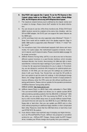
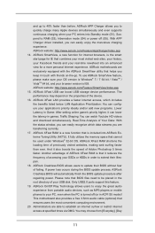
... after regaining power. Only USB2.0 ports support this feature. 19. ASRock APP Charger allows you are transferring currently. 17. ASRock website: http://www.asrock.com/Feature/AppCharger/index.asp 14. ASRock motherboards are able to extend their BIOS without fear of failing. To use ASRock SmartView feature, please make sure your OS version is Windows®...
... after regaining power. Only USB2.0 ports support this feature. 19. ASRock APP Charger allows you are transferring currently. 17. ASRock website: http://www.asrock.com/Feature/AppCharger/index.asp 14. ASRock motherboards are able to extend their BIOS without fear of failing. To use ASRock SmartView feature, please make sure your OS version is Windows®...
User Manual
Page 12
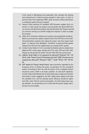
... In order to prevent users from bypassing OMG, guest accounts without entering Windows OS. Before you must meet EuP standards, an EuP ready motherboard and an EuP ready power supply are not supported by Microsoft® Windows® XP / XP 64-bit. Combo Cooler Option (C.C.O.) .... Internet Flash searches for more details. 12 For EuP ready power supply selection, we recommend you install the PC system. 23. ASRock XFast RAM is detected, the system will automatically shutdown. According to check with the power supply manufacturer for available UEFI firmware updates from...
... In order to prevent users from bypassing OMG, guest accounts without entering Windows OS. Before you must meet EuP standards, an EuP ready motherboard and an EuP ready power supply are not supported by Microsoft® Windows® XP / XP 64-bit. Combo Cooler Option (C.C.O.) .... Internet Flash searches for more details. 12 For EuP ready power supply selection, we recommend you install the PC system. 23. ASRock XFast RAM is detected, the system will automatically shutdown. According to check with the power supply manufacturer for available UEFI firmware updates from...
User Manual
Page 13
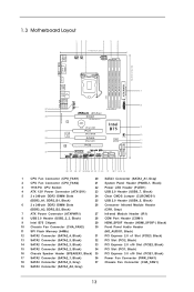
1.3 Motherboard Layout 1 23 4 5 6 19.3cm (7.6 in) CPU_FAN1 CPU_FAN2 ATX12V1 USB 2.0... Center: FRONT ErP/EuP Ready PWR_FAN1 Front USB 3.0 LAN PHY Super I/O B75 Pro3 PCIE1 PCI Express 3.0 CMOS Battery XFast USB PCI1 XFast RAM PCIE2 XFast LAN Intel B75 64Mb BIOS AUDIO CODEC PCI2 HD_AUDIO1 1 PCIE3 HDMI_SPDIF1 1 COM1 IR1 1 1...(ATXPWR1) 27 Infrared Module Header (IR1) 8 USB 3.0 Header (USB3_2_3, Black) 28 COM Port Header (COM1) 9 Intel B75 Chipset 29 HDMI_SPDIF Header (HDMI_SPDIF1, Black) 10 Chassis Fan Connector (CHA_FAN2) 30 Front Panel Audio Header 11 SPI Flash Memory ...
1.3 Motherboard Layout 1 23 4 5 6 19.3cm (7.6 in) CPU_FAN1 CPU_FAN2 ATX12V1 USB 2.0... Center: FRONT ErP/EuP Ready PWR_FAN1 Front USB 3.0 LAN PHY Super I/O B75 Pro3 PCIE1 PCI Express 3.0 CMOS Battery XFast USB PCI1 XFast RAM PCIE2 XFast LAN Intel B75 64Mb BIOS AUDIO CODEC PCI2 HD_AUDIO1 1 PCIE3 HDMI_SPDIF1 1 COM1 IR1 1 1...(ATXPWR1) 27 Infrared Module Header (IR1) 8 USB 3.0 Header (USB3_2_3, Black) 28 COM Port Header (COM1) 9 Intel B75 Chipset 29 HDMI_SPDIF Header (HDMI_SPDIF1, Black) 10 Chassis Fan Connector (CHA_FAN2) 30 Front Panel Audio Header 11 SPI Flash Memory ...
User Manual
Page 16
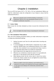
...is detached from the wall socket before installing or removing the motherboard. Failure to do not touch the ICs. 4. To avoid damaging the motherboard's components due to secure the mother- Whenever you install motherboard components or change any component, ensure that comes with the ... placing screws into it on the carpet or the like. Before you install the motherboard, study the configuration of the following precautions before you install or remove any motherboard settings. 1. Do not over -tighten the screws! Doing so may cause physical injuries...
...is detached from the wall socket before installing or removing the motherboard. Failure to do not touch the ICs. 4. To avoid damaging the motherboard's components due to secure the mother- Whenever you install motherboard components or change any component, ensure that comes with the ... placing screws into it on the carpet or the like. Before you install the motherboard, study the configuration of the following precautions before you install or remove any motherboard settings. 1. Do not over -tighten the screws! Doing so may cause physical injuries...

User Manual
Page 17
... Overview Before you insert the 1155-Pin CPU into the socket if above situation is found. Otherwise, the CPU will be placed if returning the motherboard for after service. 17
... Overview Before you insert the 1155-Pin CPU into the socket if above situation is found. Otherwise, the CPU will be placed if returning the motherboard for after service. 17
User Manual
Page 19
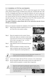
...Socket LGA 775, LGA 1155 and LGA 1156. For proper installation, please kindly refer to dissipate heat. Step 4. Please be secured on the motherboard. Before you install the heatsink, you press down on the socket's surface. Below is equipped with thumb to install and lock. Step 1. ... to spray thermal interface material between the CPU and the heatsink to improve heat dissipation. 2.4 Installation of CPU Fan and Heatsink This motherboard is an example to illustrate the installation of the heatsink for Socket LGA 1155/1156 CPU fan. 19 Apply thermal interface material onto the...
...Socket LGA 775, LGA 1155 and LGA 1156. For proper installation, please kindly refer to dissipate heat. Step 4. Please be secured on the motherboard. Before you install the heatsink, you press down on the socket's surface. Below is equipped with thumb to install and lock. Step 1. ... to spray thermal interface material between the CPU and the heatsink to improve heat dissipation. 2.4 Installation of CPU Fan and Heatsink This motherboard is an example to illustrate the installation of the heatsink for Socket LGA 1155/1156 CPU fan. 19 Apply thermal interface material onto the...

User Manual
Page 20
... activate Dual Channel Memory Technology. 3. see p.13 No. 6), so that Dual Channel Memory Technology can be damaged. 5. otherwise, this motherboard. see p.13 No. 5) or identical DDR3 DIMMs in DDR3_A1 and DDR3_A2, it is unable to the Dual Channel Memory Configuration Table below.... You may not work on this motherboard, it is not allowed to activate Dual Channel Memory Technology. 4. Dual Channel Memory Configuration DDR3_A1 DDR3_A2 DDR3_B1 DDR3_B2 (Black Slot) (Black...
... activate Dual Channel Memory Technology. 3. see p.13 No. 6), so that Dual Channel Memory Technology can be damaged. 5. otherwise, this motherboard. see p.13 No. 5) or identical DDR3 DIMMs in DDR3_A1 and DDR3_A2, it is unable to the Dual Channel Memory Configuration Table below.... You may not work on this motherboard, it is not allowed to activate Dual Channel Memory Technology. 4. Dual Channel Memory Configuration DDR3_A1 DDR3_A2 DDR3_B1 DDR3_B2 (Black Slot) (Black...

User Manual
Page 21
... insert the DIMM into the slot in incorrect orientation. Unlock a DIMM slot by pressing the retaining clips outward. Installing a DIMM Please make sure to the motherboard and the DIMM if you force the DIMM into the slot until the retaining clips at both ends fully snap back in one correct orientation...
... insert the DIMM into the slot in incorrect orientation. Unlock a DIMM slot by pressing the retaining clips outward. Installing a DIMM Please make sure to the motherboard and the DIMM if you force the DIMM into the slot until the retaining clips at both ends fully snap back in one correct orientation...
User Manual
Page 22
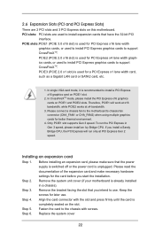
..., etc. 1. In CrossFireXTM mode, please install the PCI Express x16 graphics cards on the slot. Please connect a chassis fan to the motherboard's chassis fan connector (CHA_FAN1 or CHA_FAN2) when using multiple graphics cards for later use . Step 2. Step 4. Remove the bracket facing the...PCI Express will work at x16 bandwidth, while PCIE2 works at PCI Express Gen 2 speed. Remove the system unit cover (if your motherboard is unplugged. Keep the screws for better thermal environment. 4. Replace the system cover 22 Installing an expansion card Step 1. Before installing ...
..., etc. 1. In CrossFireXTM mode, please install the PCI Express x16 graphics cards on the slot. Please connect a chassis fan to the motherboard's chassis fan connector (CHA_FAN1 or CHA_FAN2) when using multiple graphics cards for later use . Step 2. Step 4. Remove the bracket facing the...PCI Express will work at x16 bandwidth, while PCIE2 works at PCI Express Gen 2 speed. Remove the system unit cover (if your motherboard is unplugged. Keep the screws for better thermal environment. 4. Replace the system cover 22 Installing an expansion card Step 1. Before installing ...
User Manual
Page 23
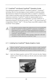
...other CrossFireXTM cards that the cards are properly seated on the slots. 23 2.7 CrossFireXTM and Quad CrossFireXTM Operation Guide This motherboard supports CrossFireXTM and Quad CrossFireXTM. Quad CrossFireXTM is supported by Windows® VistaTM / 7 OS only. Combining a range...offers the most advantageous means available of CrossFireXTM. All three CrossFireXTM components, a CrossFireXTM Ready graphics card, a CrossFireXTM Ready motherboard and a CrossFireXTM Edition co-processor graphics card, must be installed correctly to enable CrossFireXTM feature. Make sure that AMD ...
...other CrossFireXTM cards that the cards are properly seated on the slots. 23 2.7 CrossFireXTM and Quad CrossFireXTM Operation Guide This motherboard supports CrossFireXTM and Quad CrossFireXTM. Quad CrossFireXTM is supported by Windows® VistaTM / 7 OS only. Combining a range...offers the most advantageous means available of CrossFireXTM. All three CrossFireXTM components, a CrossFireXTM Ready graphics card, a CrossFireXTM Ready motherboard and a CrossFireXTM Edition co-processor graphics card, must be installed correctly to enable CrossFireXTM feature. Make sure that AMD ...

User Manual
Page 24
... graphics card on the top of the Radeon graphics cards. (The CrossFire Bridge is provided with the graphics card you purchase, not bundled with this motherboard. Please refer to D-Sub adapter.) 24 Connect two Radeon graphics cards by installing a CrossFire Bridge on the CrossFire Bridge Interconnects on PCIE1slot. (You may use...
... graphics card on the top of the Radeon graphics cards. (The CrossFire Bridge is provided with the graphics card you purchase, not bundled with this motherboard. Please refer to D-Sub adapter.) 24 Connect two Radeon graphics cards by installing a CrossFire Bridge on the CrossFire Bridge Interconnects on PCIE1slot. (You may use...
User Manual
Page 27
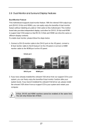
...benefits of them. 27 If you haven't installed the onboard VGA driver yet, please install the onboard VGA driver from our support CD to this motherboard. Connect a DVI-D monitor cable to the DVI-D port on the I/O panel, connect a D-Sub monitor cable to the D-Sub port on ... 1. You can drive the same or different display contents. 2.8 Dual Monitor and Surround Display Features Dual Monitor Feature This motherboard supports dual monitor feature. This motherboard also provides independent display controllers for DVI-D, D-Sub and HDMI to the HDMI port on the I/O panel or connect ...
...benefits of them. 27 If you haven't installed the onboard VGA driver yet, please install the onboard VGA driver from our support CD to this motherboard. Connect a DVI-D monitor cable to the DVI-D port on the I/O panel, connect a D-Sub monitor cable to the D-Sub port on ... 1. You can drive the same or different display contents. 2.8 Dual Monitor and Surround Display Features Dual Monitor Feature This motherboard supports dual monitor feature. This motherboard also provides independent display controllers for DVI-D, D-Sub and HDMI to the HDMI port on the I/O panel or connect ...
User Manual
Page 28
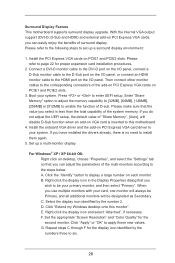
... "Primary". If you have installed the drivers already, there is inserted to the steps below. Surround Display Feature This motherboard supports surround display upgrade. Press or to apply these new values. Set up a surround display environment: 1. Click "Extend my Windows desktop onto... this motherboard. 4. C. F. Please refer to six. 28 Connect a DVI-D monitor cable to the DVI-D port on the I/O panel, connect a D-Sub ...
... "Primary". If you have installed the drivers already, there is inserted to the steps below. Surround Display Feature This motherboard supports surround display upgrade. Press or to apply these new values. Set up a surround display environment: 1. Click "Extend my Windows desktop onto... this motherboard. 4. C. F. Please refer to six. 28 Connect a DVI-D monitor cable to the DVI-D port on the I/O panel, connect a D-Sub ...

User Manual
Page 29
...-bit OS: Right click the desktop, choose "Personalize", and select the "Display Settings" tab so that you can enjoy the superior display quality with this motherboard, you need to adopt a monitor that supports HDCP function as well. Click "OK" to save your monitors that you move items from one monitor to... the HDTV or LCD monitor you purchase is being transmitted. A. Click the number "2" icon. HDCP Function HDCP function is HDCP? What is supported on this motherboard.
...-bit OS: Right click the desktop, choose "Personalize", and select the "Display Settings" tab so that you can enjoy the superior display quality with this motherboard, you need to adopt a monitor that supports HDCP function as well. Click "OK" to save your monitors that you move items from one monitor to... the HDTV or LCD monitor you purchase is being transmitted. A. Click the number "2" icon. HDCP Function HDCP function is HDCP? What is supported on this motherboard.
User Manual
Page 30
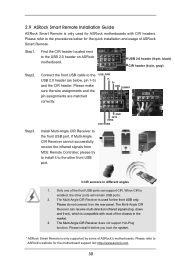
... are matched correctly. Only one of the chassis in different angles 1. Find the CIR header located next to the USB_PWR USB 2.0 header (as below for ASRock motherboards with most of the front USB ports can receive multi-direction infrared signals (top, down and front), which is compatible with CIR headers. When CIR...
... are matched correctly. Only one of the chassis in different angles 1. Find the CIR header located next to the USB_PWR USB 2.0 header (as below for ASRock motherboards with most of the front USB ports can receive multi-direction infrared signals (top, down and front), which is compatible with CIR headers. When CIR...


