
RAID Installation Guide
Page 2
... in parallel, interleaved stacks. AMD BIOS RAID Installation Guide AMD BIOS RAID Installation Guide is a method combining two or more hard disk drives into one drive to the entire system since it contains a complete copy of Independent Disks", which is an instruction for you to configure RAID functions by following the detailed instruction of the "User Manual" in our support CD, then you make a SATA driver diskette, press or to enter BIOS setup to set . WARNING!! It provides...
... in parallel, interleaved stacks. AMD BIOS RAID Installation Guide AMD BIOS RAID Installation Guide is a method combining two or more hard disk drives into one drive to the entire system since it contains a complete copy of Independent Disks", which is an instruction for you to configure RAID functions by following the detailed instruction of the "User Manual" in our support CD, then you make a SATA driver diskette, press or to enter BIOS setup to set . WARNING!! It provides...

RAID Installation Guide
Page 8
... of the USB port. B. Go to enter UEFI setup utility. During Windows installation process, when Disk selection page show up, please click . Plug a USB drive into the DVD-ROM drive. Please download the "SATA Floppy Imaged driver" from ASRock's website A. E. B. During system boot, press or key to Tools Easy RAID Installer F. STEP 4: Windows installation A. STEP 3.1: Copy RAID driver to a USB flash drive You can choose either STEP 3.1 or STEP 3.2 to find the driver inside your USB flash disk. D. Please install the DVD-ROM. Click to finish the configuration...
... of the USB port. B. Go to enter UEFI setup utility. During Windows installation process, when Disk selection page show up, please click . Plug a USB drive into the DVD-ROM drive. Please download the "SATA Floppy Imaged driver" from ASRock's website A. E. B. During system boot, press or key to Tools Easy RAID Installer F. STEP 4: Windows installation A. STEP 3.1: Copy RAID driver to a USB flash drive You can choose either STEP 3.1 or STEP 3.2 to find the driver inside your USB flash disk. D. Please install the DVD-ROM. Click to finish the configuration...

RAID Installation Guide
Page 14
... RAID Installer F. B. Plug a USB drive into the DVD-ROM drive. Go to exit. STEP 2.1: Copy RAID driver to a USB flash drive You can choose either STEP2.1 or STEP2.2 to enter UEFI setup utility. Please install the DVD-ROM. During system boot, press or key to finish the configuration. D. Follow instructions to finish the driver copy process. A. STEP 2.2: Download driver from ASRock's website and unzip the file into your USB flash disk. 14 K. C. Insert the Support CD into one of the USB port. E. Please download the "SATA Floppy Imaged driver...
... RAID Installer F. B. Plug a USB drive into the DVD-ROM drive. Go to exit. STEP 2.1: Copy RAID driver to a USB flash drive You can choose either STEP2.1 or STEP2.2 to enter UEFI setup utility. Please install the DVD-ROM. During system boot, press or key to finish the configuration. D. Follow instructions to finish the driver copy process. A. STEP 2.2: Download driver from ASRock's website and unzip the file into your USB flash disk. 14 K. C. Insert the Support CD into one of the USB port. E. Please download the "SATA Floppy Imaged driver...

RAID Installation Guide
Page 15
... . Click to boot from AMD website. Three drivers must be loaded. While this system is booting, please press F11 to open the F11 boot menu again. It might look different when using a different version driver package. 15 A. If the system restarts at this point, then please open the boot menu that is the first. It should list the USB drive as a UEFI device. Using SATA/NVMe RAID driver package (version 9.2.0.127) from...
... . Click to boot from AMD website. Three drivers must be loaded. While this system is booting, please press F11 to open the F11 boot menu again. It might look different when using a different version driver package. 15 A. If the system restarts at this point, then please open the boot menu that is the first. It should list the USB drive as a UEFI device. Using SATA/NVMe RAID driver package (version 9.2.0.127) from...

User Manual
Page 5
...Package Contents 1 1.2 Specifications 2 1.3 Motherboard Layout 8 1.4 I/O Panel 10 Chapter 2 Installation 12 2.1 Installing the CPU 13 2.2 Installing the CPU Fan and Heatsink 15 2.3 Installing Memory Modules (DIMM) 23 2.4 Expansion Slots (PCI Express Slots) 26 2.5 Jumpers Setup 28 2.6 Onboard Headers and Connectors 29 2.7 Smart Switches 35 2.8 Dr. Debug 37 2.9 CrossFireXTM , 3-Way CrossFireXTM and Quad CrossFireXTM Operation Guide 43 2.9.1 Installing Two CrossFireXTM-Ready Graphics Cards 43 2.9.2 Installing Three CrossFireXTM-Ready Graphics Cards 45 2.10 M.2_SSD...
...Package Contents 1 1.2 Specifications 2 1.3 Motherboard Layout 8 1.4 I/O Panel 10 Chapter 2 Installation 12 2.1 Installing the CPU 13 2.2 Installing the CPU Fan and Heatsink 15 2.3 Installing Memory Modules (DIMM) 23 2.4 Expansion Slots (PCI Express Slots) 26 2.5 Jumpers Setup 28 2.6 Onboard Headers and Connectors 29 2.7 Smart Switches 35 2.8 Dr. Debug 37 2.9 CrossFireXTM , 3-Way CrossFireXTM and Quad CrossFireXTM Operation Guide 43 2.9.1 Installing Two CrossFireXTM-Ready Graphics Cards 43 2.9.2 Installing Three CrossFireXTM-Ready Graphics Cards 45 2.10 M.2_SSD...
User Manual
Page 8
...website for specific information about the model you for M.2 Sockets (Optional) 1 English Chapter 4 contains the configuration guide of the motherboard and step-by-step installation guides. ASRock website http://www.asrock.com. 1.1 Package Contents • ASRock B550 Taichi Motherboard (ATX Form Factor) • ASRock B550 Taichi Quick Installation Guide • ASRock B550 Taichi Support CD • 4 x Serial ATA (SATA) Data Cables (Optional) • 1 x ASRock WiFi 2.4/5 GHz Antenna (Optional) • 1 x ASRock Screwdriver (Optional) • 2 x Screws for M.2 Sockets (Optional) •...
...website for specific information about the model you for M.2 Sockets (Optional) 1 English Chapter 4 contains the configuration guide of the motherboard and step-by-step installation guides. ASRock website http://www.asrock.com. 1.1 Package Contents • ASRock B550 Taichi Motherboard (ATX Form Factor) • ASRock B550 Taichi Quick Installation Guide • ASRock B550 Taichi Support CD • 4 x Serial ATA (SATA) Data Cables (Optional) • 1 x ASRock WiFi 2.4/5 GHz Antenna (Optional) • 1 x ASRock Screwdriver (Optional) • 2 x Screws for M.2 Sockets (Optional) •...
User Manual
Page 9
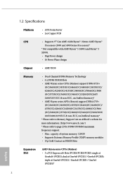
1.2 Specifications Platform CPU • ATX Form Factor • 2oz Copper PCB • Supports 3rd Gen AMD AM4 Ryzen™ / future AMD Ryzen™ Processors (3000 and 4000 Series Processors)* * Not compatible with AMD Ryzen™ 5 3400G and Ryzen™ 3 3200G. • Digi Power design • 16 Power Phase design Chipset • AMD B550 Memory • Dual Channel DDR4 Memory Technology • 4 x DDR4 DIMM Slots • AMD Ryzen series CPUs (Matisse) support DDR4 4733+ (OC)/4600(OC...
1.2 Specifications Platform CPU • ATX Form Factor • 2oz Copper PCB • Supports 3rd Gen AMD AM4 Ryzen™ / future AMD Ryzen™ Processors (3000 and 4000 Series Processors)* * Not compatible with AMD Ryzen™ 5 3400G and Ryzen™ 3 3200G. • Digi Power design • 16 Power Phase design Chipset • AMD B550 Memory • Dual Channel DDR4 Memory Technology • 4 x DDR4 DIMM Slots • AMD Ryzen series CPUs (Matisse) support DDR4 4733+ (OC)/4600(OC...

User Manual
Page 10
... HDMI monitor is occupied, PCIE5 will downgrade to 16GB. * The Max shared memory 16GB requires 32GB system memory installed. • Dual graphics output: support HDMI and DisplayPort 1.4 ports by CPU • DirectX 12, Pixel Shader 5.0 • Shared memory default 2GB. triple at Gen3x8 (PCIE1) / Gen3x8 (PCIE3); resolution up to x2 mode. * Supports NVMe SSD as boot disks • 2 x PCI Express 3.0 x1 Slots • Supports AMD Quad CrossFireXTM, 3-Way CrossFireXTM and CrossFireXTM • 1 x Vertical M.2 Socket (Key...
... HDMI monitor is occupied, PCIE5 will downgrade to 16GB. * The Max shared memory 16GB requires 32GB system memory installed. • Dual graphics output: support HDMI and DisplayPort 1.4 ports by CPU • DirectX 12, Pixel Shader 5.0 • Shared memory default 2GB. triple at Gen3x8 (PCIE1) / Gen3x8 (PCIE3); resolution up to x2 mode. * Supports NVMe SSD as boot disks • 2 x PCI Express 3.0 x1 Slots • Supports AMD Quad CrossFireXTM, 3-Way CrossFireXTM and CrossFireXTM • 1 x Vertical M.2 Socket (Key...

User Manual
Page 12
...USB3_1_2 ports. • 2 x USB 2.0 Ports (Supports ESD Protection) • 1 x RJ-45 LAN Port with LED (ACT/LINK LED and SPEED LED) • 1 x Clear CMOS Button • 1 x BIOS Flashback Button • HD Audio Jacks: Rear Speaker / Central / Bass / Line in / Front Speaker / Microphone (Gold Audio Jacks) Storage • 4 x SATA3 6.0 Gb/s Connectors, support RAID (RAID 0, RAID 1 and RAID 10), NCQ, AHCI and Hot Plug • 4 x SATA3 6.0 Gb/s Connectors by ASMedia ASM1061, support NCQ, AHCI and Hot Plug • 1 x Hyper M.2 Socket (M2_1), supports M Key type 2242/2260/2280 M.2 PCI Express...
...USB3_1_2 ports. • 2 x USB 2.0 Ports (Supports ESD Protection) • 1 x RJ-45 LAN Port with LED (ACT/LINK LED and SPEED LED) • 1 x Clear CMOS Button • 1 x BIOS Flashback Button • HD Audio Jacks: Rear Speaker / Central / Bass / Line in / Front Speaker / Microphone (Gold Audio Jacks) Storage • 4 x SATA3 6.0 Gb/s Connectors, support RAID (RAID 0, RAID 1 and RAID 10), NCQ, AHCI and Hot Plug • 4 x SATA3 6.0 Gb/s Connectors by ASMedia ASM1061, support NCQ, AHCI and Hot Plug • 1 x Hyper M.2 Socket (M2_1), supports M Key type 2242/2260/2280 M.2 PCI Express...

User Manual
Page 13
...Panel Type C USB 3.2 Gen2 Header (Supports ESD Protection) • 1 x Dr. Debug with LED • 1 x Power Button with LED • 1 x Reset Button with LED • 1 x Clear CMOS Button • AMI UEFI Legal BIOS with GUI support • Supports "Plug and Play" • ACPI 5.1 compliance wake up events • Supports jumperfree • SMBIOS 2.3 support • CPU, CPU VDDCR_SOC, DRAM, VPPM, VTT_DDR Offset, CPU VDD 1.8 Voltage Multi-adjustment English 6 BIOS Feature • 5 x Chassis/Water Pump Fan Connectors (4-pin) (Smart Fan Speed Control) * The Chassis/Water Pump Fan supports...
...Panel Type C USB 3.2 Gen2 Header (Supports ESD Protection) • 1 x Dr. Debug with LED • 1 x Power Button with LED • 1 x Reset Button with LED • 1 x Clear CMOS Button • AMI UEFI Legal BIOS with GUI support • Supports "Plug and Play" • ACPI 5.1 compliance wake up events • Supports jumperfree • SMBIOS 2.3 support • CPU, CPU VDDCR_SOC, DRAM, VPPM, VTT_DDR Offset, CPU VDD 1.8 Voltage Multi-adjustment English 6 BIOS Feature • 5 x Chassis/Water Pump Fan Connectors (4-pin) (Smart Fan Speed Control) * The Chassis/Water Pump Fan supports...
User Manual
Page 15
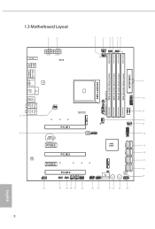
... bit, 288-pin module) D I S P L AY 1 HDMI1 Bottom: Optical SPDIF Top: USB 3.2 Gen1 USB1 USB2 USB3 USB4 LAN USB 2.0 T: USB1 B: USB2 Top: 2.5GLAN (I225V) USB 3.2 Gen2 T: USB31_TA_1 B: USB31_TC_1 CHA_FAN3 /WP SOCKET AM4 1 USB31_TC_2 USB3_7_8 Central/Bass LINE IN Center: REAR SPK Top: Center: FRONT Bottom: MIC IN 33 M2_1 PCIE1 CHA_FAN4 /WP CHA_FAN5 /WP 1 USB3_5_6 32 CMOS Battery BIOS SPI_TPM_J1 ROM 1 PCIE2 AMD B550 SATA3_1_2...
... bit, 288-pin module) D I S P L AY 1 HDMI1 Bottom: Optical SPDIF Top: USB 3.2 Gen1 USB1 USB2 USB3 USB4 LAN USB 2.0 T: USB1 B: USB2 Top: 2.5GLAN (I225V) USB 3.2 Gen2 T: USB31_TA_1 B: USB31_TC_1 CHA_FAN3 /WP SOCKET AM4 1 USB31_TC_2 USB3_7_8 Central/Bass LINE IN Center: REAR SPK Top: Center: FRONT Bottom: MIC IN 33 M2_1 PCIE1 CHA_FAN4 /WP CHA_FAN5 /WP 1 USB3_5_6 32 CMOS Battery BIOS SPI_TPM_J1 ROM 1 PCIE2 AMD B550 SATA3_1_2...

User Manual
Page 16
...) 18 SATA3 Connectors (SATA3_A1_A2) 19 Clear CMOS Button (CLRCBTN2) 20 System Panel Header (PANEL1) 21 Power Button (PWRBTN1) 22 Reset Button (RSTBTN1) 23 Clear CMOS Jumper (CLRCMOS1) 24 USB 2.0 Header (USB_5_6) 25 USB 2.0 Header (USB_3_4) 26 Power LED and Speaker Header (SPK_PLED1) 27 Chassis/Water Pump Fan Connector (CHA_FAN1/WP) 28 Chassis/Water Pump Fan Connector (CHA_FAN2/WP) 29 RGB LED Header (RGB_LED1) 30 Addressable LED Header (ADDR_LED1) 31 Front Panel Audio Header (HD_AUDIO1) 32 SPI TPM Header (SPI_TPM_J1) 33 Chassis/Water Pump Fan Connector (CHA_FAN3/WP) B550 Taichi 9 English
...) 18 SATA3 Connectors (SATA3_A1_A2) 19 Clear CMOS Button (CLRCBTN2) 20 System Panel Header (PANEL1) 21 Power Button (PWRBTN1) 22 Reset Button (RSTBTN1) 23 Clear CMOS Jumper (CLRCMOS1) 24 USB 2.0 Header (USB_5_6) 25 USB 2.0 Header (USB_3_4) 26 Power LED and Speaker Header (SPK_PLED1) 27 Chassis/Water Pump Fan Connector (CHA_FAN1/WP) 28 Chassis/Water Pump Fan Connector (CHA_FAN2/WP) 29 RGB LED Header (RGB_LED1) 30 Addressable LED Header (ADDR_LED1) 31 Front Panel Audio Header (HD_AUDIO1) 32 SPI TPM Header (SPI_TPM_J1) 33 Chassis/Water Pump Fan Connector (CHA_FAN3/WP) B550 Taichi 9 English

User Manual
Page 33
... the power supply is switched off or the power cord is used for PCI Express x1 lane width cards. PCIE5 (PCIe 3.0 x16 slot) is unplugged. PCIE3 (PCIe 4.0 x16 slot) is used for PCI Express x4 lane width graphics cards. * If PCIE2 or PCIE4 is used for the card before you start the installation. PCIE4 (PCIe 3.0 x1 slot) is occupied, PCIE5 will downgrade to x2 mode. Before installing an expansion card, please make necessary hardware settings for PCI Express x1...
... the power supply is switched off or the power cord is used for PCI Express x1 lane width cards. PCIE5 (PCIe 3.0 x16 slot) is unplugged. PCIE3 (PCIe 4.0 x16 slot) is used for PCI Express x4 lane width graphics cards. * If PCIE2 or PCIE4 is used for the card before you start the installation. PCIE4 (PCIe 3.0 x1 slot) is occupied, PCIE5 will downgrade to x2 mode. Before installing an expansion card, please make necessary hardware settings for PCI Express x1...

User Manual
Page 37
... IntA_PB_D+ IntA_PB_D- GND IntA_PB_SSTX+ IntA_PB_SSTX- These eight SATA3 connectors support SATA data cables for internal storage devices with up to this motherboard. Please connect the chassis power LED and the chassis speaker to 6.0 Gb/s data transfer rate. *To minimize the boot time, use AMD B550 SATA ports (SATA3_1) for your SSDs. SATA3_A2 SATA3_A4 SATA3_4 SATA3_2 SATA3_A1 SATA3_A3 SATA3_3 SATA3_1 USB 2.0 Headers (9-pin USB_3_4) (see p.8, No. 25) (9-pin USB_5_6) (see p.8, No. 10) Vbus IntA_PA_SSRXIntA_PA_SSRX+ GND...
... IntA_PB_D+ IntA_PB_D- GND IntA_PB_SSTX+ IntA_PB_SSTX- These eight SATA3 connectors support SATA data cables for internal storage devices with up to this motherboard. Please connect the chassis power LED and the chassis speaker to 6.0 Gb/s data transfer rate. *To minimize the boot time, use AMD B550 SATA ports (SATA3_1) for your SSDs. SATA3_A2 SATA3_A4 SATA3_4 SATA3_2 SATA3_A1 SATA3_A3 SATA3_3 SATA3_1 USB 2.0 Headers (9-pin USB_3_4) (see p.8, No. 25) (9-pin USB_5_6) (see p.8, No. 10) Vbus IntA_PA_SSRXIntA_PA_SSRX+ GND...

User Manual
Page 40
To use a 4-pin ATX power supply, please plug it along Pin 1 and Pin 5. *Connecting an ATX 12V 8-pin cable to ATX12V2 is optional. *Warning: Please make sure that the power cable connected is for further instructions on these two headers. 33 English RGB LED Headers (4-pin RGB_LED1) (see p.8, No. 29) (4-pin RGB_LED2) (see p.8, No. 5) 1 12V G R B These two RGB headers are used to connect RGB LED extension cable which can securely store keys, digital certificates, passwords, and data. B550 Taichi ATX 12V Power 8 5 Connectors (8-pin ATX12V1) 4 1 (see...
To use a 4-pin ATX power supply, please plug it along Pin 1 and Pin 5. *Connecting an ATX 12V 8-pin cable to ATX12V2 is optional. *Warning: Please make sure that the power cable connected is for further instructions on these two headers. 33 English RGB LED Headers (4-pin RGB_LED1) (see p.8, No. 29) (4-pin RGB_LED2) (see p.8, No. 5) 1 12V G R B These two RGB headers are used to connect RGB LED extension cable which can securely store keys, digital certificates, passwords, and data. B550 Taichi ATX 12V Power 8 5 Connectors (8-pin ATX12V1) 4 1 (see...

User Manual
Page 43
... BIOS file to your USB drive to power on the system. 6. Plug the 24 pin power connector to flash the BIOS. English USB BIOS Flashback port 36 To use the USB BIOS Flashback function, Please follow the steps below. 1. Download the latest BIOS file from the zip file. 4. Then plug your USB flash drive. Press the BIOS Flashback Switch for about three seconds. BIOS Flashback Button (BIOS_FB1) (see p.10, No. 1) BIOS Flashback Switch allows users to the motherboard. Please make sure that the BIOS...
... BIOS file to your USB drive to power on the system. 6. Plug the 24 pin power connector to flash the BIOS. English USB BIOS Flashback port 36 To use the USB BIOS Flashback function, Please follow the steps below. 1. Download the latest BIOS file from the zip file. 4. Then plug your USB flash drive. Press the BIOS Flashback Switch for about three seconds. BIOS Flashback Button (BIOS_FB1) (see p.10, No. 1) BIOS Flashback Switch allows users to the motherboard. Please make sure that the BIOS...
User Manual
Page 50
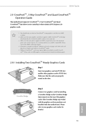
... a 16-pipe card, both cards will operate as 12-pipe cards while in CrossFireXTM mode. 5. Please refer to AMD graphics card manuals for details. 4. You should only use a AMD certified PSU. Download the drivers from the AMD's website: www.amd.com 3. If you to install up to your system requires. Make sure that your graphics card driver supports AMD CrossFireXTM technology. B550 Taichi 2.9 CrossFireXTM , 3-Way CrossFireXTM and Quad CrossFireXTM Operation Guide This motherboard supports CrossFireXTM, 3-way...
... a 16-pipe card, both cards will operate as 12-pipe cards while in CrossFireXTM mode. 5. Please refer to AMD graphics card manuals for details. 4. You should only use a AMD certified PSU. Download the drivers from the AMD's website: www.amd.com 3. If you to install up to your system requires. Make sure that your graphics card driver supports AMD CrossFireXTM technology. B550 Taichi 2.9 CrossFireXTM , 3-Way CrossFireXTM and Quad CrossFireXTM Operation Guide This motherboard supports CrossFireXTM, 3-way...
User Manual
Page 53
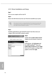
... GPU number according to installation. Please check AMD's website for AMD driver updates. Step 5 In the left pane, click Performance and then AMD CrossFireXTM. The Catalyst Uninstaller is an optional download. We recommend using this utility to uninstall any VGA drivers installed in the Windows® system tray. Step 3 Install the required drivers and CATALYST Control Center then restart your system. Then select Enable AMD CrossFireX and click Apply...
... GPU number according to installation. Please check AMD's website for AMD driver updates. Step 5 In the left pane, click Performance and then AMD CrossFireXTM. The Catalyst Uninstaller is an optional download. We recommend using this utility to uninstall any VGA drivers installed in the Windows® system tray. Step 3 Install the required drivers and CATALYST Control Center then restart your system. Then select Enable AMD CrossFireX and click Apply...
User Manual
Page 60
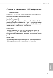
... drivers you install can work properly. The CD automatically displays the Main Menu if "AUTORUN" is enabled in the Support CD to your system will be auto-detected and listed on the file "ASRSETUP.EXE" in your CD-ROM drive. Drivers Menu The drivers compatible to display the menu. Running The Support CD To begin using the support CD, insert the CD into your computer. Utilities Menu The Utilities Menu shows the application software that enhance the motherboard...
... drivers you install can work properly. The CD automatically displays the Main Menu if "AUTORUN" is enabled in the Support CD to your system will be auto-detected and listed on the file "ASRSETUP.EXE" in your CD-ROM drive. Drivers Menu The drivers compatible to display the menu. Running The Support CD To begin using the support CD, insert the CD into your computer. Utilities Menu The Utilities Menu shows the application software that enhance the motherboard...

User Manual
Page 77
... instability or failure. When overclocking also the PCIe, PCI, SATA and USB busses will be set to [Manual], the multiplier and voltage will be overcloked which may be combined with a custom CPU core frequency. Final result is constantly being updated, the following UEFI setup screens and descriptions are for idle cores (e.g. Warning! cc6 sleep) remain active. 70 English CPU Frequency and Voltage(VID) Change If this item is connected via the onboard D-Bus/VGA connector. Please install an...
... instability or failure. When overclocking also the PCIe, PCI, SATA and USB busses will be set to [Manual], the multiplier and voltage will be overcloked which may be combined with a custom CPU core frequency. Final result is constantly being updated, the following UEFI setup screens and descriptions are for idle cores (e.g. Warning! cc6 sleep) remain active. 70 English CPU Frequency and Voltage(VID) Change If this item is connected via the onboard D-Bus/VGA connector. Please install an...


