
RAID Installation Guide
Page 2
You may install SATA hard disks on SATA ports. 2 Guide to the Intel southbridge chipset that your motherboard adopts. 1. Please read the RAID configurations in this motherboard for internal storage devices. This section will guide you how to create RAID on this guide carefully according to SATA Hard Disks Installation 1.1 Serial ATA (SATA) Hard Disks Installation Intel chipset supports Serial ATA (SATA) hard disks with RAID functions, including RAID 0, RAID 1, RAID 5, RAID 10 and Intel Rapid Storage.
You may install SATA hard disks on SATA ports. 2 Guide to the Intel southbridge chipset that your motherboard adopts. 1. Please read the RAID configurations in this motherboard for internal storage devices. This section will guide you how to create RAID on this guide carefully according to SATA Hard Disks Installation 1.1 Serial ATA (SATA) Hard Disks Installation Intel chipset supports Serial ATA (SATA) hard disks with RAID functions, including RAID 0, RAID 1, RAID 5, RAID 10 and Intel Rapid Storage.

RAID Installation Guide
Page 3
For optimal performance, please install identical drives of RAID This motherboard adopts Intel southbridge chipset that optimizes two identical hard disk drives to read and write data in the other drive if one drive fails. 3 RAID 0 (...
For optimal performance, please install identical drives of RAID This motherboard adopts Intel southbridge chipset that optimizes two identical hard disk drives to read and write data in the other drive if one drive fails. 3 RAID 0 (...

RAID Installation Guide
Page 14
... boot. 14 STEP 1: Copy Intel® RAID drivers into a USB flash disk You can download the drivers from ASRock's website and unzip the files into a USB flash disk or copy the files from ASRock's motherboard support CD. (Please copy the files under the following directory: 32 bit: ..\i386\Win7_Intel.. 64-bit: ..\AMD64\Win7...
... boot. 14 STEP 1: Copy Intel® RAID drivers into a USB flash disk You can download the drivers from ASRock's website and unzip the files into a USB flash disk or copy the files from ASRock's motherboard support CD. (Please copy the files under the following directory: 32 bit: ..\i386\Win7_Intel.. 64-bit: ..\AMD64\Win7...

RAID Installation Guide
Page 16
... 64-bit, install the hotfix kb2505454. (This may take more time to fix this problem. Disk volume > 2TB), it may take about 5 minutes to install motherboard drivers and utilities. 16 Windows® 10 64-bit: A.
... 64-bit, install the hotfix kb2505454. (This may take more time to fix this problem. Disk volume > 2TB), it may take about 5 minutes to install motherboard drivers and utilities. 16 Windows® 10 64-bit: A.

User Manual
Page 2
...subject to change without notice, and should not be reproduced, transcribed, transmitted, or translated in any form or by ASRock. Copyright Notice: No part of this motherboard contains Perchlorate, a toxic substance controlled in advance. In no responsibility for loss of profits, loss of business, ...loss of data, interruption of business and the like), even if ASRock has been advised of the possibility of their ...
...subject to change without notice, and should not be reproduced, transcribed, transmitted, or translated in any form or by ASRock. Copyright Notice: No part of this motherboard contains Perchlorate, a toxic substance controlled in advance. In no responsibility for loss of profits, loss of business, ...loss of data, interruption of business and the like), even if ASRock has been advised of the possibility of their ...

User Manual
Page 4
Contents Chapter 1 Introduction 1 1.1 Package Contents 1 1.2 Specifications 2 1.3 Motherboard Layout 7 1.4 I/O Panel 9 Chapter 2 Installation 10 2.1 Installing the CPU 11 2.2 Installing the CPU Fan and Heatsink 14 2.3 Installing Memory Modules (DIMM) 15 2.4 Expansion Slots (PCI Express ... 27 2.9 M.2_SSD (NGFF) Module Installation Guide (M2_1) 29 2.10 M.2_SSD (NGFF) Module Installation Guide (M2_2) 32 Chapter 3 Software and Utilities Operation 36 3.1 Installing Drivers 36 3.2 ASRock Motherboard Utility (A-Tuning) 37 3.3 ASRock Live Update & APP Shop 40
Contents Chapter 1 Introduction 1 1.1 Package Contents 1 1.2 Specifications 2 1.3 Motherboard Layout 7 1.4 I/O Panel 9 Chapter 2 Installation 10 2.1 Installing the CPU 11 2.2 Installing the CPU Fan and Heatsink 14 2.3 Installing Memory Modules (DIMM) 15 2.4 Expansion Slots (PCI Express ... 27 2.9 M.2_SSD (NGFF) Module Installation Guide (M2_1) 29 2.10 M.2_SSD (NGFF) Module Installation Guide (M2_2) 32 Chapter 3 Software and Utilities Operation 36 3.1 Installing Drivers 36 3.2 ASRock Motherboard Utility (A-Tuning) 37 3.3 ASRock Live Update & APP Shop 40
User Manual
Page 7
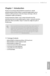
... be available on ASRock's website as well. ASRock website http://www.asrock.com. 1.1 Package Contents • ASRock B460M Pro4 Motherboard (Micro ATX Form Factor) • ASRock B460M Pro4 Quick Installation Guide • ASRock B460M Pro4 Support CD • 2 x Serial ATA (SATA) Data Cables (Optional) • 3 x Screws for M.2 Sockets (Optional) • 1 x Standoff for purchasing ASRock B460M Pro4 motherboard, a reliable motherboard produced under ASRock's consistently stringent quality control. B460M Pro4 Chapter 1 Introduction Thank...
... be available on ASRock's website as well. ASRock website http://www.asrock.com. 1.1 Package Contents • ASRock B460M Pro4 Motherboard (Micro ATX Form Factor) • ASRock B460M Pro4 Quick Installation Guide • ASRock B460M Pro4 Support CD • 2 x Serial ATA (SATA) Data Cables (Optional) • 3 x Screws for M.2 Sockets (Optional) • 1 x Standoff for purchasing ASRock B460M Pro4 motherboard, a reliable motherboard produced under ASRock's consistently stringent quality control. B460M Pro4 Chapter 1 Introduction Thank...

User Manual
Page 13
USB2.0 T: USB1 B: USB2 PS2 Keyboard /Mouse 1.3 Motherboard Layout 1 ATX12V1 B460M Pro4 2 3 45 CPU_FAN1 CPU_FAN2/WP ADDR_LED1 RGB_LED1 6 1 7 1 VGA1 HDMI1 Display1 ATXPWR1 DDR4_A1 (64 bit, 288-pin module) DDR4_A2 (64 bit, 288-pin module) DDR4_B1 (64 bit, ...
USB2.0 T: USB1 B: USB2 PS2 Keyboard /Mouse 1.3 Motherboard Layout 1 ATX12V1 B460M Pro4 2 3 45 CPU_FAN1 CPU_FAN2/WP ADDR_LED1 RGB_LED1 6 1 7 1 VGA1 HDMI1 Display1 ATXPWR1 DDR4_A1 (64 bit, 288-pin module) DDR4_A2 (64 bit, 288-pin module) DDR4_B1 (64 bit, ...

User Manual
Page 16
... • Hold components by the edges and do not touch the ICs. • Whenever you uninstall any motherboard settings. • Make sure to the motherboard's components, NEVER place your chassis to ensure that comes with the components. • When placing screws to ... damage from static electricity to unplug the power cord before you install the motherboard, study the configuration of the following precautions before installing or removing the motherboard components. Before you install motherboard components or change any components, place them on a carpet. Pre-installation ...
... • Hold components by the edges and do not touch the ICs. • Whenever you uninstall any motherboard settings. • Make sure to the motherboard's components, NEVER place your chassis to ensure that comes with the components. • When placing screws to ... damage from static electricity to unplug the power cord before you install the motherboard, study the configuration of the following precautions before installing or removing the motherboard components. Before you install motherboard components or change any components, place them on a carpet. Pre-installation ...

User Manual
Page 19
The cover must be placed if you wish to return the motherboard for after service. 13 English B460M Pro4 Please save and replace the cover if the processor is removed.
The cover must be placed if you wish to return the motherboard for after service. 13 English B460M Pro4 Please save and replace the cover if the processor is removed.
User Manual
Page 21
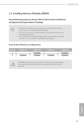
B460M Pro4 2.3 Installing Memory Modules (DIMM) This motherboard provides four 288-pin DDR4 (Double Data Rate 4) DIMM slots, and supports Dual Channel Memory Technology. 1. It is not allowed to the motherboard and the DIMM if you always need to activate Dual Channel Memory Technology with only one correct orientation....DDR4_A2 Populated Populated DDR4_B1 Populated DDR4_B2 Populated Populated The DIMM only fits in one or three memory module installed. 3. otherwise, this motherboard and DIMM may be damaged. For dual channel configuration, you force the DIMM into a DDR4 slot;
B460M Pro4 2.3 Installing Memory Modules (DIMM) This motherboard provides four 288-pin DDR4 (Double Data Rate 4) DIMM slots, and supports Dual Channel Memory Technology. 1. It is not allowed to the motherboard and the DIMM if you always need to activate Dual Channel Memory Technology with only one correct orientation....DDR4_A2 Populated Populated DDR4_B1 Populated DDR4_B2 Populated Populated The DIMM only fits in one or three memory module installed. 3. otherwise, this motherboard and DIMM may be damaged. For dual channel configuration, you force the DIMM into a DDR4 slot;

User Manual
Page 23
... off or the power cord is used for PCI Express x1 lane width cards. English 17 B460M Pro4 2.4 Expansion Slots (PCI Express Slots) There are 3 PCI Express slots on the motherboard. PCIe Slot Configurations Single Graphics Card Two Graphics Cards in CrossFireXTM Mode PCIE1 x16 x16 PCIE3... N/A x4 For a better thermal environment, please connect a chassis fan to the motherboard's chassis fan connector (CHA_FAN1/WP, CHA_FAN2/WP or CHA_FAN3/WP) when using multiple graphics cards. Before installing an expansion card, please...
... off or the power cord is used for PCI Express x1 lane width cards. English 17 B460M Pro4 2.4 Expansion Slots (PCI Express Slots) There are 3 PCI Express slots on the motherboard. PCIe Slot Configurations Single Graphics Card Two Graphics Cards in CrossFireXTM Mode PCIE1 x16 x16 PCIE3... N/A x4 For a better thermal environment, please connect a chassis fan to the motherboard's chassis fan connector (CHA_FAN1/WP, CHA_FAN2/WP or CHA_FAN3/WP) when using multiple graphics cards. Before installing an expansion card, please...

User Manual
Page 25
.... PLED (System Power LED): Connect to this header. 19 Press the reset switch to restart the computer if the computer freezes and fails to the motherboard. A front panel module mainly consists of power switch, reset switch, power LED, hard drive activity LED, speaker and etc. English Chassis Intrusion and Speaker Header... system is in S1/S3 sleep state. Do NOT place jumper caps over the headers and connectors will cause permanent damage to perform a normal restart. B460M Pro4 2.6 Onboard Headers and Connectors Onboard headers and connectors are matched correctly.
.... PLED (System Power LED): Connect to this header. 19 Press the reset switch to restart the computer if the computer freezes and fails to the motherboard. A front panel module mainly consists of power switch, reset switch, power LED, hard drive activity LED, speaker and etc. English Chassis Intrusion and Speaker Header... system is in S1/S3 sleep state. Do NOT place jumper caps over the headers and connectors will cause permanent damage to perform a normal restart. B460M Pro4 2.6 Onboard Headers and Connectors Onboard headers and connectors are matched correctly.

User Manual
Page 26
...(9-pin USB5_6) (see p.7, No. 20) USB_PWR PP+ GND DUMMY 1 GND P+ PUSB_PWR There are two USB 2.0 headers on this motherboard.Each USB 2.0 header can support two ports. Front Panel Audio Header (9-pin HD_AUDIO1) (see p.7, No. 9) Vbus IntA_PA_SSRXIntA_PA_SSRX+ GND IntA_PA_SSTXIntA_PA_SSTX...+ GND IntA_PA_DIntA_PA_D+ Vbus IntA_PB_SSRXIntA_PB_SSRX+ GND IntA_PB_SSTXIntA_PB_SSTX+ GND IntA_PB_DIntA_PB_D+ Dummy 1 There is one USB 3.2 Gen1 header on this motherboard. English 20 If M2_2 is for internal storage devices with up to the front audio panel. USB 3.2 Gen1 Header (...
...(9-pin USB5_6) (see p.7, No. 20) USB_PWR PP+ GND DUMMY 1 GND P+ PUSB_PWR There are two USB 2.0 headers on this motherboard.Each USB 2.0 header can support two ports. Front Panel Audio Header (9-pin HD_AUDIO1) (see p.7, No. 9) Vbus IntA_PA_SSRXIntA_PA_SSRX+ GND IntA_PA_SSTXIntA_PA_SSTX...+ GND IntA_PA_DIntA_PA_D+ Vbus IntA_PB_SSRXIntA_PB_SSRX+ GND IntA_PB_SSTXIntA_PB_SSTX+ GND IntA_PB_DIntA_PB_D+ Dummy 1 There is one USB 3.2 Gen1 header on this motherboard. English 20 If M2_2 is for internal storage devices with up to the front audio panel. USB 3.2 Gen1 Header (...

User Manual
Page 27
... Fan Connector (4-pin CPU_FAN2/WP) (see p.7, No. 3) FAN_SPEED This motherboard pro- If you use an AC'97 audio panel, please install it to Pin 1-3. English 21 B460M Pro4 1. High Definition Audio supports Jack Sensing, but the panel wire on the...) (4-pin CHA_FAN3/WP) (see p.7, No. 14) 1 GND 2 FAN_VOLTAGE 3 CHA_FAN_SPEED 4 FAN_SPEED_CONTROL 4 3 21 GND FAN_VOLTAGE_CONTROL FAN_SPEED FAN_SPEED_CONTROL This motherboard provides three 4-Pin water cooling chassis fan connectors. To activate the front mic, go to Ground (GND). Please follow the instructions in the Realtek...
... Fan Connector (4-pin CPU_FAN2/WP) (see p.7, No. 3) FAN_SPEED This motherboard pro- If you use an AC'97 audio panel, please install it to Pin 1-3. English 21 B460M Pro4 1. High Definition Audio supports Jack Sensing, but the panel wire on the...) (4-pin CHA_FAN3/WP) (see p.7, No. 14) 1 GND 2 FAN_VOLTAGE 3 CHA_FAN_SPEED 4 FAN_SPEED_CONTROL 4 3 21 GND FAN_VOLTAGE_CONTROL FAN_SPEED FAN_SPEED_CONTROL This motherboard provides three 4-Pin water cooling chassis fan connectors. To activate the front mic, go to Ground (GND). Please follow the instructions in the Realtek...

User Manual
Page 28
... PCIE3 (default slot). To use a 4 1 4-pin ATX power supply, please plug it along Pin 1 and Pin 5. ATX Power Connector (24-pin ATXPWR1) (see p.7, No. 1) 8 5 This motherboard pro- ATX 12V Power Connector (8-pin ATX12V1) (see p.7, No. 8) 12 24 1 13 This...
... PCIE3 (default slot). To use a 4 1 4-pin ATX power supply, please plug it along Pin 1 and Pin 5. ATX Power Connector (24-pin ATXPWR1) (see p.7, No. 1) 8 5 This motherboard pro- ATX 12V Power Connector (8-pin ATX12V1) (see p.7, No. 8) 12 24 1 13 This...

User Manual
Page 30
... Bridge Step 2 Connect two graphics cards by installing a CrossFire Bridge on the CrossFire Bridge Interconnects on the slots. 2.7 CrossFireXTM and Quad CrossFireXTM Operation Guide This motherboard supports CrossFireXTM and Quad CrossFireXTM that allows you pair a 12-pipe CrossFireXTM Edition card with this...
... Bridge Step 2 Connect two graphics cards by installing a CrossFire Bridge on the CrossFire Bridge Interconnects on the slots. 2.7 CrossFireXTM and Quad CrossFireXTM Operation Guide This motherboard supports CrossFireXTM and Quad CrossFireXTM that allows you pair a 12-pipe CrossFireXTM Edition card with this...

User Manual
Page 36
... into place. English C B A 20o 30 NUT2 NUT1 Step 7 Tighten the screw with a screwdriver to use the default nut. C B A C B A C B A Step 4 Move the standoff based on the motherboard. The standoff is placed at the nut location C by hand. Please be used.
... into place. English C B A 20o 30 NUT2 NUT1 Step 7 Tighten the screw with a screwdriver to use the default nut. C B A C B A C B A Step 4 Move the standoff based on the motherboard. The standoff is placed at the nut location C by hand. Please be used.

User Manual
Page 39
B A B A B A B460M Pro4 Step 3 Move the standoff based on the motherboard. Hand tighten the standoff into the M.2 slot. Step 4 Peel off the yellow protective film on the nut to secure the module into place. Please be ...
B A B A B A B460M Pro4 Step 3 Move the standoff based on the motherboard. Hand tighten the standoff into the M.2 slot. Step 4 Peel off the yellow protective film on the nut to secure the module into place. Please be ...
User Manual
Page 42
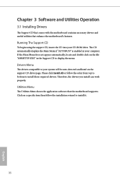
Utilities Menu The Utilities Menu shows the application software that enhance the motherboard's features. Click on the support CD driver page. Please click Install All or follow the installation wizard to install those required drivers. The CD automatically ... your computer. Drivers Menu The drivers compatible to display the menu. Chapter 3 Software and Utilities Operation 3.1 Installing Drivers The Support CD that comes with the motherboard contains necessary drivers and useful utilities that the...
Utilities Menu The Utilities Menu shows the application software that enhance the motherboard's features. Click on the support CD driver page. Please click Install All or follow the installation wizard to install those required drivers. The CD automatically ... your computer. Drivers Menu The drivers compatible to display the menu. Chapter 3 Software and Utilities Operation 3.1 Installing Drivers The Support CD that comes with the motherboard contains necessary drivers and useful utilities that the...

