
RAID Installation Guide
Page 8
.... D. Please install the DVD-ROM. Follow instructions to enter UEFI setup utility. Click to find the driver inside your USB flash disk. C. STEP 3.2: Download driver from ASRock's website and unzip the file into your USB flash drive. 8 Go to finish the configuration. STEP 4: Windows installation A. B. Insert the Support CD into one of the...
.... D. Please install the DVD-ROM. Follow instructions to enter UEFI setup utility. Click to find the driver inside your USB flash disk. C. STEP 3.2: Download driver from ASRock's website and unzip the file into your USB flash drive. 8 Go to finish the configuration. STEP 4: Windows installation A. B. Insert the Support CD into one of the...

RAID Installation Guide
Page 9
Select "AMD-RAID Bottom Device" and then click . E. Select "AMD-RAID Controller storport" and then click . G. Click again to find the driver inside your USB flash drive. Please select the correct driver for your USB flash drive. 9 For 64bit OS, the driver is under /AMD64 directly. F. D. Click again to find the driver inside your Windows version (Windows 10). C. For 32bit OS, the driver is under /I386 directory.
Select "AMD-RAID Bottom Device" and then click . E. Select "AMD-RAID Controller storport" and then click . G. Click again to find the driver inside your USB flash drive. Please select the correct driver for your USB flash drive. 9 For 64bit OS, the driver is under /AMD64 directly. F. D. Click again to find the driver inside your Windows version (Windows 10). C. For 32bit OS, the driver is under /I386 directory.

RAID Installation Guide
Page 12
...Follow instructions to delete the existing disk arrays before creating a new array. Please download the "SATA Floppy Imaged driver" from ASRock's website A. Go to AdvancedRAIDXpert2 Configuration UtilityArray ManagementCreate Array Select Physical DisksCheck ... choose either STEP2.1 or STEP2.2 to enter UEFI setup utility. B. Go to exit. STEP 2.2: Download driver from ASRock's website and unzip the file into one of the USB port. H. Click to save to Tools Easy RAID Installer F. A. Please install the DVD-ROM. Insert the...
...Follow instructions to delete the existing disk arrays before creating a new array. Please download the "SATA Floppy Imaged driver" from ASRock's website A. Go to AdvancedRAIDXpert2 Configuration UtilityArray ManagementCreate Array Select Physical DisksCheck ... choose either STEP2.1 or STEP2.2 to enter UEFI setup utility. B. Go to exit. STEP 2.2: Download driver from ASRock's website and unzip the file into one of the USB port. H. Click to save to Tools Easy RAID Installer F. A. Please install the DVD-ROM. Insert the...

RAID Installation Guide
Page 13
For 64bit OS, the driver is under /AMD64 directly. Click to find the driver inside your Windows version (Windows 10). D. STEP 3: Windows installation A. Please select the correct driver for your USB flash drive. Select "AMD-RAID Bottom Device" and then click . 13 C. B. For 32bit OS, the driver is under /I386 directory. During Windows installation process, when Disk selection page show up, please click .
For 64bit OS, the driver is under /AMD64 directly. Click to find the driver inside your Windows version (Windows 10). D. STEP 3: Windows installation A. Please select the correct driver for your USB flash drive. Select "AMD-RAID Bottom Device" and then click . 13 C. B. For 32bit OS, the driver is under /I386 directory. During Windows installation process, when Disk selection page show up, please click .

RAID Installation Guide
Page 14
F. H. E. Click again to find the driver inside your USB flash drive. Click again to find the driver inside your USB flash drive. G. Select "AMD-RAID Controller storport" and then click . Select "AMD-RAID Config Device" and then click . 14
F. H. E. Click again to find the driver inside your USB flash drive. Click again to find the driver inside your USB flash drive. G. Select "AMD-RAID Controller storport" and then click . Select "AMD-RAID Config Device" and then click . 14

User Manual
Page 9
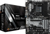
If either one of them is required to use , the others will be disabled. tection) • 1 x USB 3.1 Gen2 Type-C Port (10 Gb/s) (Supports ESD Pro- tection) • 4 x USB 3.1 Gen1 Ports (Supports ESD Protection) • 1 x RJ-45 LAN Port with Content Protection (Realtek ALC892 Audio Codec) * To configure 7.1 CH HD ... 802.3az • Supports PXE Rear Panel I/O • 1 x PS/2 Mouse/Keyboard Port • 1 x D-Sub Port • 1 x HDMI Port • 1 x DisplayPort 1.2 • 2 x USB 2.0 Ports (Supports ESD Protection) • 1 x USB 3.1 Gen2 Type-A Port (10 Gb/s) (Supports ESD Pro-
If either one of them is required to use , the others will be disabled. tection) • 1 x USB 3.1 Gen2 Type-C Port (10 Gb/s) (Supports ESD Pro- tection) • 4 x USB 3.1 Gen1 Ports (Supports ESD Protection) • 1 x RJ-45 LAN Port with Content Protection (Realtek ALC892 Audio Codec) * To configure 7.1 CH HD ... 802.3az • Supports PXE Rear Panel I/O • 1 x PS/2 Mouse/Keyboard Port • 1 x D-Sub Port • 1 x HDMI Port • 1 x DisplayPort 1.2 • 2 x USB 2.0 Ports (Supports ESD Protection) • 1 x USB 3.1 Gen2 Type-A Port (10 Gb/s) (Supports ESD Pro-
User Manual
Page 11
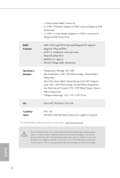
...8226; ErP/EuP ready (ErP/EuP ready power supply is required) * For detailed product information, please visit our website: http://www.asrock.com Please realize that there is a certain risk involved with multilingual GUI support • Supports "Plug and Play" • ACPI ...It should be done at your system. • 1 x Front Panel Audio Connector • 2 x USB 2.0 Headers (Support 4 USB 2.0 ports) (Supports ESD Protection) • 1 x USB 3.1 Gen1 Header (Supports 2 USB 3.1 Gen1 ports) (Supports ESD Protection) BIOS Feature • AMI UEFI Legal BIOS with overclocking, including ...
...8226; ErP/EuP ready (ErP/EuP ready power supply is required) * For detailed product information, please visit our website: http://www.asrock.com Please realize that there is a certain risk involved with multilingual GUI support • Supports "Plug and Play" • ACPI ...It should be done at your system. • 1 x Front Panel Audio Connector • 2 x USB 2.0 Headers (Support 4 USB 2.0 ports) (Supports ESD Protection) • 1 x USB 3.1 Gen1 Header (Supports 2 USB 3.1 Gen1 ports) (Supports ESD Protection) BIOS Feature • AMI UEFI Legal BIOS with overclocking, including ...
User Manual
Page 12
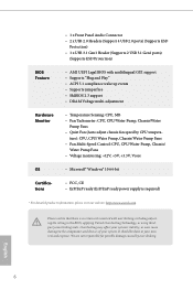
... 27 Top: LINE IN Center: FRONT Bottom: MIC IN USB 3.1 Gen2 T: USB31_TA_1 B: USB31_TC_1 USB 3.1 Gen1 T: USB1 B: USB2 USB 3.1 Gen1 T: USB3 B: USB4 CHA_FAN1/WP RJ-45 LAN BIOS ROM PCIE1 PCIE2 M2_1 1 Ultra M.2 PCIe Gen3 x4 USB3_5_6 Super I/O PCIE3 PCIE5 CMOS Battery PCIE4 B450 Pro4 AMD Promontory B450 M2_2 HD_AUDIO1 1 PCIE6 TPMS1 1 RGB_LED1 1 COM1 1 RoHS USB_1_2 1 SPK_PLED1...
... 27 Top: LINE IN Center: FRONT Bottom: MIC IN USB 3.1 Gen2 T: USB31_TA_1 B: USB31_TC_1 USB 3.1 Gen1 T: USB1 B: USB2 USB 3.1 Gen1 T: USB3 B: USB4 CHA_FAN1/WP RJ-45 LAN BIOS ROM PCIE1 PCIE2 M2_1 1 Ultra M.2 PCIe Gen3 x4 USB3_5_6 Super I/O PCIE3 PCIE5 CMOS Battery PCIE4 B450 Pro4 AMD Promontory B450 M2_2 HD_AUDIO1 1 PCIE6 TPMS1 1 RGB_LED1 1 COM1 1 RoHS USB_1_2 1 SPK_PLED1...
User Manual
Page 13
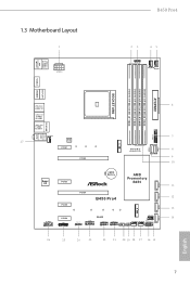
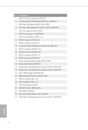
...) 3 AMD Fan LED Header (AMD_FAN_LED1) 4 CPU Fan / Waterpump Fan Connector (CPU_FAN2/WP) 5 CPU Fan Connector (CPU_FAN1) 6 ATX Power Connector (ATXPWR1) 7 USB 3.1 Gen1 Header (USB3_5_6) 8 SATA3 Connector (SATA3_2) 9 SATA3 Connector (SATA3_1) 10 2 x 288-pin DDR4 DIMM Slots (DDR4_A2, DDR4_B2) 11 SATA3 Connector (SATA3_A1...WP) 18 Chassis Fan / Waterpump Fan Connector (CHA_FAN2/WP) 19 Clear CMOS Jumper (CLRCMOS2) 20 Addressable LED Header (ADDR_LED1) 21 USB 2.0 Header (USB_3_4) 22 USB 2.0 Header (USB_1_2) 23 COM Port Header (COM1) 24 RGB LED Header (RGB_LED1) 25 TPM Header (TPMS1) 26 Front Panel...
...) 3 AMD Fan LED Header (AMD_FAN_LED1) 4 CPU Fan / Waterpump Fan Connector (CPU_FAN2/WP) 5 CPU Fan Connector (CPU_FAN1) 6 ATX Power Connector (ATXPWR1) 7 USB 3.1 Gen1 Header (USB3_5_6) 8 SATA3 Connector (SATA3_2) 9 SATA3 Connector (SATA3_1) 10 2 x 288-pin DDR4 DIMM Slots (DDR4_A2, DDR4_B2) 11 SATA3 Connector (SATA3_A1...WP) 18 Chassis Fan / Waterpump Fan Connector (CHA_FAN2/WP) 19 Clear CMOS Jumper (CLRCMOS2) 20 Addressable LED Header (ADDR_LED1) 21 USB 2.0 Header (USB_3_4) 22 USB 2.0 Header (USB_1_2) 23 COM Port Header (COM1) 24 RGB LED Header (RGB_LED1) 25 TPM Header (TPMS1) 26 Front Panel...

User Manual
Page 14
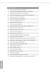
1.4 I/O Panel 1 2 B450 Pro4 4 3 5 13 12 11 9 8 7 6 10 No. Description 1 USB 2.0 Ports (USB56) 2 DisplayPort 1.2 3 LAN RJ-45 Port* 4 Line In (Light Blue)** 5 Front Speaker (Lime)** 6 Microphone (Pink)** 7 USB 3.1 Gen1 Ports (USB3_34) No. Please refer to the table below for the LAN port LED indications. Description 8 USB 3.1 Gen1 Ports (USB3_12) 9 USB 3.1 Gen2 Type-A Port (USB31_TA_1) 10 USB 3.1 Gen2 Type-C Port...
1.4 I/O Panel 1 2 B450 Pro4 4 3 5 13 12 11 9 8 7 6 10 No. Description 1 USB 2.0 Ports (USB56) 2 DisplayPort 1.2 3 LAN RJ-45 Port* 4 Line In (Light Blue)** 5 Front Speaker (Lime)** 6 Microphone (Pink)** 7 USB 3.1 Gen1 Ports (USB3_34) No. Please refer to the table below for the LAN port LED indications. Description 8 USB 3.1 Gen1 Ports (USB3_12) 9 USB 3.1 Gen2 Type-A Port (USB31_TA_1) 10 USB 3.1 Gen2 Type-C Port...
User Manual
Page 27
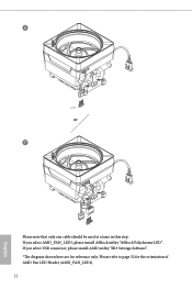
6 CPU_FAN1 +12V AMD_FAN_LED1 or 7 CPU_FAN1 AMD_FAN_LED1 USB_5 Please note that only one cable should be used at a time in this step. If you select AMD_FAN_LED1, please install ASRock utility "ASRock Polychrome LED". Please refer to page 32 for reference only. If you select USB connector, please install AMD utility "SR3 Settings Software". *The diagram shown here are for the orientation of AMD Fan LED Header (AMD_FAN_LED1). 22 English
6 CPU_FAN1 +12V AMD_FAN_LED1 or 7 CPU_FAN1 AMD_FAN_LED1 USB_5 Please note that only one cable should be used at a time in this step. If you select AMD_FAN_LED1, please install ASRock utility "ASRock Polychrome LED". Please refer to page 32 for reference only. If you select USB connector, please install AMD utility "SR3 Settings Software". *The diagram shown here are for the orientation of AMD Fan LED Header (AMD_FAN_LED1). 22 English

User Manual
Page 34
Please connect the chassis power LED and the chassis speaker to 6.0 Gb/s data transfer rate. * M2_2, SATA3_3 and SATA3_4 share lanes. USB 2.0 Headers (9-pin USB_1_2) (see p.7, No. 22) (9-pin USB_3_4) (see p.7, No. 21) USB_PWR PP+ GND DUMMY 1 GND P+ PUSB_PWR There are ... +5V 1 PLED+ PLED+ PLED- If either one header on this header. Each USB 3.1 Gen1 header can support two ports. Each USB 2.0 header can support two ports. 29 SATA3_1 SATA3_4 SATA3_3 SATA3_A2 SATA3_A1 SATA3_2 English B450 Pro4 Power LED and Speaker Header (7-pin SPK_PLED1) (see p.7, No. 15) Serial ATA3 Connectors...
Please connect the chassis power LED and the chassis speaker to 6.0 Gb/s data transfer rate. * M2_2, SATA3_3 and SATA3_4 share lanes. USB 2.0 Headers (9-pin USB_1_2) (see p.7, No. 22) (9-pin USB_3_4) (see p.7, No. 21) USB_PWR PP+ GND DUMMY 1 GND P+ PUSB_PWR There are ... +5V 1 PLED+ PLED+ PLED- If either one header on this header. Each USB 3.1 Gen1 header can support two ports. Each USB 2.0 header can support two ports. 29 SATA3_1 SATA3_4 SATA3_3 SATA3_A2 SATA3_A1 SATA3_2 English B450 Pro4 Power LED and Speaker Header (7-pin SPK_PLED1) (see p.7, No. 15) Serial ATA3 Connectors...
User Manual
Page 71
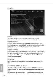
... mode. Easy Driver Installer For users that installs the LAN driver to your system via an USB storage device, then downloads and installs the other required drivers automatically. 4.5 Tool RGB LED ASRock RGB LED allows you to copy the RAID driver from our support CD, Easy Driver Installer...and run Instant Flash to update your UEFI. After copying the drivers please change the SATA mode to your USB storage device. Internet Flash - DHCP (Auto IP), Auto ASRock Internet Flash downloads and updates the latest UEFI firmware version from our servers for you can start installing the ...
... mode. Easy Driver Installer For users that installs the LAN driver to your system via an USB storage device, then downloads and installs the other required drivers automatically. 4.5 Tool RGB LED ASRock RGB LED allows you to copy the RAID driver from our support CD, Easy Driver Installer...and run Instant Flash to update your UEFI. After copying the drivers please change the SATA mode to your USB storage device. Internet Flash - DHCP (Auto IP), Auto ASRock Internet Flash downloads and updates the latest UEFI firmware version from our servers for you can start installing the ...

User Manual
Page 76
... up by the onboard LAN. Full Screen Logo Enable to display the boot logo or disable to wait for you may not boot from an USB storage device. B450 Pro4 4.8 Boot Screen This section displays the available devices on your computer's boot time.
... up by the onboard LAN. Full Screen Logo Enable to display the boot logo or disable to wait for you may not boot from an USB storage device. B450 Pro4 4.8 Boot Screen This section displays the available devices on your computer's boot time.

Quick Installation Guide
Page 3
... 27 Top: LINE IN Center: FRONT Bottom: MIC IN USB 3.1 Gen2 T: USB31_TA_1 B: USB31_TC_1 USB 3.1 Gen1 T: USB1 B: USB2 USB 3.1 Gen1 T: USB3 B: USB4 CHA_FAN1/WP RJ-45 LAN BIOS ROM PCIE1 PCIE2 M2_1 1 Ultra M.2 PCIe Gen3 x4 USB3_5_6 Super I/O PCIE3 PCIE5 CMOS Battery PCIE4 B450 Pro4 AMD Promontory B450 M2_2 HD_AUDIO1 1 PCIE6 TPMS1 1 RGB_LED1 1 COM1 1 RoHS USB_1_2 1 SPK_PLED1...
... 27 Top: LINE IN Center: FRONT Bottom: MIC IN USB 3.1 Gen2 T: USB31_TA_1 B: USB31_TC_1 USB 3.1 Gen1 T: USB1 B: USB2 USB 3.1 Gen1 T: USB3 B: USB4 CHA_FAN1/WP RJ-45 LAN BIOS ROM PCIE1 PCIE2 M2_1 1 Ultra M.2 PCIe Gen3 x4 USB3_5_6 Super I/O PCIE3 PCIE5 CMOS Battery PCIE4 B450 Pro4 AMD Promontory B450 M2_2 HD_AUDIO1 1 PCIE6 TPMS1 1 RGB_LED1 1 COM1 1 RoHS USB_1_2 1 SPK_PLED1...
Quick Installation Guide
Page 4
...) 3 AMD Fan LED Header (AMD_FAN_LED1) 4 CPU Fan / Waterpump Fan Connector (CPU_FAN2/WP) 5 CPU Fan Connector (CPU_FAN1) 6 ATX Power Connector (ATXPWR1) 7 USB 3.1 Gen1 Header (USB3_5_6) 8 SATA3 Connector (SATA3_2) 9 SATA3 Connector (SATA3_1) 10 2 x 288-pin DDR4 DIMM Slots (DDR4_A2, DDR4_B2) 11 SATA3 Connector (SATA3_A1...WP) 18 Chassis Fan / Waterpump Fan Connector (CHA_FAN2/WP) 19 Clear CMOS Jumper (CLRCMOS2) 20 Addressable LED Header (ADDR_LED1) 21 USB 2.0 Header (USB_3_4) 22 USB 2.0 Header (USB_1_2) 23 COM Port Header (COM1) 24 RGB LED Header (RGB_LED1) 25 TPM Header (TPMS1) 26 Front Panel...
...) 3 AMD Fan LED Header (AMD_FAN_LED1) 4 CPU Fan / Waterpump Fan Connector (CPU_FAN2/WP) 5 CPU Fan Connector (CPU_FAN1) 6 ATX Power Connector (ATXPWR1) 7 USB 3.1 Gen1 Header (USB3_5_6) 8 SATA3 Connector (SATA3_2) 9 SATA3 Connector (SATA3_1) 10 2 x 288-pin DDR4 DIMM Slots (DDR4_A2, DDR4_B2) 11 SATA3 Connector (SATA3_A1...WP) 18 Chassis Fan / Waterpump Fan Connector (CHA_FAN2/WP) 19 Clear CMOS Jumper (CLRCMOS2) 20 Addressable LED Header (ADDR_LED1) 21 USB 2.0 Header (USB_3_4) 22 USB 2.0 Header (USB_1_2) 23 COM Port Header (COM1) 24 RGB LED Header (RGB_LED1) 25 TPM Header (TPMS1) 26 Front Panel...

Quick Installation Guide
Page 5
...2 DisplayPort 1.2 3 LAN RJ-45 Port* 4 Line In (Light Blue)** 5 Front Speaker (Lime)** 6 Microphone (Pink)** 7 USB 3.1 Gen1 Ports (USB3_34) No. Please refer to the table below for the LAN port LED indications. ACT/LINK LED SPEED LED ...Description 10Mbps connection 100Mbps connection 1Gbps connection 3 English Description 8 USB 3.1 Gen1 Ports (USB3_12) 9 USB 3.1 Gen2 Type-A Port (USB31_TA_1) 10 USB 3.1 Gen2 Type-C Port (USB31_TC_1) 11 HDMI Port 12 D-Sub Port 13 PS/2 Mouse/Keyboard Port * There are two LEDs on each LAN port. I/O Panel 1 2 B450 Pro4 4 3 5 13 12 11 9 8 7 6 ...
...2 DisplayPort 1.2 3 LAN RJ-45 Port* 4 Line In (Light Blue)** 5 Front Speaker (Lime)** 6 Microphone (Pink)** 7 USB 3.1 Gen1 Ports (USB3_34) No. Please refer to the table below for the LAN port LED indications. ACT/LINK LED SPEED LED ...Description 10Mbps connection 100Mbps connection 1Gbps connection 3 English Description 8 USB 3.1 Gen1 Ports (USB3_12) 9 USB 3.1 Gen2 Type-A Port (USB31_TA_1) 10 USB 3.1 Gen2 Type-C Port (USB31_TC_1) 11 HDMI Port 12 D-Sub Port 13 PS/2 Mouse/Keyboard Port * There are two LEDs on each LAN port. I/O Panel 1 2 B450 Pro4 4 3 5 13 12 11 9 8 7 6 ...

Quick Installation Guide
Page 10
If either one of them is required to use , the others will be disabled. English 8 tection) • 1 x USB 3.1 Gen2 Type-C Port (10 Gb/s) (Supports ESD Pro- tection) • 4 x USB 3.1 Gen1 Ports (Supports ESD Protection) • 1 x RJ-45 LAN Port with Content Protection (Realtek ALC892 Audio Codec) * To configure ...3az • Supports PXE Rear Panel I/O • 1 x PS/2 Mouse/Keyboard Port • 1 x D-Sub Port • 1 x HDMI Port • 1 x DisplayPort 1.2 • 2 x USB 2.0 Ports (Supports ESD Protection) • 1 x USB 3.1 Gen2 Type-A Port (10 Gb/s) (Supports ESD Pro-
If either one of them is required to use , the others will be disabled. English 8 tection) • 1 x USB 3.1 Gen2 Type-C Port (10 Gb/s) (Supports ESD Pro- tection) • 4 x USB 3.1 Gen1 Ports (Supports ESD Protection) • 1 x RJ-45 LAN Port with Content Protection (Realtek ALC892 Audio Codec) * To configure ...3az • Supports PXE Rear Panel I/O • 1 x PS/2 Mouse/Keyboard Port • 1 x D-Sub Port • 1 x HDMI Port • 1 x DisplayPort 1.2 • 2 x USB 2.0 Ports (Supports ESD Protection) • 1 x USB 3.1 Gen2 Type-A Port (10 Gb/s) (Supports ESD Pro-
Quick Installation Guide
Page 12
... ErP/EuP ready (ErP/EuP ready power supply is required) * For detailed product information, please visit our website: http://www.asrock.com Please realize that there is a certain risk involved with multilingual GUI support • Supports "Plug and Play" • ...Auto adjust chassis fan speed by overclocking. • 1 x Front Panel Audio Connector • 2 x USB 2.0 Headers (Support 4 USB 2.0 ports) (Supports ESD Protection) • 1 x USB 3.1 Gen1 Header (Supports 2 USB 3.1 Gen1 ports) (Supports ESD Protection) BIOS Feature • AMI UEFI Legal BIOS with overclocking, including...
... ErP/EuP ready (ErP/EuP ready power supply is required) * For detailed product information, please visit our website: http://www.asrock.com Please realize that there is a certain risk involved with multilingual GUI support • Supports "Plug and Play" • ...Auto adjust chassis fan speed by overclocking. • 1 x Front Panel Audio Connector • 2 x USB 2.0 Headers (Support 4 USB 2.0 ports) (Supports ESD Protection) • 1 x USB 3.1 Gen1 Header (Supports 2 USB 3.1 Gen1 ports) (Supports ESD Protection) BIOS Feature • AMI UEFI Legal BIOS with overclocking, including...

Quick Installation Guide
Page 24
Please refer to page 32 for reference only. If you select AMD_FAN_LED1, please install ASRock utility "ASRock Polychrome LED". If you select USB connector, please install AMD utility "SR3 Settings Software". *The diagram shown here are for the orientation of AMD Fan LED Header (AMD_FAN_LED1). 22 English 6 CPU_FAN1 +12V AMD_FAN_LED1 or 7 CPU_FAN1 AMD_FAN_LED1 USB_5 Please note that only one cable should be used at a time in this step.
Please refer to page 32 for reference only. If you select AMD_FAN_LED1, please install ASRock utility "ASRock Polychrome LED". If you select USB connector, please install AMD utility "SR3 Settings Software". *The diagram shown here are for the orientation of AMD Fan LED Header (AMD_FAN_LED1). 22 English 6 CPU_FAN1 +12V AMD_FAN_LED1 or 7 CPU_FAN1 AMD_FAN_LED1 USB_5 Please note that only one cable should be used at a time in this step.


