
User Manual
Page 2
...battery in California, USA, please follow the related regulations in advance. This device complies with Part 15 of ASRock Inc. ASRock assumes no event shall ASRock, its directors, officers, employees, or agents be liable for any indirect, special, incidental, or consequential ...a particular purpose. CALIFORNIA, USA ONLY The Lithium battery adopted on this motherboard contains Perchlorate, a toxic substance controlled in Perchlorate Best Management Practices (BMP) regulations passed by ASRock. Disclaimer: Specifications and information contained in this manual are used only for ...
...battery in California, USA, please follow the related regulations in advance. This device complies with Part 15 of ASRock Inc. ASRock assumes no event shall ASRock, its directors, officers, employees, or agents be liable for any indirect, special, incidental, or consequential ...a particular purpose. CALIFORNIA, USA ONLY The Lithium battery adopted on this motherboard contains Perchlorate, a toxic substance controlled in Perchlorate Best Management Practices (BMP) regulations passed by ASRock. Disclaimer: Specifications and information contained in this manual are used only for ...

User Manual
Page 3
... (SATA) / Serial ATAII (SATAII) Hard Disks Installation 35 2.14 Hot Plug and Hot Swap Functions for Windows® VistaTM Premium 2007 and Basic Logo 9 1.4 Motherboard Layout 10 1.5 ASRock 8CH_eSATAII I/O 11 2 . Introduction 5 1.1 Package Contents 5 1.2 Specifications 6 1.3 Minimum Hardware Requirement Table for SATA / SATAII HDDs and eSATAII Devices 35 2.15 Driver Installation Guide 36 2.16...
... (SATA) / Serial ATAII (SATAII) Hard Disks Installation 35 2.14 Hot Plug and Hot Swap Functions for Windows® VistaTM Premium 2007 and Basic Logo 9 1.4 Motherboard Layout 10 1.5 ASRock 8CH_eSATAII I/O 11 2 . Introduction 5 1.1 Package Contents 5 1.2 Specifications 6 1.3 Minimum Hardware Requirement Table for SATA / SATAII HDDs and eSATAII Devices 35 2.15 Driver Installation Guide 36 2.16...

User Manual
Page 5
... jumpers. 5 In case any modifications of this manual, chapter 1 and 2 contain introduction of the Support CD. ASRock website http://www.asrock.com 1.1 Package Contents 1 x ASRock ALiveXFire-eSATA2 Motherboard (ATX Form Factor: 12.0-in x 8.2-in, 30.5 cm x 20.8 cm) 1 x ASRock ALiveXFire-eSATA2 Quick Installation Guide 1 x ASRock ALiveXFire-eSATA2 Support CD 1 x Ultra ATA 66/100/133 IDE Ribbon Cable (80-conductor) 1 x 3.5-in Floppy Drive...
... jumpers. 5 In case any modifications of this manual, chapter 1 and 2 contain introduction of the Support CD. ASRock website http://www.asrock.com 1.1 Package Contents 1 x ASRock ALiveXFire-eSATA2 Motherboard (ATX Form Factor: 12.0-in x 8.2-in, 30.5 cm x 20.8 cm) 1 x ASRock ALiveXFire-eSATA2 Quick Installation Guide 1 x ASRock ALiveXFire-eSATA2 Support CD 1 x Ultra ATA 66/100/133 IDE Ribbon Cable (80-conductor) 1 x 3.5-in Floppy Drive...

User Manual
Page 8
... in the BIOS setup, the memory performance will automatically shutdown. In CrossFireTM mode, the two ATITM graphics cards you enable this motherboard offers stepless control, it is not recommended to read "Untied Overclocking Technology" on page 42 for ATITM CrossFireTM without setting up to...the AM2 CPU you adopt 4GB or more memory, the actual memory size may cause the instability of your system. 7. This motherboard supports ASRock AM2 Boost overclocking technology. WARNING Please realize that PCIE Switch card is installed on PCIE2/PCIE SWITCH slot. Although this function in...
... in the BIOS setup, the memory performance will automatically shutdown. In CrossFireTM mode, the two ATITM graphics cards you enable this motherboard offers stepless control, it is not recommended to read "Untied Overclocking Technology" on page 42 for ATITM CrossFireTM without setting up to...the AM2 CPU you adopt 4GB or more memory, the actual memory size may cause the instability of your system. 7. This motherboard supports ASRock AM2 Boost overclocking technology. WARNING Please realize that PCIE Switch card is installed on PCIE2/PCIE SWITCH slot. Although this function in...

User Manual
Page 9
...on page 11 for Windows® VistaTM Premium 2007 and Basic Logo For system integrators and users who purchase this motherboard supports both stereo and mono modes. Before installing SATAII hard disk to submit Windows® VistaTM Premium 2007 and Basic... in order to SATAII connector directly. 11. ASRock website http://www.asrock.com 1.3 Minimum Hardware Requirement Table for proper connection. 10. For audio output, this motherboard supports 2-channel, 4-channel, 6-channel, and 8-channel modes. This motherboard supports eSATAII interface, the external SATAII specification. ...
...on page 11 for Windows® VistaTM Premium 2007 and Basic Logo For system integrators and users who purchase this motherboard supports both stereo and mono modes. Before installing SATAII hard disk to submit Windows® VistaTM Premium 2007 and Basic... in order to SATAII connector directly. 11. ASRock website http://www.asrock.com 1.3 Minimum Hardware Requirement Table for proper connection. 10. For audio output, this motherboard supports 2-channel, 4-channel, 6-channel, and 8-channel modes. This motherboard supports eSATAII interface, the external SATAII specification. ...

User Manual
Page 12
...in the bag that the power is switched off or the power cord is an ATX form factor (12.0-in x 8.2-in, 30.5 cm x 20.8 cm) motherboard. Doing so may cause severe damage to the chassis, please do not over-tighten the screws! To avoid damaging the... of the following precautions before you handle components. 3. Hold components by the edges and do so may damage the motherboard. 12 Installation This is detached from the wall socket before you install motherboard components or change any component, ensure that comes with the component. 5. 2. Also remember to do not touch the ICs...
...in the bag that the power is switched off or the power cord is an ATX form factor (12.0-in x 8.2-in, 30.5 cm x 20.8 cm) motherboard. Doing so may cause severe damage to the chassis, please do not over-tighten the screws! To avoid damaging the... of the following precautions before you handle components. 3. Hold components by the edges and do so may damage the motherboard. 12 Installation This is detached from the wall socket before you install motherboard components or change any component, ensure that comes with the component. 5. 2. Also remember to do not touch the ICs...

User Manual
Page 13
The CPU fits only in place. The lever clicks on the socket while you install the CPU into this motherboard, it firmly on the side tab to indicate that the CPU corner with the golden triangle matches the socket corner with each other. 2.1 CPU Installation ...
The CPU fits only in place. The lever clicks on the socket while you install the CPU into this motherboard, it firmly on the side tab to indicate that the CPU corner with the golden triangle matches the socket corner with each other. 2.1 CPU Installation ...

User Manual
Page 14
If only one memory module or three memory modules are installed in the DDRII DIMM slots on this motherboard and DIMM may refer to the Dual Channel Memory Configuration Table below. You may be activated. Dual Channel Memory Configurations DDRII_1 DDRII_2 DDRII_3...DDRII_1 and DDRII_2), or in the set of memory modules in Dual Channel A (DDRII_1 and DDRII_2; This motherboard also allows you have to activate the Dual Channel Memory Technology. 3. otherwise, this motherboard, it is unable to install identical DDRII DIMM pair in DDRII_1 and DDRII_3, it is not allowed to...
If only one memory module or three memory modules are installed in the DDRII DIMM slots on this motherboard and DIMM may refer to the Dual Channel Memory Configuration Table below. You may be activated. Dual Channel Memory Configurations DDRII_1 DDRII_2 DDRII_3...DDRII_1 and DDRII_2), or in the set of memory modules in Dual Channel A (DDRII_1 and DDRII_2; This motherboard also allows you have to activate the Dual Channel Memory Technology. 3. otherwise, this motherboard, it is unable to install identical DDRII DIMM pair in DDRII_1 and DDRII_3, it is not allowed to...

User Manual
Page 15
... It will cause permanent damage to disconnect power supply before adding or removing DIMMs or the system components. Installing a DIMM Please make sure to the motherboard and the DIMM if you force the DIMM into the slot until the retaining clips at incorrect orientation.
... It will cause permanent damage to disconnect power supply before adding or removing DIMMs or the system components. Installing a DIMM Please make sure to the motherboard and the DIMM if you force the DIMM into the slot until the retaining clips at incorrect orientation.

User Manual
Page 16
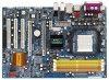
PCIE Slots: PCIE1 slot (PCI Express x1 slot) is installed on this motherboard. In CrossFireTM mode, the two ATITM graphics cards you install should be from PCIE2/PCIE SWITCH slot before you use one PCI Express x16 slot ...
PCIE Slots: PCIE1 slot (PCI Express x1 slot) is installed on this motherboard. In CrossFireTM mode, the two ATITM graphics cards you install should be from PCIE2/PCIE SWITCH slot before you use one PCI Express x16 slot ...

User Manual
Page 17
... bracket facing the slot that the power supply is switched off or the power cord is unplugged. Step 5. Remove the system unit cover (if your motherboard is completely seated on the slot. Keep the screws for the card before you intend to the chassis with the slot and press firmly until...
... bracket facing the slot that the power supply is switched off or the power cord is unplugged. Step 5. Remove the system unit cover (if your motherboard is completely seated on the slot. Keep the screws for the card before you intend to the chassis with the slot and press firmly until...

User Manual
Page 19
...Ready cards if they will not see the performance benefits of CrossFireTM. 2.6 Installing CrossFireTM Graphics Cards This motherboard supports CrossFireTM feature. CrossFireTM technology offers the most advantageous means available of different operating modes with Service Pack... which require different methods to benefit from the CrossFireTM multi-GPU platform. 2. w A complete CrossFireTM system requires a CrossFireTM Ready motherboard, a CrossFireTM Edition graphics card and a compatible standard Radeon S (CrossFireTM Ready) graphics card from ATITM or C any 3D application...
...Ready cards if they will not see the performance benefits of CrossFireTM. 2.6 Installing CrossFireTM Graphics Cards This motherboard supports CrossFireTM feature. CrossFireTM technology offers the most advantageous means available of different operating modes with Service Pack... which require different methods to benefit from the CrossFireTM multi-GPU platform. 2. w A complete CrossFireTM system requires a CrossFireTM Ready motherboard, a CrossFireTM Edition graphics card and a compatible standard Radeon S (CrossFireTM Ready) graphics card from ATITM or C any 3D application...

User Manual
Page 20
... are allowed to install two CrossFireTM Edition graphics cards to both slots, or you install two standard Radeon (CrossFireTM Ready) graphics cards to this motherboard, please skip this motherboard. Besides, please connect the monitor cable to PCIE3 slot. For the proper installation procedures, please refer to the system power supply. You are...
... are allowed to install two CrossFireTM Edition graphics cards to both slots, or you install two standard Radeon (CrossFireTM Ready) graphics cards to this motherboard, please skip this motherboard. Besides, please connect the monitor cable to PCIE3 slot. For the proper installation procedures, please refer to the system power supply. You are...

User Manual
Page 21
... utility to uninstall any VGA driver installed in your computer and boot into OS. If you install two CrossFireTM Edition graphics cards to this motherboard, please connect one of the CrossFireTM Edition graphics cards to PCIE3 slot, and the other end to DVI of another CrossFireTM Edition graphics card...slot. Remove the ATITM driver if you install one CrossFireTM Edition graphics card and one compatible standard Radeon (CrossFireTM Ready) graphics card to this motherboard, please connect one end of DVI-DMS cable to the monitor, another end to DMS of one end of DVI-DMS cable to the ...
... utility to uninstall any VGA driver installed in your computer and boot into OS. If you install two CrossFireTM Edition graphics cards to this motherboard, please connect one of the CrossFireTM Edition graphics cards to PCIE3 slot, and the other end to DVI of another CrossFireTM Edition graphics card...slot. Remove the ATITM driver if you install one CrossFireTM Edition graphics card and one compatible standard Radeon (CrossFireTM Ready) graphics card to this motherboard, please connect one end of DVI-DMS cable to the monitor, another end to DMS of one end of DVI-DMS cable to the ...

User Manual
Page 23
... benefit of CrossFireTM feature. However, although you install one Radeon CrossFireTM Edition graphics card and one compatible standard Radeon (CrossFireTM Ready) graphics card to this motherboard but not two Radeon CrossFireTM Edition graphics cards, please as well follow the above steps. Your computer will automatically reboot. Step 12. n e E 23 You can...
... benefit of CrossFireTM feature. However, although you install one Radeon CrossFireTM Edition graphics card and one compatible standard Radeon (CrossFireTM Ready) graphics card to this motherboard but not two Radeon CrossFireTM Edition graphics cards, please as well follow the above steps. Your computer will automatically reboot. Step 12. n e E 23 You can...

User Manual
Page 24
... 2_3 Short pin2, pin3 to default setup, please turn off the computer and unplug the power cord from the power supply. 2.7 Surround Display Feature This motherboard supports Surround Display upgrade.
... 2_3 Short pin2, pin3 to default setup, please turn off the computer and unplug the power cord from the power supply. 2.7 Surround Display Feature This motherboard supports Surround Display upgrade.

User Manual
Page 25
...see p.10, No. 16) (SATAII_RED (PORT 1): see p.10, No. 15) (SATAII_ORANGE (PORT 2): see p.10 No. 9) PIN1 IDE1 connect the blue end to the motherboard connect the black end to the IDE devices 80-conductor ATA 66/100/133 cable Note: Please refer to support eSATAII devices. SATAII_RED (PORT 1) and...current SATAII interface allows up to Pin1 Note: Make sure the red-striped side of the cable is plugged into Pin1 side of the motherboard! • Floppy Connector (33-pin FLOPPY1) (see p.10, No. 37) eSATAII_TOP eSATAII_BOTTOM These two eSATAII connectors support SATA data cables ...
...see p.10, No. 16) (SATAII_RED (PORT 1): see p.10, No. 15) (SATAII_ORANGE (PORT 2): see p.10 No. 9) PIN1 IDE1 connect the blue end to the motherboard connect the black end to the IDE devices 80-conductor ATA 66/100/133 cable Note: Please refer to support eSATAII devices. SATAII_RED (PORT 1) and...current SATAII interface allows up to Pin1 Note: Make sure the red-striped side of the cable is plugged into Pin1 side of the motherboard! • Floppy Connector (33-pin FLOPPY1) (see p.10, No. 37) eSATAII_TOP eSATAII_BOTTOM These two eSATAII connectors support SATA data cables ...

User Manual
Page 26
... P-9 P+9 GND DUMMY 1 GND P+8 P-8 USB_PWR USB_PWR P-7 P+7 GND DUMMY 1 GND P+6 P-6 USB_PWR Besides two default USB 2.0 ports on the I/O panel, there are four USB 2.0 headers on the motherboard. Serial ATA (SATA) Data Cable (Optional) Either end of the SATA data cable can also use the SATA data cable to connect SATAII connectors and...(SATA) Power Cable (Optional) connect to the SATA HDD power connector connect to the SATA / SATAII hard disk or the SATAII connector on this motherboard. You can be connected to the power supply Please connect the black end of the power supply.
... P-9 P+9 GND DUMMY 1 GND P+8 P-8 USB_PWR USB_PWR P-7 P+7 GND DUMMY 1 GND P+6 P-6 USB_PWR Besides two default USB 2.0 ports on the I/O panel, there are four USB 2.0 headers on the motherboard. Serial ATA (SATA) Data Cable (Optional) Either end of the SATA data cable can also use the SATA data cable to connect SATAII connectors and...(SATA) Power Cable (Optional) connect to the SATA HDD power connector connect to the SATA / SATAII hard disk or the SATAII connector on this motherboard. You can be connected to the power supply Please connect the black end of the power supply.

User Manual
Page 28
... Fan Connector (4-pin CPU_FAN1) (see p.10 No. 3) FAN_SPEED_CONTROL 4 CPU_FAN_SPEED 3 +12V 2 GND 1 Please connect the CPU fan cable to this motherboard provides 4-Pin CPU fan (Quiet Fan) support, the 3-Pin CPU fan still can work successfully even without the fan speed control function. Though this... Header (4-pin SPEAKER 1) (see p.10 No. 24) Chassis Fan Connector (3-pin CHA_FAN1) (see p.10 No. 4) Please connect an ATX power supply to this motherboard at the same time. Failing to the CPU fan connector on this header. Please connect the chassis speaker to this...
... Fan Connector (4-pin CPU_FAN1) (see p.10 No. 3) FAN_SPEED_CONTROL 4 CPU_FAN_SPEED 3 +12V 2 GND 1 Please connect the CPU fan cable to this motherboard provides 4-Pin CPU fan (Quiet Fan) support, the 3-Pin CPU fan still can work successfully even without the fan speed control function. Though this... Header (4-pin SPEAKER 1) (see p.10 No. 24) Chassis Fan Connector (3-pin CHA_FAN1) (see p.10 No. 4) Please connect an ATX power supply to this motherboard at the same time. Failing to the CPU fan connector on this header. Please connect the chassis speaker to this...

User Manual
Page 29
... (USB2_3, USB4_5, USB6_7 or USB8_9) and fasten the USB bracket to connect HDMI Digital TV/ projector/LCD devices. A. Please connect the blue connector on the motherboard. black end +5V SPDIFOUT GND blue black B. white end (3-pin) SPDIFOUT GND blue black USB Bracket This USB bracket can support 2 additional USB 2.0 ports besides...
... (USB2_3, USB4_5, USB6_7 or USB8_9) and fasten the USB bracket to connect HDMI Digital TV/ projector/LCD devices. A. Please connect the blue connector on the motherboard. black end +5V SPDIFOUT GND blue black B. white end (3-pin) SPDIFOUT GND blue black USB Bracket This USB bracket can support 2 additional USB 2.0 ports besides...

