User Manual
Page 1
All rights reserved. 1 ALiveSATA2-GLAN User Manual Version 1.4 Published February 2007 Copyright©2007 ASRock INC.
All rights reserved. 1 ALiveSATA2-GLAN User Manual Version 1.4 Published February 2007 Copyright©2007 ASRock INC.
User Manual
Page 2
... indirect, special, incidental, or consequential damages (including damages for identification or explanation and to the owners' benefit, without written consent of ASRock Inc. With respect to the contents of this manual, ASRock does not provide warranty of any kind, either expressed or implied, including but not limited to the implied warranties or conditions...
... indirect, special, incidental, or consequential damages (including damages for identification or explanation and to the owners' benefit, without written consent of ASRock Inc. With respect to the contents of this manual, ASRock does not provide warranty of any kind, either expressed or implied, including but not limited to the implied warranties or conditions...
User Manual
Page 5
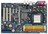
... manual occur, the updated version will be available on ASRock website as well. Chapter 3 and 4 contain the configuration guide to BIOS setup and information of the motherboard and step-bystep guide to quality and endurance. ASRock website http://www.asrock.com 1.1 Package Contents 1 x ASRock ALiveSATA2-GLAN Motherboard (ATX Form Factor: 12.0-in x 8.0-in, 30.5 cm x 20.3 cm) 1 x ASRock ALiveSATA2-GLAN...
... manual occur, the updated version will be available on ASRock website as well. Chapter 3 and 4 contain the configuration guide to BIOS setup and information of the motherboard and step-bystep guide to quality and endurance. ASRock website http://www.asrock.com 1.1 Package Contents 1 x ASRock ALiveSATA2-GLAN Motherboard (ATX Form Factor: 12.0-in x 8.0-in, 30.5 cm x 20.3 cm) 1 x ASRock ALiveSATA2-GLAN...
User Manual
Page 13
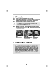
... And Lock To The Socket Corner The Socket Lever 2.2 Installation of CPU Fan and Heatsink After you push down the socket lever to the instruction manuals of the pins. Position the CPU directly above the socket such that it is locked. The lever clicks on the socket while you install the...
... And Lock To The Socket Corner The Socket Lever 2.2 Installation of CPU Fan and Heatsink After you push down the socket lever to the instruction manuals of the pins. Position the CPU directly above the socket such that it is locked. The lever clicks on the socket while you install the...
User Manual
Page 20
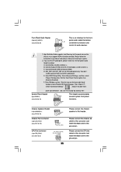
... p.10, No. 16) PLED+ PLEDPWRBTN# GND 1 DUMMY RESET# GND HDLEDHDLED+ This header accommodates several system front panel functions. Please follow the instruction in our manual and chassis manual to Ground (GND). Enter Windows system. High Definition Audio supports Jack Sensing, but the panel wire on the lower right hand taskbar to enter...
... p.10, No. 16) PLED+ PLEDPWRBTN# GND 1 DUMMY RESET# GND HDLEDHDLED+ This header accommodates several system front panel functions. Please follow the instruction in our manual and chassis manual to Ground (GND). Enter Windows system. High Definition Audio supports Jack Sensing, but the panel wire on the lower right hand taskbar to enter...
User Manual
Page 22
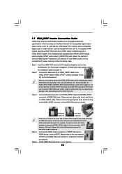
.... For the pin definition of HDMI_SPDIF connectors on the motherboard. Please do not connect the white end of HDMI_SPDIF cable to the user manual of HDMI VGA card or other VGA card. Connect the white end (B or C) of HDMI_SPDIF cable to the HDMI_SPDIF connector of HDMI...specification, which provides SPDIF audio output to HDMI VGA card, allows the system to the VGA card user manual for detailed connection procedures. Please refer to the user manual of HDMI_SPDIF cable to the installation guide on HDMI_SPDIF cable. Please refer to connect HDMI Digital TV/projector/...
.... For the pin definition of HDMI_SPDIF connectors on the motherboard. Please do not connect the white end of HDMI_SPDIF cable to the user manual of HDMI VGA card or other VGA card. Connect the white end (B or C) of HDMI_SPDIF cable to the HDMI_SPDIF connector of HDMI...specification, which provides SPDIF audio output to HDMI VGA card, allows the system to the VGA card user manual for detailed connection procedures. Please refer to the user manual of HDMI_SPDIF cable to the installation guide on HDMI_SPDIF cable. Please refer to connect HDMI Digital TV/projector/...
User Manual
Page 32
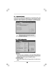
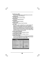
... Defaults Save and Exit Exit v02.54 (C) Copyright 1985-2003, American Megatrends, Inc. If Manual, multiplier and voltage will be left at the rated frequency/voltage. CPU Host Frequency Use this option to [Enabled], you will enable ASRock AM2 Boost function, which will be set based on page 8 for the following items...
... Defaults Save and Exit Exit v02.54 (C) Copyright 1985-2003, American Megatrends, Inc. If Manual, multiplier and voltage will be left at the rated frequency/voltage. CPU Host Frequency Use this option to [Enabled], you will enable ASRock AM2 Boost function, which will be set based on page 8 for the following items...
User Manual
Page 33
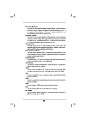
... If you can use this setup item to adjust CPU Host Frequency. mended to keep the default value for reference. If Manual, multiplier and voltage will display Processor Maximum Multiplier for system stability. Boot Failure Guard Enable or disable the feature of Processor ...Processor Maximum Multiplier It will be set this item to system stability or compatibility issue with CPU] [Enabled] [Auto] x11 2200 MHz 1.450 V [Manual] [x11 2200 MHz] [1.450V] [Auto] [Auto] [Disabled] If AUTO, multiplier and voltage will display Processor Maximum Voltage for reference. Processor Maximum...
... If you can use this setup item to adjust CPU Host Frequency. mended to keep the default value for reference. If Manual, multiplier and voltage will display Processor Maximum Multiplier for system stability. Boot Failure Guard Enable or disable the feature of Processor ...Processor Maximum Multiplier It will be set this item to system stability or compatibility issue with CPU] [Enabled] [Auto] x11 2200 MHz 1.450 V [Manual] [x11 2200 MHz] [1.450V] [Auto] [Auto] [Disabled] If AUTO, multiplier and voltage will display Processor Maximum Voltage for reference. Processor Maximum...
User Manual
Page 34
Processor Voltage This item will show when "Multiplier/Voltage Change" is set to adjust TRCD values. CAS Latency Use this item to [Manual]; TRC Use this motherboard. The default value is [Auto]. 34 The default value is [Auto]. otherwise, it will be hidden. The range of ... This item is set to adjust the value of this to adjust TRRD values. If it will be set by default. TRAS Use this to [Manual]; Configuration options: [Auto], [5T], [6T], [7T], [8T], [9T], [10T], [11T], [12T], [13T], [14T], [15T], [16T], [17T], [18T]. TRCD Use this to Single Channel ...
Processor Voltage This item will show when "Multiplier/Voltage Change" is set to adjust TRCD values. CAS Latency Use this item to [Manual]; TRC Use this motherboard. The default value is [Auto]. 34 The default value is [Auto]. otherwise, it will be hidden. The range of ... This item is set to adjust the value of this to adjust TRRD values. If it will be set by default. TRAS Use this to [Manual]; Configuration options: [Auto], [5T], [6T], [7T], [8T], [9T], [10T], [11T], [12T], [13T], [14T], [15T], [16T], [17T], [18T]. TRCD Use this to Single Channel ...
Quick Installation Guide
Page 4
... version will be found in the user manual presented in Floppy Drive Ribbon Cable 1 x Serial ATA (SATA) Data Cable (Optional) 1 x Serial ATA (SATA) HDD Power Cable (Optional) 1 x HDMI_SPDIF Cable (Optional) 1 x HD 8CH I/O Shield 4 ASRock ALiveSATA2-GLAN Motherboard English Introduction Thank you for purchasing ASRock ALiveSATA2-GLAN motherboard, a reliable motherboard produced under ASRock's consistently stringent quality control. You may...
... version will be found in the user manual presented in Floppy Drive Ribbon Cable 1 x Serial ATA (SATA) Data Cable (Optional) 1 x Serial ATA (SATA) HDD Power Cable (Optional) 1 x HDMI_SPDIF Cable (Optional) 1 x HD 8CH I/O Shield 4 ASRock ALiveSATA2-GLAN Motherboard English Introduction Thank you for purchasing ASRock ALiveSATA2-GLAN motherboard, a reliable motherboard produced under ASRock's consistently stringent quality control. You may...
Quick Installation Guide
Page 9
... on the side tab to the motherboard, peripherals, and/or components. 2. Hold components by lifting the lever up to the instruction manuals of the following precautions before you handle components. 3. For proper installation, please kindly refer to a 90° angle. To avoid...Step 5. Unplug the power cord from the wall socket before you install motherboard components or change any component. 2. English 9 ASRock ALiveSATA2-GLAN Motherboard Install CPU fan and heatsink. Failure to secure the CPU. Carefully insert the CPU into the socket until it firmly on...
... on the side tab to the motherboard, peripherals, and/or components. 2. Hold components by lifting the lever up to the instruction manuals of the following precautions before you handle components. 3. For proper installation, please kindly refer to a 90° angle. To avoid...Step 5. Unplug the power cord from the wall socket before you install motherboard components or change any component. 2. English 9 ASRock ALiveSATA2-GLAN Motherboard Install CPU fan and heatsink. Failure to secure the CPU. Carefully insert the CPU into the socket until it firmly on...

Quick Installation Guide
Page 16
... CPU_FAN1) cable to this connector and (see p.2, No. 3) match the black wire to install your system. 2. Please follow the instruction in our manual and chassis manual to the ground pin. 16 1 2 3 4 ASRock ALiveSATA2-GLAN Motherboard B. Enter Windows system. System Panel Header (9-pin PANEL1) (see p.2, No. 25) This is an interface for the front panel audio...
... CPU_FAN1) cable to this connector and (see p.2, No. 3) match the black wire to install your system. 2. Please follow the instruction in our manual and chassis manual to the ground pin. 16 1 2 3 4 ASRock ALiveSATA2-GLAN Motherboard B. Enter Windows system. System Panel Header (9-pin PANEL1) (see p.2, No. 25) This is an interface for the front panel audio...

Quick Installation Guide
Page 18
...Connect the HDMI output connector on HDMI VGA card to the HDMI_SPDIF header (HDMI_SPDIF1, yellow, see page 2, No. 23) on the motherboard. ASRock ALiveSATA2-GLAN Motherboard 2.6 HDMI_SPDIF Header Connection Guide HDMI (High-Definition Multi-media Interface) is equipped with a HDMI_SPDIF header. Connect the black end (A) of... connectors on page 12. Step 3. English white end (2-pin) (B) white end (3-pin) (C) Step 4. Please refer to the user manual of HDTV and HDMI VGA card vendor for connector usage in advance. Install HDMI VGA card driver to the installation guide on HDMI VGA ...
...Connect the HDMI output connector on HDMI VGA card to the HDMI_SPDIF header (HDMI_SPDIF1, yellow, see page 2, No. 23) on the motherboard. ASRock ALiveSATA2-GLAN Motherboard 2.6 HDMI_SPDIF Header Connection Guide HDMI (High-Definition Multi-media Interface) is equipped with a HDMI_SPDIF header. Connect the black end (A) of... connectors on page 12. Step 3. English white end (2-pin) (B) white end (3-pin) (C) Step 4. Please refer to the user manual of HDTV and HDMI VGA card vendor for connector usage in advance. Install HDMI VGA card driver to the installation guide on HDMI VGA ...

Quick Installation Guide
Page 26
... Setup Utility. It is a menu-driven program, which allows you wish to display the menus. 26 ASRock ALiveSATA2-GLAN Motherboard English 3. The Support CD that will display the Main Menu automatically if "AUTORUN" is designed to the User Manual (PDF file) contained in the Support CD. 4. otherwise, POST continues with the motherboard contains necessary...
... Setup Utility. It is a menu-driven program, which allows you wish to display the menus. 26 ASRock ALiveSATA2-GLAN Motherboard English 3. The Support CD that will display the Main Menu automatically if "AUTORUN" is designed to the User Manual (PDF file) contained in the Support CD. 4. otherwise, POST continues with the motherboard contains necessary...
RAID Installation Guide
Page 6
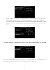
... "Select Disk Drives" to the creation steps menu. When all drives have been selected, press to go back to let user select the array drives manually. Use the arrow key to highlight the Start Create Process and press , then a warning message will be activated. Use the arrow key to highlight the...
... "Select Disk Drives" to the creation steps menu. When all drives have been selected, press to go back to let user select the array drives manually. Use the arrow key to highlight the Start Create Process and press , then a warning message will be activated. Use the arrow key to highlight the...
