User Manual
Page 2
... or fitness for a particular purpose. ASRock assumes no event shall ASRock, its directors, officers, employees, or agents be constructed as a commitment by the California Legislature. With respect to the contents of this motherboard contains Perchlorate, a toxic substance controlled ...in Perchlorate Best Management Practices (BMP) regulations passed by ASRock. "Perchlorate Material-special handling may appear in this manual. When you ...
... or fitness for a particular purpose. ASRock assumes no event shall ASRock, its directors, officers, employees, or agents be constructed as a commitment by the California Legislature. With respect to the contents of this motherboard contains Perchlorate, a toxic substance controlled ...in Perchlorate Best Management Practices (BMP) regulations passed by ASRock. "Perchlorate Material-special handling may appear in this manual. When you ...

User Manual
Page 3
... ATA (SATA) / Serial ATAII (SATAII) Hard Disks Installation 24 2.10 Hot Plug and Hot Swap Functions for Windows® VistaTM Premium 2007 and Basic Logo 9 1.4 Motherboard Layout 10 1.5 HD 8CH I/O Panel 11 2 . Introduction 5 1.1 Package Contents 5 1.2 Specifications 6 1.3 Minimum Hardware Requirement Table for SATA / SATAII HDDs .... 24 2.11 Driver Installation Guide 25 2.12...
... ATA (SATA) / Serial ATAII (SATAII) Hard Disks Installation 24 2.10 Hot Plug and Hot Swap Functions for Windows® VistaTM Premium 2007 and Basic Logo 9 1.4 Motherboard Layout 10 1.5 HD 8CH I/O Panel 11 2 . Introduction 5 1.1 Package Contents 5 1.2 Specifications 6 1.3 Minimum Hardware Requirement Table for SATA / SATAII HDDs .... 24 2.11 Driver Installation Guide 25 2.12...
User Manual
Page 5
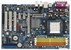
... latest VGA cards and CPU support lists on ASRock website without notice. Introduction Thank you for purchasing ASRock ALiveSATA2-GLAN motherboard, a reliable motherboard produced under ASRock's consistently stringent quality control. ASRock website http://www.asrock.com 1.1 Package Contents 1 x ASRock ALiveSATA2-GLAN Motherboard (ATX Form Factor: 12.0-in x 8.0-in, 30.5 cm x 20.3 cm) 1 x ASRock ALiveSATA2-GLAN Quick Installation Guide 1 x ASRock ALiveSATA2-GLAN Support CD 1 x Ultra ATA 66/100/133 IDE...
... latest VGA cards and CPU support lists on ASRock website without notice. Introduction Thank you for purchasing ASRock ALiveSATA2-GLAN motherboard, a reliable motherboard produced under ASRock's consistently stringent quality control. ASRock website http://www.asrock.com 1.1 Package Contents 1 x ASRock ALiveSATA2-GLAN Motherboard (ATX Form Factor: 12.0-in x 8.0-in, 30.5 cm x 20.3 cm) 1 x ASRock ALiveSATA2-GLAN Quick Installation Guide 1 x ASRock ALiveSATA2-GLAN Support CD 1 x Ultra ATA 66/100/133 IDE...
User Manual
Page 8
...Boost function is detected, the system will automatically shutdown. Although this function in the future. Before you adopt. This motherboard supports ASRock AM2 Boost overclocking technology. Power Management for USB 2.0 works fine under Windows® XP and Windows® VistaTM. ... not guarantee the system stability for proper installation. 3. ASRock website http://www.asrock.com 8 Before you install the PC system. 6. This motherboard supports Dual Channel Memory Technology. If you enable this motherboard offers stepless control, it may not be less than ...
...Boost function is detected, the system will automatically shutdown. Although this function in the future. Before you adopt. This motherboard supports ASRock AM2 Boost overclocking technology. Power Management for USB 2.0 works fine under Windows® XP and Windows® VistaTM. ... not guarantee the system stability for proper installation. 3. ASRock website http://www.asrock.com 8 Before you install the PC system. 6. This motherboard supports Dual Channel Memory Technology. If you enable this motherboard offers stepless control, it may not be less than ...

User Manual
Page 9
1.3 Minimum Hardware Requirement Table for Windows® VistaTM Premium 2007 and Basic Logo For system integrators and users who purchase this motherboard and plan to qualify for minimum hardware requirements. CPU Memory VGA Sempron 2800+ 1GB system memory DX9.0 with WDDM Driver with 128bit VGA memory (Premium) ...
1.3 Minimum Hardware Requirement Table for Windows® VistaTM Premium 2007 and Basic Logo For system integrators and users who purchase this motherboard and plan to qualify for minimum hardware requirements. CPU Memory VGA Sempron 2800+ 1GB system memory DX9.0 with WDDM Driver with 128bit VGA memory (Premium) ...
User Manual
Page 12
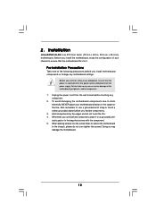
Installation ALiveSATA2-GLAN is detached from the wall socket before you handle components. 3. Hold components by the edges and do not over-tighten the screws! When placing screws into it on the carpet or the like. Pre-installation Precautions Take note of your motherboard directly on a grounded antistatic pad... off or the power cord is an ATX form factor (12.0-in x 8.0-in the bag that the motherboard fits into the screw holes to secure the motherboard to static electricity, NEVER place your chassis to use a grounded wrist strap or touch a safety grounded object...
Installation ALiveSATA2-GLAN is detached from the wall socket before you handle components. 3. Hold components by the edges and do not over-tighten the screws! When placing screws into it on the carpet or the like. Pre-installation Precautions Take note of your motherboard directly on a grounded antistatic pad... off or the power cord is an ATX form factor (12.0-in x 8.0-in the bag that the motherboard fits into the screw holes to secure the motherboard to static electricity, NEVER place your chassis to use a grounded wrist strap or touch a safety grounded object...
User Manual
Page 13
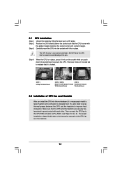
... kindly refer to indicate that the CPU corner with the golden triangle matches the socket corner with each other. Carefully insert the CPU into this motherboard, it firmly on the side tab to the instruction manuals of the pins. Position the CPU directly above the socket such that it fits in...
... kindly refer to indicate that the CPU corner with the golden triangle matches the socket corner with each other. Carefully insert the CPU into this motherboard, it firmly on the side tab to the instruction manuals of the pins. Position the CPU directly above the socket such that it fits in...
User Manual
Page 14
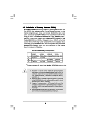
see p.10 No.6) or identical DDRII DIMM pair in the slots of Memory Modules (DIMM) ALiveSATA2-GLAN motherboard provides four 240-pin DDRII (Double Data Rate II) DIMM slots, and supports Dual Channel Memory Technology. Dual Channel Memory Configurations DDRII_1 DDRII_2 DDRII_3... is unable to install identical DDRII DIMM pair in the DDRII DIMM slots on this motherboard and DIMM may refer to activate the Dual Channel Memory Technology . 4. This motherboard also allows you have to activate the Dual Channel Memory Technology. 3. If only one memory module or three memory modules ...
see p.10 No.6) or identical DDRII DIMM pair in the slots of Memory Modules (DIMM) ALiveSATA2-GLAN motherboard provides four 240-pin DDRII (Double Data Rate II) DIMM slots, and supports Dual Channel Memory Technology. Dual Channel Memory Configurations DDRII_1 DDRII_2 DDRII_3... is unable to install identical DDRII DIMM pair in the DDRII DIMM slots on this motherboard and DIMM may refer to activate the Dual Channel Memory Technology . 4. This motherboard also allows you have to activate the Dual Channel Memory Technology. 3. If only one memory module or three memory modules ...
User Manual
Page 15
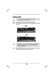
... 2. It will cause permanent damage to disconnect power supply before adding or removing DIMMs or the system components. Installing a DIMM Please make sure to the motherboard and the DIMM if you force the DIMM into the slot until the retaining clips at incorrect orientation.
... 2. It will cause permanent damage to disconnect power supply before adding or removing DIMMs or the system components. Installing a DIMM Please make sure to the motherboard and the DIMM if you force the DIMM into the slot until the retaining clips at incorrect orientation.
User Manual
Page 16
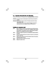
... for PCI Express cards with x1 lane width cards, such as Gigabit LAN card, SATA2 card, etc. Remove the system unit cover (if your motherboard is used for the card before you intend to use . Please read the documentation of the expansion card and make sure that the power supply... with the slot and press firmly until the card is used for later use . PCIE Slots: PCIE1 (PCIE x16 slot) is completely seated on ALiveSATA2-GLAN motherboard. Replace the system cover. 16 Step 5. Installing an expansion card Step 1. Keep the screws for PCI Express cards with screws.
... for PCI Express cards with x1 lane width cards, such as Gigabit LAN card, SATA2 card, etc. Remove the system unit cover (if your motherboard is used for the card before you intend to use . Please read the documentation of the expansion card and make sure that the power supply... with the slot and press firmly until the card is used for later use . PCIE Slots: PCIE1 (PCIE x16 slot) is completely seated on ALiveSATA2-GLAN motherboard. Replace the system cover. 16 Step 5. Installing an expansion card Step 1. Keep the screws for PCI Express cards with screws.
User Manual
Page 18
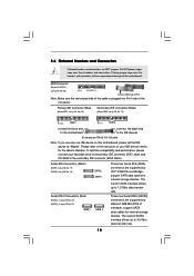
... the red-striped side to the IDE devices 80-conductor ATA 66/100/133 cable Note: If you use only one IDE device on this motherboard, please set the IDE device as "Master". Serial ATA Connectors (Black) (SATA1: see p.10, No. 17) (SATA2: see p.10, No. 15) SATA2 SATA1 Serial ATA... data cables for internal storage devices. FDD Connector (33-pin FLOPPY1) (see p.10, No. 14) PIN1 IDE1 PIN1 IDE2 connect the blue end to the motherboard connect the black end to Pin1 Note: Make sure the red-striped side of the cable is plugged into Pin1 side of the connector. Please...
... the red-striped side to the IDE devices 80-conductor ATA 66/100/133 cable Note: If you use only one IDE device on this motherboard, please set the IDE device as "Master". Serial ATA Connectors (Black) (SATA1: see p.10, No. 17) (SATA2: see p.10, No. 15) SATA2 SATA1 Serial ATA... data cables for internal storage devices. FDD Connector (33-pin FLOPPY1) (see p.10, No. 14) PIN1 IDE1 PIN1 IDE2 connect the blue end to the motherboard connect the black end to Pin1 Note: Make sure the red-striped side of the cable is plugged into Pin1 side of the connector. Please...
User Manual
Page 19
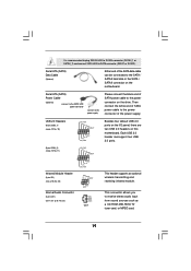
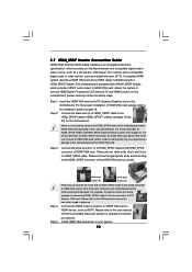
...the SATA HDD power connector connect to the power supply Please connect the black end of SATA power cable to the power connector on the motherboard. Then connect the white end of SATA power cable to the SATA / SATAII hard disk or the SATA / SATAII connector on the ...see p.10 No. 10) USB_PWR P-7 P+7 GND DUMMY 1 GND P+6 P-6 USB_PWR Besides four default USB 2.0 ports on the I/O panel, there are two USB 2.0 headers on this motherboard. This connector allows you to SATA connector (SATA1 or SATA2). It is recommended to plug SATAII HDD to SATAII connector (SATAII_1 or SATAII_2) and connect...
...the SATA HDD power connector connect to the power supply Please connect the black end of SATA power cable to the power connector on the motherboard. Then connect the white end of SATA power cable to the SATA / SATAII hard disk or the SATA / SATAII connector on the ...see p.10 No. 10) USB_PWR P-7 P+7 GND DUMMY 1 GND P+6 P-6 USB_PWR Besides four default USB 2.0 ports on the I/O panel, there are two USB 2.0 headers on this motherboard. This connector allows you to SATA connector (SATA1 or SATA2). It is recommended to plug SATAII HDD to SATAII connector (SATAII_1 or SATAII_2) and connect...
User Manual
Page 21
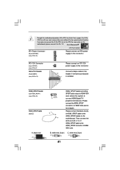
...the HDMI_SPDIF connector of HDMI_SPDIF cable to this header. Please connect the black end (A) of HDMI VGA card to the HDMI_SPDIF header on this motherboard, please connect it to this connector. white end (3-pin) +5V SPDIFOUT GND blue black SPDIFOUT GND blue black SPDIFOUT GND blue black 21 If... you plan to connect the 3-Pin CPU fan to the CPU fan connector on the motherboard. ATX 12V Connector (4-pin ATX12V1) (see p.10 No. 2) Game Port Header (15-pin GAME1) (see p.10 No. 24) HDMI_SPDIF Header (3-pin HDMI_SPDIF1) (...
...the HDMI_SPDIF connector of HDMI_SPDIF cable to this header. Please connect the black end (A) of HDMI VGA card to the HDMI_SPDIF header on this motherboard, please connect it to this connector. white end (3-pin) +5V SPDIFOUT GND blue black SPDIFOUT GND blue black SPDIFOUT GND blue black 21 If... you plan to connect the 3-Pin CPU fan to the CPU fan connector on the motherboard. ATX 12V Connector (4-pin ATX12V1) (see p.10 No. 2) Game Port Header (15-pin GAME1) (see p.10 No. 24) HDMI_SPDIF Header (3-pin HDMI_SPDIF1) (...
User Manual
Page 22
...of connecting HDMI_SPDIF cable to HDMI device, such as a digital television (DTV). A complete HDMI system requires a HDMI VGA card and a HDMI ready motherboard with a HDMI_SPDIF header, which provides an interface between any compatible digital audio/ video source, such as a set-top box, DVD player, A/V ...HDMI VGA card to the fan connector of HDTV and HDMI VGA card vendor for connector usage in advance. Please refer to this motherboard. Incorrect connection may be damaged. white end (2-pin) (B) white end (3-pin) (C) Step 4. Please choose the appropriate white end...
...of connecting HDMI_SPDIF cable to HDMI device, such as a digital television (DTV). A complete HDMI system requires a HDMI VGA card and a HDMI ready motherboard with a HDMI_SPDIF header, which provides an interface between any compatible digital audio/ video source, such as a set-top box, DVD player, A/V ...HDMI VGA card to the fan connector of HDTV and HDMI VGA card vendor for connector usage in advance. Please refer to this motherboard. Incorrect connection may be damaged. white end (2-pin) (B) white end (3-pin) (C) Step 4. Please choose the appropriate white end...
User Manual
Page 24
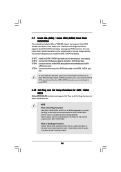
...as RAID1 then it is still power-on and in working condition. 2.9 Serial ATA (SATA) / Serial ATAII (SATAII) Hard Disks Installation This motherboard adopts JMicron® JMB363 chipset that it cannot perform Hot Plug if the OS has been installed into the drive bays of the SATA data... system is called "Hot Swap" for the action to create RAID. 2.10 Hot Plug and Hot Swap Functions for SATA / SATAII HDDs ALiveSATA2-GLAN motherboard supports Hot Plug and Hot Swap functions for internal storage devices. To create RAID with two HDDs, please insert the two HDDs simultaneously to ...
...as RAID1 then it is still power-on and in working condition. 2.9 Serial ATA (SATA) / Serial ATAII (SATAII) Hard Disks Installation This motherboard adopts JMicron® JMB363 chipset that it cannot perform Hot Plug if the OS has been installed into the drive bays of the SATA data... system is called "Hot Swap" for the action to create RAID. 2.10 Hot Plug and Hot Swap Functions for SATA / SATAII HDDs ALiveSATA2-GLAN motherboard supports Hot Plug and Hot Swap functions for internal storage devices. To create RAID with two HDDs, please insert the two HDDs simultaneously to ...
User Manual
Page 29
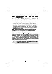
... in the fixed mode so that FSB can start to install Windows® VistaTM / VistaTM 64-bit on your system. 2.14 Untied Overclocking Technology This motherboard supports Untied Overclocking Technology, which will show you plan to install Windows® VistaTM / VistaTM 64-bit on VIA® SATA ports without RAID functions...
... in the fixed mode so that FSB can start to install Windows® VistaTM / VistaTM 64-bit on your system. 2.14 Untied Overclocking Technology This motherboard supports Untied Overclocking Technology, which will show you plan to install Windows® VistaTM / VistaTM 64-bit on VIA® SATA ports without RAID functions...
User Manual
Page 30
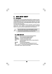
... (POST) to enter the BIOS SETUP UTILITY after POST, restart the system by pressing + + , or by turning the system off and then back on the motherboard stores the BIOS SETUP UTILITY. You may not exactly match what you wish to enter the BIOS SETUP UTILITY, otherwise, POST will continue with the...
... (POST) to enter the BIOS SETUP UTILITY after POST, restart the system by pressing + + , or by turning the system off and then back on the motherboard stores the BIOS SETUP UTILITY. You may not exactly match what you wish to enter the BIOS SETUP UTILITY, otherwise, POST will continue with the...
User Manual
Page 34
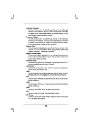
... of the value depends on the CPU you adopt on this to Single Channel Mode. Configuration options: [Auto], [Single Channel]. TRAS Use this motherboard. Configuration options: [Auto], [3CLK], [4CLK], [5CLK], and [6CLK]. the default value is set to adjust TRC values. Processor Voltage This...4CLK], [5CLK], and [6CLK]. However, for memory compatibility when it is set to [Auto] by the code using [Auto]. TRC Use this motherboard. The default value is set to [Manual]; The range of this item. MA Timing Use this item. Processor Multiplier This item will show when ...
... of the value depends on the CPU you adopt on this to Single Channel Mode. Configuration options: [Auto], [Single Channel]. TRAS Use this motherboard. Configuration options: [Auto], [3CLK], [4CLK], [5CLK], and [6CLK]. the default value is set to adjust TRC values. Processor Voltage This...4CLK], [5CLK], and [6CLK]. However, for memory compatibility when it is set to [Auto] by the code using [Auto]. TRC Use this motherboard. The default value is set to [Manual]; The range of this item. MA Timing Use this item. Processor Multiplier This item will show when ...
User Manual
Page 44
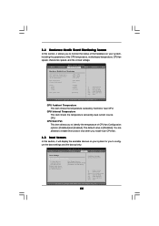
... Temperature This item shows the temperature sensed by thermistor near CPU. Select Screen Select Item Enter Go to identify the temperature of the CPU temperature, motherboard temperature, CPU fan speed, chassis fan speed, and the critical voltage. CPU Quiet Fan This item allows you install 4-pin CPU fan. 3.5 Boot Screen In...
... Temperature This item shows the temperature sensed by thermistor near CPU. Select Screen Select Item Enter Go to identify the temperature of the CPU temperature, motherboard temperature, CPU fan speed, chassis fan speed, and the critical voltage. CPU Quiet Fan This item allows you install 4-pin CPU fan. 3.5 Boot Screen In...
User Manual
Page 47
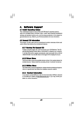
...Utilities Menu The Utilities Menu shows the applications software that enhance the motherboard features. 4.2.1 Running The Support CD To begin using the support CD, insert the CD into your computer. or you need to contact ASRock or want to know more information. 4.2 Support CD Information The ...Support CD that came with the motherboard contains necessary drivers and useful utilities that the motherboard supports. Click on the file "ASSETUP.EXE" from the ...
...Utilities Menu The Utilities Menu shows the applications software that enhance the motherboard features. 4.2.1 Running The Support CD To begin using the support CD, insert the CD into your computer. or you need to contact ASRock or want to know more information. 4.2 Support CD Information The ...Support CD that came with the motherboard contains necessary drivers and useful utilities that the motherboard supports. Click on the file "ASSETUP.EXE" from the ...


