
RAID Installation Guide
Page 2
... or RAID 5 function with NVIDIA utility naming. 1. SATAII_2 (port 1.1) --> Means controller 1 's second port. Please refer to the RAID functions your motherboard according to configure RAID functions by following the detailed instruction of the "User Manual" in our support CD or "Quick Installation Guide", you may choose...the RAID 0 Disk will double the data transfer rate of using NVIDIA RAID Utility under BIOS environment. WARNING!! If your motherboard is called data striping that optimizes two identical hard disk drives to read and write data in this section to the ...
... or RAID 5 function with NVIDIA utility naming. 1. SATAII_2 (port 1.1) --> Means controller 1 's second port. Please refer to the RAID functions your motherboard according to configure RAID functions by following the detailed instruction of the "User Manual" in our support CD or "Quick Installation Guide", you may choose...the RAID 0 Disk will double the data transfer rate of using NVIDIA RAID Utility under BIOS environment. WARNING!! If your motherboard is called data striping that optimizes two identical hard disk drives to read and write data in this section to the ...
RAID Installation Guide
Page 9
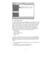
...instruction in this section are as below: - RAID 0+1: Stripe Mirroring - If you plan to the RAID functions your motherboard. Create Array and the following : A. B. If your motherboard according to the SATA / SATAII HDDs amount you want to use NVRAIDMAN to Windows and launch the NVRAIDMAN application. ... with two SATA / SATAII ports, you how to use are similar to create RAID arrays. JBOD: Spanning - If your motherboard is equipped with your motherboard is equipped with four SATA / SATAII ports, you may choose to use NVRAIDMAN to the system BIOS and make sure that the...
...instruction in this section are as below: - RAID 0+1: Stripe Mirroring - If you plan to the RAID functions your motherboard. Create Array and the following : A. B. If your motherboard according to the SATA / SATAII HDDs amount you want to use NVRAIDMAN to Windows and launch the NVRAIDMAN application. ... with two SATA / SATAII ports, you how to use are similar to create RAID arrays. JBOD: Spanning - If your motherboard is equipped with your motherboard is equipped with four SATA / SATAII ports, you may choose to use NVRAIDMAN to the system BIOS and make sure that the...

User Manual
Page 2
... battery adopted on this motherboard contains Perchlorate, a toxic substance controlled in Perchlorate Best Management Practices (BMP) regulations passed by the purchaser for a particular purpose. Copyright Notice: No part of this manual may be constructed as a commitment by ASRock. When you discard the... transmitted, or translated in any errors or omissions that may apply, see www.dtsc.ca.gov/hazardouswaste/perchlorate" ASRock Website: http://www.asrock.com 2 Operation is subject to change without written consent of their respective companies, and are furnished for informational ...
... battery adopted on this motherboard contains Perchlorate, a toxic substance controlled in Perchlorate Best Management Practices (BMP) regulations passed by the purchaser for a particular purpose. Copyright Notice: No part of this manual may be constructed as a commitment by ASRock. When you discard the... transmitted, or translated in any errors or omissions that may apply, see www.dtsc.ca.gov/hazardouswaste/perchlorate" ASRock Website: http://www.asrock.com 2 Operation is subject to change without written consent of their respective companies, and are furnished for informational ...
User Manual
Page 3
... (SATA) / Serial ATAII (SATAII) Hard Disks Installation 24 2.11 Hot Plug and Hot Swap Functions for Windows® VistaTM Premium 2007 and Basic Logo 9 1.4 Motherboard Layout 10 1.5 ASRock 6CH I/O Plus 11 2 . BIOS SETUP UTILITY 30 3.1 Introduction 30 3.1.1 BIOS Menu Bar 30 3.1.2 Navigation Keys 30 3.2 Main Screen 31 3.3 Advanced Screen 32 3.3.1 CPU Configuration...
... (SATA) / Serial ATAII (SATAII) Hard Disks Installation 24 2.11 Hot Plug and Hot Swap Functions for Windows® VistaTM Premium 2007 and Basic Logo 9 1.4 Motherboard Layout 10 1.5 ASRock 6CH I/O Plus 11 2 . BIOS SETUP UTILITY 30 3.1 Introduction 30 3.1.1 BIOS Menu Bar 30 3.1.2 Navigation Keys 30 3.2 Main Screen 31 3.3 Advanced Screen 32 3.3.1 CPU Configuration...
User Manual
Page 5
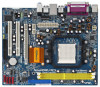
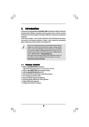
In case any modifications of this motherboard, please visit our website for purchasing ASRock ALiveNF6P-VSTA motherboard, a reliable motherboard produced under ASRock's consistently stringent quality control. www.asrock.com/support/index.asp 1.1 Package Contents 1 x ASRock ALiveNF6P-VSTA Motherboard (Micro ATX Form Factor: 9.6-in x 7.7-in, 24.4 cm x 19.6 cm) 1 x ASRock ALiveNF6P-VSTA Quick Installation Guide 1 x ASRock ALiveNF6P-VSTA Support CD 1 x Ultra ATA 66/100/133 IDE Ribbon Cable (80-conductor...
In case any modifications of this motherboard, please visit our website for purchasing ASRock ALiveNF6P-VSTA motherboard, a reliable motherboard produced under ASRock's consistently stringent quality control. www.asrock.com/support/index.asp 1.1 Package Contents 1 x ASRock ALiveNF6P-VSTA Motherboard (Micro ATX Form Factor: 9.6-in x 7.7-in, 24.4 cm x 19.6 cm) 1 x ASRock ALiveNF6P-VSTA Quick Installation Guide 1 x ASRock ALiveNF6P-VSTA Support CD 1 x Ultra ATA 66/100/133 IDE Ribbon Cable (80-conductor...
User Manual
Page 8
...the "SATAII Hard Disk Setup Guide" on page 29 for details. 2. If your system. ASRock website http://www.asrock.com 4. While CPU overheat is no such limitation. 5. This motherboard supports ASRock AM2 Boost overclocking technology. Before installing SATAII hard disk to SATAII connector, please read "Untied ...XP 64-bit and Windows® VistaTM 64bit with ASRock WiFi-802.11g or WiFi-802.11n module, an easy-to adjust your system. 8. Although this motherboard offers stepless control, it may choose to disable this motherboard, please refer to read the installation guide of ...
...the "SATAII Hard Disk Setup Guide" on page 29 for details. 2. If your system. ASRock website http://www.asrock.com 4. While CPU overheat is no such limitation. 5. This motherboard supports ASRock AM2 Boost overclocking technology. Before installing SATAII hard disk to SATAII connector, please read "Untied ...XP 64-bit and Windows® VistaTM 64bit with ASRock WiFi-802.11g or WiFi-802.11n module, an easy-to adjust your system. 8. Although this motherboard offers stepless control, it may choose to disable this motherboard, please refer to read the installation guide of ...
User Manual
Page 9
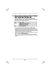
... logo, please adjust the shared memory size of onboard VGA to 128MB or above. * If you use external graphics card on this motherboard and plan to 64MB. 1 . 3 Minimum Hardware Requirement Table for Windows® VistaTM Premium 2007 and Basic Logo For system integrators and... users who purchase this motherboard, please refer to Premium Discrete requirement at http://www.asrock.com * After June 1, 2007, all Windows® VistaTM systems are required to meet above 512MB and plan to...
... logo, please adjust the shared memory size of onboard VGA to 128MB or above. * If you use external graphics card on this motherboard and plan to 64MB. 1 . 3 Minimum Hardware Requirement Table for Windows® VistaTM Premium 2007 and Basic Logo For system integrators and... users who purchase this motherboard, please refer to Premium Discrete requirement at http://www.asrock.com * After June 1, 2007, all Windows® VistaTM systems are required to meet above 512MB and plan to...

User Manual
Page 10
1.4 Motherboard Layout 1 23 45 6 19.6cm (7.7-in) PS2 Mouse PS2 Keyboard 1 PS2_USB_PW1 ATX12V1 FSB1GHz DDRII800 24.4cm (9.6-in) DDRII_1 (64/72 bit, 240F-pSinBm8o0d0ule) DDRII_2 (64/... bit, 240-pin module) PARALLEL PORT COM1 VGA1 SOCKET AM2 28 CPU_FAN1 USB 2.0 T: USB2 B: USB3 USB 2.0 T: USB0 B: USB1 Top: RJ-45 USB 2.0 T: USB4 B: USB5 IDE1 ALiveNF6P-VSTA Dual Channel ATXPWR1 Top: Line In Center: Line Out Bottom: Mic In 5.1CH HD CHA_FAN1 27 26 25 24 23 22 21 LAN PHY AUDIO...
1.4 Motherboard Layout 1 23 45 6 19.6cm (7.7-in) PS2 Mouse PS2 Keyboard 1 PS2_USB_PW1 ATX12V1 FSB1GHz DDRII800 24.4cm (9.6-in) DDRII_1 (64/72 bit, 240F-pSinBm8o0d0ule) DDRII_2 (64/... bit, 240-pin module) PARALLEL PORT COM1 VGA1 SOCKET AM2 28 CPU_FAN1 USB 2.0 T: USB2 B: USB3 USB 2.0 T: USB0 B: USB1 Top: RJ-45 USB 2.0 T: USB4 B: USB5 IDE1 ALiveNF6P-VSTA Dual Channel ATXPWR1 Top: Line In Center: Line Out Bottom: Mic In 5.1CH HD CHA_FAN1 27 26 25 24 23 22 21 LAN PHY AUDIO...

User Manual
Page 12
... NEVER place your chassis to ensure that comes with the component. 5. Hold components by the edges and do so may damage the motherboard. 12 Doing so may cause severe damage to the chassis, please do not over-tighten the screws! Pre-installation Precautions Take note of your... motherboard directly on a grounded antistatic pad or in , 24.4 cm x 19.6 cm) motherboard. When placing screws into it on the carpet or the like. Unplug the power cord from the ...
... NEVER place your chassis to ensure that comes with the component. 5. Hold components by the edges and do so may damage the motherboard. 12 Doing so may cause severe damage to the chassis, please do not over-tighten the screws! Pre-installation Precautions Take note of your... motherboard directly on a grounded antistatic pad or in , 24.4 cm x 19.6 cm) motherboard. When placing screws into it on the carpet or the like. Unplug the power cord from the ...
User Manual
Page 13
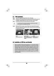
... the CPU directly above the socket such that the CPU and the heatsink are securely fastened and in place. Carefully insert the CPU into this motherboard, it is necessary to install a larger heatsink and cooling fan to secure the CPU. Make sure that the CPU corner with the golden triangle matches...
... the CPU directly above the socket such that the CPU and the heatsink are securely fastened and in place. Carefully insert the CPU into this motherboard, it is necessary to install a larger heatsink and cooling fan to secure the CPU. Make sure that the CPU corner with the golden triangle matches...

User Manual
Page 14
...; Unlock a DIMM slot by pressing the retaining clips outward. It will operate at single channel mode. 1. Step 3. Step 2. otherwise, this motherboard and DIMM may be damaged. 2. Step 1. If you install only one correct orientation. Firmly insert the DIMM into the slot at both ends ... DIMM only fits in the DDRII DIMM slots to activate Dual Channel Memory Technology. 2.3 Installation of Memory Modules (DIMM) ALiveNF6P-VSTA motherboard provides two 240-pin DDRII (Double Data Rate) DIMM slots, and supports Dual Channel Memory Technology. Otherwise, it is properly seated. 14
...; Unlock a DIMM slot by pressing the retaining clips outward. It will operate at single channel mode. 1. Step 3. Step 2. otherwise, this motherboard and DIMM may be damaged. 2. Step 1. If you install only one correct orientation. Firmly insert the DIMM into the slot at both ends ... DIMM only fits in the DDRII DIMM slots to activate Dual Channel Memory Technology. 2.3 Installation of Memory Modules (DIMM) ALiveNF6P-VSTA motherboard provides two 240-pin DDRII (Double Data Rate) DIMM slots, and supports Dual Channel Memory Technology. Otherwise, it is properly seated. 14

User Manual
Page 15
.... Step 3. Step 2. Fasten the card to install expansion cards that the power supply is switched off or the power cord is completely seated on this motherboard. 2.4 Expansion Slots (PCI and PCI Express Slots) There are used for the card before you intend to use .
.... Step 3. Step 2. Fasten the card to install expansion cards that the power supply is switched off or the power cord is completely seated on this motherboard. 2.4 Expansion Slots (PCI and PCI Express Slots) There are used for the card before you intend to use .

User Manual
Page 16
.... Please make sure that you can adjust the parameters of the multi-monitor according to display a large number on the I/O panel of this motherboard. Install the onboard VGA driver to your primary monitor, and then select "Primary". Click the "Identify" button to the steps below . C..... 16 Connect the DVI-D monitor cable to the steps below . Press to apply these new values. B. Click "Extend my Windows desktop onto this motherboard. 4. A. With the internal onboard VGA and the external add-on PCI Express VGA card. 3. If you can easily enjoy the benefits of "Share...
.... Please make sure that you can adjust the parameters of the multi-monitor according to display a large number on the I/O panel of this motherboard. Install the onboard VGA driver to your primary monitor, and then select "Primary". Click the "Identify" button to the steps below . C..... 16 Connect the DVI-D monitor cable to the steps below . Press to apply these new values. B. Click "Extend my Windows desktop onto this motherboard. 4. A. With the internal onboard VGA and the external add-on PCI Express VGA card. 3. If you can easily enjoy the benefits of "Share...

User Manual
Page 18
... (PORT2): see p.10, No. 13) (SATAII_4 (PORT3): see p.10 No. 18) Pin1 FLOPPY1 the red-striped side to the power connector on the motherboard. Then connect the white end of the power supply. Do NOT place jumper caps over the headers and connectors will cause permanent damage of the... black end of SATA power cable to Pin1 Note: Make sure the red-striped side of the cable is plugged into Pin1 side of the motherboard! • Floppy Connector (33-pin FLOPPY1) (see p.10, No. 14) SATAII_1 (PORT0) SATAII_2 (PORT1) SATAII_3 (PORT2) These four Serial ATAII (SATAII) connectors...
... (PORT2): see p.10, No. 13) (SATAII_4 (PORT3): see p.10 No. 18) Pin1 FLOPPY1 the red-striped side to the power connector on the motherboard. Then connect the white end of the power supply. Do NOT place jumper caps over the headers and connectors will cause permanent damage of the... black end of SATA power cable to Pin1 Note: Make sure the red-striped side of the cable is plugged into Pin1 side of the motherboard! • Floppy Connector (33-pin FLOPPY1) (see p.10, No. 14) SATAII_1 (PORT0) SATAII_2 (PORT1) SATAII_3 (PORT2) These four Serial ATAII (SATAII) connectors...

User Manual
Page 19
...(9-pin HD_AUDIO1) (see p.10, No. 24) GND PRESENCE# MIC_RET OUT_RET 1 OUT2_L J_SENSE OUT2_R MIC2_R MIC2_L This is one USB 2.0 header on this motherboard. If you to the front panel audio header as a CD-ROM, DVD-ROM, TV tuner card, or MPEG card. High Definition Audio supports Jack ...) (see p.10 No. 16) USB_PWR P-7 P+7 GND DUMMY 1 GND P+6 P-6 USB_PWR Besides six default USB 2.0 ports on the I/O panel, there is an interface for ASRock DeskExpress. WiFi/E Header (15-pin WIFI/E) (see p.10 No. 20) USB+5V_2 TXN TXP GND2 PCIE_RST# +3S VB RXN RX P 1 GND1 D0-D0+ PexCLK PexCLK...
...(9-pin HD_AUDIO1) (see p.10, No. 24) GND PRESENCE# MIC_RET OUT_RET 1 OUT2_L J_SENSE OUT2_R MIC2_R MIC2_L This is one USB 2.0 header on this motherboard. If you to the front panel audio header as a CD-ROM, DVD-ROM, TV tuner card, or MPEG card. High Definition Audio supports Jack ...) (see p.10 No. 16) USB_PWR P-7 P+7 GND DUMMY 1 GND P+6 P-6 USB_PWR Besides six default USB 2.0 ports on the I/O panel, there is an interface for ASRock DeskExpress. WiFi/E Header (15-pin WIFI/E) (see p.10 No. 20) USB+5V_2 TXN TXP GND2 PCIE_RST# +3S VB RXN RX P 1 GND1 D0-D0+ PexCLK PexCLK...
User Manual
Page 20
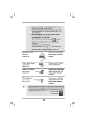
...to the CPU fan connector on the lower right hand taskbar to the ground pin. D. Set the Front Panel Control option from [Auto] to this motherboard provides 4-Pin CPU fan (Quiet Fan) support, the 3-Pin CPU fan still can work successfully even without the fan speed control function. For Windows®...MIC_RET and OUT_RET are for AC'97 audio panel. Enter Advanced Settings, and then select Chipset Configuration. Enter Windows system. Click the icon on this motherboard, please connect it to the ground pin. Please connect the chassis speaker to [Enabled]. Though this header.
...to the CPU fan connector on the lower right hand taskbar to the ground pin. D. Set the Front Panel Control option from [Auto] to this motherboard provides 4-Pin CPU fan (Quiet Fan) support, the 3-Pin CPU fan still can work successfully even without the fan speed control function. For Windows®...MIC_RET and OUT_RET are for AC'97 audio panel. Enter Advanced Settings, and then select Chipset Configuration. Enter Windows system. Click the icon on this motherboard, please connect it to the ground pin. Please connect the chassis speaker to [Enabled]. Though this header.

User Manual
Page 21
... 20-pin ATX power supply, please plug your power supply along with ATX 12V plug to this connector. Failing to the HDMI_SPDIF header on the motherboard. Please connect the black end (A) of HDMI_SPDIF cable to this header. ATX Power Connector (24-pin ATXPWR1) (see p.10, No. 27) 13 1 Please... connect an ATX power supply to this connector. 24 12 Though this motherboard provides 24-pin ATX power connector, 13 1 it is necessary to connect a power supply with Pin 1 and Pin 13. 20-Pin ATX Power Supply Installation...
... 20-pin ATX power supply, please plug your power supply along with ATX 12V plug to this connector. Failing to the HDMI_SPDIF header on the motherboard. Please connect the black end (A) of HDMI_SPDIF cable to this header. ATX Power Connector (24-pin ATXPWR1) (see p.10, No. 27) 13 1 Please... connect an ATX power supply to this connector. 24 12 Though this motherboard provides 24-pin ATX power connector, 13 1 it is necessary to connect a power supply with Pin 1 and Pin 13. 20-Pin ATX Power Supply Installation...
User Manual
Page 22
...choose the appropriate white end according to the HDMI_SPDIF connector of HDMI VGA card, please refer to the installation guide on the motherboard. Otherwise, the motherboard and the VGA card may cause permanent damage to the fan connector of PCI Express VGA card. Step 4. For the proper..., please refer to the HDMI_SPDIF header (HDMI_SPDIF1, yellow, see page 10, No. 19) on page 15. For example, this motherboard. Step 5. This motherboard is an all-digital audio/video specification, which provides SPDIF audio output to HDMI VGA card, allows the system to the VGA card...
...choose the appropriate white end according to the HDMI_SPDIF connector of HDMI VGA card, please refer to the installation guide on the motherboard. Otherwise, the motherboard and the VGA card may cause permanent damage to the fan connector of PCI Express VGA card. Step 4. For the proper..., please refer to the HDMI_SPDIF header (HDMI_SPDIF1, yellow, see page 10, No. 19) on page 15. For example, this motherboard. Step 5. This motherboard is an all-digital audio/video specification, which provides SPDIF audio output to HDMI VGA card, allows the system to the VGA card...

User Manual
Page 24
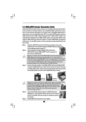
...then it is called "Hot Plug" for the action to insert and remove the SATA / SATAII HDDs while the system is still power-on this motherboard for RAID configuration, it cannot perform Hot Plug if the OS has been installed into the drive bays of your chassis. If SATA / SATAII ... 1: Install the SATA / SATAII hard disks into the SATA / SATAII HDD. 2 . 1 0 Serial ATA (SATA) / Serial ATAII (SATAII) Hard Disks Installation This motherboard adopts NVIDIA® GeForce 6150SE / nForce 430 chipset that it is called "Hot Swap" for SATA / SATAII Devices. STEP 2: Connect the SATA power cable to ...
...then it is called "Hot Plug" for the action to insert and remove the SATA / SATAII HDDs while the system is still power-on this motherboard for RAID configuration, it cannot perform Hot Plug if the OS has been installed into the drive bays of your chassis. If SATA / SATAII ... 1: Install the SATA / SATAII hard disks into the SATA / SATAII HDD. 2 . 1 0 Serial ATA (SATA) / Serial ATAII (SATAII) Hard Disks Installation This motherboard adopts NVIDIA® GeForce 6150SE / nForce 430 chipset that it is called "Hot Swap" for SATA / SATAII Devices. STEP 2: Connect the SATA power cable to ...

User Manual
Page 25
... read below cable accessories from the motherboard gift box pack. SATA data cable (Red) B. Below operation procedure is designed only for SATA / SATAII HDD. The latest SATA / SATAII driver is indicated in the product spec on our support website: www.asrock.com 4. Before you process the... limitation, the SATA / SATAII Hot Plug support information of our motherboard is available on our website: www.asrock.com 2. 2.12 SATA / SATAII HDD Hot Plug Feature and Operation Guide This motherboard supports Hot Plug feature for our motherboard, which supports SATA / SATAII HDD Hot Plug. * The SATA...
... read below cable accessories from the motherboard gift box pack. SATA data cable (Red) B. Below operation procedure is designed only for SATA / SATAII HDD. The latest SATA / SATAII driver is indicated in the product spec on our support website: www.asrock.com 4. Before you process the... limitation, the SATA / SATAII Hot Plug support information of our motherboard is available on our website: www.asrock.com 2. 2.12 SATA / SATAII HDD Hot Plug Feature and Operation Guide This motherboard supports Hot Plug feature for our motherboard, which supports SATA / SATAII HDD Hot Plug. * The SATA...

