
RAID Installation Guide
Page 2
This section includes examples of the "User Manual" in our support CD or "Quick Installation Guide", you make a SATA / SATAII driver diskette, press to enter BIOS setup to set . Please refer to the ...
This section includes examples of the "User Manual" in our support CD or "Quick Installation Guide", you make a SATA / SATAII driver diskette, press to enter BIOS setup to set . Please refer to the ...

User Manual
Page 1
ALiveNF6P-VSTA User Manual Version 1.1 Published November 2007 Copyright©2007 ASRock INC. All rights reserved. 1
ALiveNF6P-VSTA User Manual Version 1.1 Published November 2007 Copyright©2007 ASRock INC. All rights reserved. 1

User Manual
Page 2
...without notice, and should not be liable for any interference received, including interference that may appear in this manual. With respect to the contents of this manual, ASRock does not provide warranty of any kind, either expressed or implied, including but not limited to the implied... warranties or conditions of merchantability or fitness for any defect or error in the manual or product. ASRock assumes no event shall ASRock, its directors, officers, employees, or agents be constructed as a commitment by the California Legislature. Operation is ...
...without notice, and should not be liable for any interference received, including interference that may appear in this manual. With respect to the contents of this manual, ASRock does not provide warranty of any kind, either expressed or implied, including but not limited to the implied... warranties or conditions of merchantability or fitness for any defect or error in the manual or product. ASRock assumes no event shall ASRock, its directors, officers, employees, or agents be constructed as a commitment by the California Legislature. Operation is ...
User Manual
Page 5
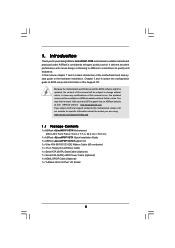
... model you are using. In this manual, chapter 1 and 2 contain introduction of this manual occur, the updated version will be available on ASRock website as well. www.asrock.com/support/index.asp 1.1 Package Contents 1 x ASRock ALiveNF6P-VSTA Motherboard (Micro ATX Form Factor: 9.6-in x 7.7-in, 24.4 cm x 19.6 cm) 1 x ASRock ALiveNF6P-VSTA Quick Installation Guide 1 x ASRock ALiveNF6P-VSTA Support CD 1 x Ultra ATA 66/100...
... model you are using. In this manual, chapter 1 and 2 contain introduction of this manual occur, the updated version will be available on ASRock website as well. www.asrock.com/support/index.asp 1.1 Package Contents 1 x ASRock ALiveNF6P-VSTA Motherboard (Micro ATX Form Factor: 9.6-in x 7.7-in, 24.4 cm x 19.6 cm) 1 x ASRock ALiveNF6P-VSTA Quick Installation Guide 1 x ASRock ALiveNF6P-VSTA Support CD 1 x Ultra ATA 66/100...
User Manual
Page 13
... the socket while you install the CPU into the socket until it fits in place, press it firmly on the side tab to the instruction manuals of the pins. Unlock the socket by lifting the lever up to the CPU FAN connector (CPU_FAN1, see Page 10, No. 28). Carefully insert the...
... the socket while you install the CPU into the socket until it fits in place, press it firmly on the side tab to the instruction manuals of the pins. Unlock the socket by lifting the lever up to the CPU FAN connector (CPU_FAN1, see Page 10, No. 28). Carefully insert the...

User Manual
Page 19
...card. Connect Audio_R (RIN) to OUT2_R and Audio_L (LIN) to install your system. 2. C. Please follow the instruction in our manual and chassis manual to OUT2_L. Connect Ground (GND) to create a wireless environment and enjoy the convenience of audio devices. 1. USB 2.0 Header ...(9-pin USB6_7) (see p.10 No. 16) USB_PWR P-7 P+7 GND DUMMY 1 GND P+6 P-6 USB_PWR Besides six default USB 2.0 ports on the I/O panel, there is an interface for ASRock...
...card. Connect Audio_R (RIN) to OUT2_R and Audio_L (LIN) to install your system. 2. C. Please follow the instruction in our manual and chassis manual to OUT2_L. Connect Ground (GND) to create a wireless environment and enjoy the convenience of audio devices. 1. USB 2.0 Header ...(9-pin USB6_7) (see p.10 No. 16) USB_PWR P-7 P+7 GND DUMMY 1 GND P+6 P-6 USB_PWR Besides six default USB 2.0 ports on the I/O panel, there is an interface for ASRock...
User Manual
Page 22
... For the proper installation of HDMI VGA card, please refer to the installation guide on HDMI VGA card, please refer to the user manual of HDMI_SPDIF connectors on page 15. A complete HDMI system requires a HDMI VGA card and a HDMI ready motherboard with a HDMI_SPDIF header,... install. Incorrect connection may be damaged. Please choose the appropriate white end according to the HDMI_SPDIF connector of HDMI_SPDIF cable to the user manual of PCI Express VGA card. For example, this motherboard and the HDMI VGA card. Step 4. Step 5. Please refer to the HDMI_SPDIF...
... For the proper installation of HDMI VGA card, please refer to the installation guide on HDMI VGA card, please refer to the user manual of HDMI_SPDIF connectors on page 15. A complete HDMI system requires a HDMI VGA card and a HDMI ready motherboard with a HDMI_SPDIF header,... install. Incorrect connection may be damaged. Please choose the appropriate white end according to the HDMI_SPDIF connector of HDMI_SPDIF cable to the user manual of PCI Express VGA card. For example, this motherboard and the HDMI VGA card. Step 4. Step 5. Please refer to the HDMI_SPDIF...

User Manual
Page 25
... SATA / SATAII Hot Plug cannot be damaged under the Hot Plug operation. 3. The latest SATA / SATAII driver is available on our website: www.asrock.com 2. SATA power cable with SATA 15-pin power connector interface A. Even some SATA / SATAII HDDs provide both SATA 15-pin power connector and ...Plug and will be processed. 2. Please make sure the SATA / SATAII driver is indicated in the product spec on our support website: www.asrock.com 4. Make sure to reduce the risk of our motherboard is installed into system properly. Please follow below cable accessories from your dealer or HDD...
... SATA / SATAII Hot Plug cannot be damaged under the Hot Plug operation. 3. The latest SATA / SATAII driver is available on our website: www.asrock.com 2. SATA power cable with SATA 15-pin power connector interface A. Even some SATA / SATAII HDDs provide both SATA 15-pin power connector and ...Plug and will be processed. 2. Please make sure the SATA / SATAII driver is indicated in the product spec on our support website: www.asrock.com 4. Make sure to reduce the risk of our motherboard is installed into system properly. Please follow below cable accessories from your dealer or HDD...
User Manual
Page 33
... adjust PCIE frequency. Boot Failure Guard Enable or disable the feature of Boot Failure Guard. If you will enable ASRock AM2 Boost function, which will be set to [Enabled] as default. If Manual, multiplier and voltage will be left at the rated frequency/voltage. 3.3.1 CPU Configuration BIOS SETUP UTILITY Advanced CPU Configuration...
... adjust PCIE frequency. Boot Failure Guard Enable or disable the feature of Boot Failure Guard. If you will enable ASRock AM2 Boost function, which will be set to [Enabled] as default. If Manual, multiplier and voltage will be left at the rated frequency/voltage. 3.3.1 CPU Configuration BIOS SETUP UTILITY Advanced CPU Configuration...

User Manual
Page 34
... Select Item Change Option General Help Load Defaults Save and Exit Exit v02.54 (C) Copyright 1985-2003, American Megatrends, Inc. If Manual, multiplier and voltage will be left at the rated frequency/voltage. otherwise, it will be hidden. The range of this motherboard.... Voltage [Disabled] [Auto] [200] [100] [Enabled] [Enabled] [Enabled] [Enabled] [Auto] [Enabled] [Disabled] x25.0 5000 MHz 1.350 V [Manual] [x8] [1.500V] If AUTO, multiplier and voltage will be set to system stability or compatibility issue with some memory modules or power supplies. Processor Maximum...
... Select Item Change Option General Help Load Defaults Save and Exit Exit v02.54 (C) Copyright 1985-2003, American Megatrends, Inc. If Manual, multiplier and voltage will be left at the rated frequency/voltage. otherwise, it will be hidden. The range of this motherboard.... Voltage [Disabled] [Auto] [200] [100] [Enabled] [Enabled] [Enabled] [Enabled] [Auto] [Enabled] [Disabled] x25.0 5000 MHz 1.350 V [Manual] [x8] [1.500V] If AUTO, multiplier and voltage will be set to system stability or compatibility issue with some memory modules or power supplies. Processor Maximum...

Quick Installation Guide
Page 4
... Ribbon Cable 1 x Serial ATA (SATA) Data Cable (Optional) 1 x Serial ATA (SATA) HDD Power Cable (Optional) 1 x HDMI_SPDIF Cable (Optional) 1 x "ASRock 6CH I/O Plus" I/O Shield 4 ASRock ALiveNF6P-VSTA Motherboard English More detailed information of this manual will be available on ASRock website as well. In case any modifications of the motherboard and step-bystep installation guide. 1. You may find...
... Ribbon Cable 1 x Serial ATA (SATA) Data Cable (Optional) 1 x Serial ATA (SATA) HDD Power Cable (Optional) 1 x HDMI_SPDIF Cable (Optional) 1 x "ASRock 6CH I/O Plus" I/O Shield 4 ASRock ALiveNF6P-VSTA Motherboard English More detailed information of this manual will be available on ASRock website as well. In case any modifications of the motherboard and step-bystep installation guide. 1. You may find...

Quick Installation Guide
Page 9
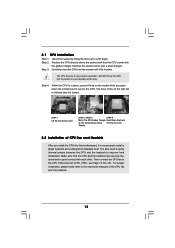
... CPU fan and heatsink vendors. Step 2. When the CPU is locked. For proper installation, please kindly refer to the instruction manuals of the following precautions before you install motherboard components or change any motherboard settings. 1. Unplug the power cord from the wall .... 2.1 CPU Installation Step 1. Carefully insert the CPU into the socket to the motherboard, peripherals, and/or components. 2. English 9 ASRock ALiveNF6P-VSTA Motherboard Doing so may cause severe damage to avoid bending of the pins. Position the CPU directly above the socket such that comes with...
... CPU fan and heatsink vendors. Step 2. When the CPU is locked. For proper installation, please kindly refer to the instruction manuals of the following precautions before you install motherboard components or change any motherboard settings. 1. Unplug the power cord from the wall .... 2.1 CPU Installation Step 1. Carefully insert the CPU into the socket to the motherboard, peripherals, and/or components. 2. English 9 ASRock ALiveNF6P-VSTA Motherboard Doing so may cause severe damage to avoid bending of the pins. Position the CPU directly above the socket such that comes with...

Quick Installation Guide
Page 15
...area network (WLAN) adapter. B. Please follow the instruction in our manual and chassis manual to -use AC'97 audio panel, please install it to Ground (GND). 15 ASRock ALiveNF6P-VSTA Motherboard This header supports WiFi+AP function with ASRock WiFi-802.11g or WiFi-802.11n module, an easy-to ... Panel Audio Header (9-pin HD_AUDIO1) (see p.2, No. 24) Besides six default USB 2.0 ports on the I/O panel, there is an interface for ASRock DeskExpress. This is one USB 2.0 header on the chassis must support HDA to create a wireless environment and enjoy the convenience of audio devices. If you...
...area network (WLAN) adapter. B. Please follow the instruction in our manual and chassis manual to -use AC'97 audio panel, please install it to Ground (GND). 15 ASRock ALiveNF6P-VSTA Motherboard This header supports WiFi+AP function with ASRock WiFi-802.11g or WiFi-802.11n module, an easy-to ... Panel Audio Header (9-pin HD_AUDIO1) (see p.2, No. 24) Besides six default USB 2.0 ports on the I/O panel, there is an interface for ASRock DeskExpress. This is one USB 2.0 header on the chassis must support HDA to create a wireless environment and enjoy the convenience of audio devices. If you...
Quick Installation Guide
Page 18
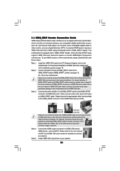
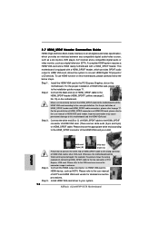
...-digital audio/video specification, which provides SPDIF audio output to HDMI VGA card, allows the system to the VGA card user manual for detailed connection procedures. Incorrect connection may be damaged. Connect the HDMI output connector on the motherboard. For example, this ... may cause permanent damage to the user manual of the HDMI VGA card you install. Make sure to correctly connect the HDMI_SPDIF cable to the motherboard and the HDMI VGA card according to your system. 18 ASRock ALiveNF6P-VSTA Motherboard 2.7 HDMI_SPDIF Header Connection Guide HDMI ...
...-digital audio/video specification, which provides SPDIF audio output to HDMI VGA card, allows the system to the VGA card user manual for detailed connection procedures. Incorrect connection may be damaged. Connect the HDMI output connector on the motherboard. For example, this ... may cause permanent damage to the user manual of the HDMI VGA card you install. Make sure to correctly connect the HDMI_SPDIF cable to the motherboard and the HDMI VGA card according to your system. 18 ASRock ALiveNF6P-VSTA Motherboard 2.7 HDMI_SPDIF Header Connection Guide HDMI ...
Quick Installation Guide
Page 24
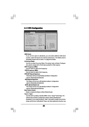
..., please press during the Power-On-Self-Test (POST) to the User Manual (PDF file) contained in your CDROM drive. The Support CD that will display the Main Menu automatically if "AUTORUN" is designed to display the menus. 24 ASRock ALiveNF6P-VSTA Motherboard English It will enhance motherboard features. BIOS Information The Flash Memory...
..., please press during the Power-On-Self-Test (POST) to the User Manual (PDF file) contained in your CDROM drive. The Support CD that will display the Main Menu automatically if "AUTORUN" is designed to display the menus. 24 ASRock ALiveNF6P-VSTA Motherboard English It will enhance motherboard features. BIOS Information The Flash Memory...
