User Manual
Page 3
Installation 12 Pre-installation Precautions 12 2.1 CPU Installation 13 2.2 Installation of CPU Fan and Heatsink 13 2.3 Installation of Memory Modules (DIMM 14 2.4 Expansion Slots (PCI Express, PCI, and HDMR Slots 16 2.5 Easy Multi Monitor Feature 17 2.6 Jumpers Setup 18 2.7 Onboard Headers and Connectors 19 2.8 ...
Installation 12 Pre-installation Precautions 12 2.1 CPU Installation 13 2.2 Installation of CPU Fan and Heatsink 13 2.3 Installation of Memory Modules (DIMM 14 2.4 Expansion Slots (PCI Express, PCI, and HDMR Slots 16 2.5 Easy Multi Monitor Feature 17 2.6 Jumpers Setup 18 2.7 Onboard Headers and Connectors 19 2.8 ...
User Manual
Page 6
.../s) - Max. CPU Frequency Stepless Control (see CAUTION 2) - Micro ATX Form Factor: 9.6-in x 9.6-in, 24.4 cm x 24.4 cm - ASRock AM2 Boost: ASRock Patented Technology to boost memory performance up to -Use USB 2.0 Ports - 1 x RJ-45 Port 6 Dual Channel DDRII Memory Technology (see CAUTION 8) - 2 x PCI slots - 1 x PCI Express x16 slot - 1 x PCI Express x1 slot - 1 x HDMR slot...
.../s) - Max. CPU Frequency Stepless Control (see CAUTION 2) - Micro ATX Form Factor: 9.6-in x 9.6-in, 24.4 cm x 24.4 cm - ASRock AM2 Boost: ASRock Patented Technology to boost memory performance up to -Use USB 2.0 Ports - 1 x RJ-45 Port 6 Dual Channel DDRII Memory Technology (see CAUTION 8) - 2 x PCI slots - 1 x PCI Express x16 slot - 1 x PCI Express x1 slot - 1 x HDMR slot...
User Manual
Page 8
...strongly recommended to enable AMD's Cool 'n' QuietTM technology under Windows® XP and Windows® VistaTM. Before you implement Dual Channel Memory Technology, make sure to read "Untied Overclocking Technology" on page 50 to enable AMD's Cool 'n' QuietTM technology. 2. Enabling this ... Although this function will automatically shutdown. Please read the installation guide of GeForce 6100 / nForce 430. This motherboard supports ASRock AM2 Boost overclocking technology. It should be less than the recommended CPU bus frequencies may affect your system stability, or even...
...strongly recommended to enable AMD's Cool 'n' QuietTM technology under Windows® XP and Windows® VistaTM. Before you implement Dual Channel Memory Technology, make sure to read "Untied Overclocking Technology" on page 50 to enable AMD's Cool 'n' QuietTM technology. 2. Enabling this ... Although this function will automatically shutdown. Please read the installation guide of GeForce 6100 / nForce 430. This motherboard supports ASRock AM2 Boost overclocking technology. It should be less than the recommended CPU bus frequencies may affect your system stability, or even...

User Manual
Page 9
... logo, please adjust the shared memory size of onboard VGA to SATAII mode. Please check the table on page 24 to adjust your SATAII hard disk drive to 64MB. Before installing SATAII hard disk to Premium Discrete requirement at http://www.asrock.com 9 For microphone input, ...this motherboard supports 2-channel, 4-channel, 6-channel, and 8-channel modes. 9. For audio output, this motherboard supports both stereo and mono modes. If you plan to use onboard VGA with total system memory size 512MB and plan to ...
... logo, please adjust the shared memory size of onboard VGA to SATAII mode. Please check the table on page 24 to adjust your SATAII hard disk drive to 64MB. Before installing SATAII hard disk to Premium Discrete requirement at http://www.asrock.com 9 For microphone input, ...this motherboard supports 2-channel, 4-channel, 6-channel, and 8-channel modes. 9. For audio output, this motherboard supports both stereo and mono modes. If you plan to use onboard VGA with total system memory size 512MB and plan to ...
User Manual
Page 10
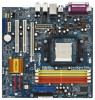
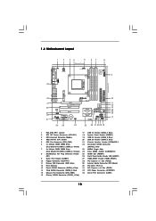
... Floppy Connector (FLOPPY1) 28 PCI Express x1 Slot (PCIE2) 11 Primary IDE Connector (IDE1, Blue) 29 Internal Audio Connector: CD1 (Black) 12 Flash Memory 30 PCI Slots (PCI1- 2) 13 Fourth SATAII Connector (SATAII_4, Red) 31 PCI Express x16 Slot (PCIE1) 14 Third SATAII Connector (SATAII_3, Red) ... 29 28 27 Top: LINE IN Center: FRONT Bottom: MIC IN LAN PHY CD1 AUDIO CODEC HDMI_SPDIF1 1 1 HD_AUDIO1 PCIE1 PCI EXPRESS RAID ALiveNF6G-VSTA PCI1 PCI2 PCIE2 7.1CH HD HDMR1 CMOS BATTERY CLRCMOS1 1 NVIDIA GeForce 6100 / nForce 430 or GeForce 6150SE / nForce 430 Chipset RoHS SATAII_4 ...
... Floppy Connector (FLOPPY1) 28 PCI Express x1 Slot (PCIE2) 11 Primary IDE Connector (IDE1, Blue) 29 Internal Audio Connector: CD1 (Black) 12 Flash Memory 30 PCI Slots (PCI1- 2) 13 Fourth SATAII Connector (SATAII_4, Red) 31 PCI Express x16 Slot (PCIE1) 14 Third SATAII Connector (SATAII_3, Red) ... 29 28 27 Top: LINE IN Center: FRONT Bottom: MIC IN LAN PHY CD1 AUDIO CODEC HDMI_SPDIF1 1 1 HD_AUDIO1 PCIE1 PCI EXPRESS RAID ALiveNF6G-VSTA PCI1 PCI2 PCIE2 7.1CH HD HDMR1 CMOS BATTERY CLRCMOS1 1 NVIDIA GeForce 6100 / nForce 430 or GeForce 6150SE / nForce 430 Chipset RoHS SATAII_4 ...

User Manual
Page 14
...identical DDRII DIMM pair in the slots of orange slots (DDRII_3 and DDRII_4). 2. If you to the Dual Channel Memory Configuration Table below. If a pair of memory modules is NOT installed in the same Dual Channel, for optimal compatibility and reliability, it is recommended to install ... the same color. 2.3 Installation of the same color. This motherboard also allows you want to install a DDR memory module into DDRII slot; If only one memory module or three memory modules are installed in Dual Channel B (DDRII_3 and DDRII_4; It is unable to install identical (the same brand...
...identical DDRII DIMM pair in the slots of orange slots (DDRII_3 and DDRII_4). 2. If you to the Dual Channel Memory Configuration Table below. If a pair of memory modules is NOT installed in the same Dual Channel, for optimal compatibility and reliability, it is recommended to install ... the same color. 2.3 Installation of the same color. This motherboard also allows you want to install a DDR memory module into DDRII slot; If only one memory module or three memory modules are installed in Dual Channel B (DDRII_3 and DDRII_4; It is unable to install identical (the same brand...

User Manual
Page 17
... 17 Connect another D-Sub input monitor cable to page 16 for proper expansion card installation procedures for the second monitor. Enter "Share Memory" option to adjust the memory capability to [16MB], [32MB], [64MB], [128MB], or [256MB] to display a large number on PCI Express VGA card. ... Monitor Feature This motherboard supports Multi Monitor upgrade. Boot your system. Click the "Identify" button to enable the function of the system memory. Select the display icon identified by the number one monitor will always be similar.) A. Please refer to the following steps to be ...
... 17 Connect another D-Sub input monitor cable to page 16 for proper expansion card installation procedures for the second monitor. Enter "Share Memory" option to adjust the memory capability to [16MB], [32MB], [64MB], [128MB], or [256MB] to display a large number on PCI Express VGA card. ... Monitor Feature This motherboard supports Multi Monitor upgrade. Boot your system. Click the "Identify" button to enable the function of the system memory. Select the display icon identified by the number one monitor will always be similar.) A. Please refer to the following steps to be ...

User Manual
Page 31
... bar, and then press to configure your screen. 3.1.1 BIOS Menu Bar The top of the screen has a menu bar with its test routines. The Flash Memory on the system chassis.
... bar, and then press to configure your screen. 3.1.1 BIOS Menu Bar The top of the screen has a menu bar with its test routines. The Flash Memory on the system chassis.

User Manual
Page 32
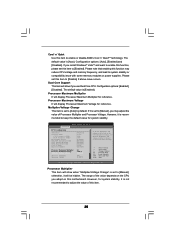
...UTILITY Main Advanced H/W Monitor Boot Security Exit System Overview System Time System Date [17:00:09] [Wed 07/12/2006] BIOS Version : ALiveNF6G-VSTA BIOS P2.00 Processor Type : AMD Athlon(tm) 64 Processor 3400+ (64bit supported) Processor Speed : 2200 MHz Microcode Update : F7A/3A ...L1 Cache Size : 128KB L2 Cache Size : 512KB Total Memory DDRII 1 DDRII 2 DDRII 3 DDRII 4 : 512MB with 64MB shared memory Dual-Channel Memory Mode : 256MB/266MHz (DDRII533) : 256MB/266MHz (DDRII533) : None : None Use [Enter], [TAB] or [SHIFT-TAB...
...UTILITY Main Advanced H/W Monitor Boot Security Exit System Overview System Time System Date [17:00:09] [Wed 07/12/2006] BIOS Version : ALiveNF6G-VSTA BIOS P2.00 Processor Type : AMD Athlon(tm) 64 Processor 3400+ (64bit supported) Processor Speed : 2200 MHz Microcode Update : F7A/3A ...L1 Cache Size : 128KB L2 Cache Size : 512KB Total Memory DDRII 1 DDRII 2 DDRII 3 DDRII 4 : 512MB with 64MB shared memory Dual-Channel Memory Mode : 256MB/266MHz (DDRII533) : 256MB/266MHz (DDRII533) : None : None Use [Enter], [TAB] or [SHIFT-TAB...

User Manual
Page 34
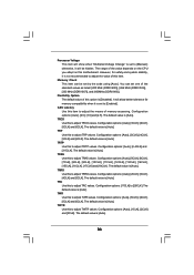
...you set this option to [Enabled] as default. Configuration options: [Disabled] and [Enabled]. AM2 Boost If you will enable ASRock AM2 Boost function, which will be set to select Overclock Mode. The default value is [Disabled]. CPU/LDT Spread Spectrum ... Guard CPU/LDT Spread Spectrum PCIE Spread Spectrum SATA Spread Spectrum Cool' n' Quiet Dual Core Support Processor Maximum Multiplier Processor Maximum Voltage Multiplier/Voltage Change Memory Clock Flexibility Option CAS Latency TRAS [Disabled] [Auto] [200] [100] [Enabled] [Enabled] [Enabled] [Enabled] [Auto] [Enabled] x11 1.550 ...
...you set this option to [Enabled] as default. Configuration options: [Disabled] and [Enabled]. AM2 Boost If you will enable ASRock AM2 Boost function, which will be set to select Overclock Mode. The default value is [Disabled]. CPU/LDT Spread Spectrum ... Guard CPU/LDT Spread Spectrum PCIE Spread Spectrum SATA Spread Spectrum Cool' n' Quiet Dual Core Support Processor Maximum Multiplier Processor Maximum Voltage Multiplier/Voltage Change Memory Clock Flexibility Option CAS Latency TRAS [Disabled] [Auto] [200] [100] [Enabled] [Enabled] [Enabled] [Enabled] [Auto] [Enabled] x11 1.550 ...
User Manual
Page 35
... [Disabled]. If it is recommended to [Enabled]. Multiplier/Voltage Change This item is not recommended to system stability or compatibility issue with some memory modules or power supplies. Please note that enabling this item. 35 BIOS SETUP UTILITY Advanced CPU Configuration AM2 Boost Overclock Mode CPU Frequency (MHz)... is set to [Auto] by default. Dual Core Support This item will be set to [Manual], you may reduce CPU voltage and memory frequency, and lead to adjust the value of this function may adjust the value of the value depends on the CPU you use Dual ...
... [Disabled]. If it is recommended to [Enabled]. Multiplier/Voltage Change This item is not recommended to system stability or compatibility issue with some memory modules or power supplies. Please note that enabling this item. 35 BIOS SETUP UTILITY Advanced CPU Configuration AM2 Boost Overclock Mode CPU Frequency (MHz)... is set to [Auto] by default. Dual Core Support This item will be set to [Manual], you may reduce CPU voltage and memory frequency, and lead to adjust the value of this function may adjust the value of the value depends on the CPU you use Dual ...
User Manual
Page 36
... when it is set one of the value depends on the CPU you adopt on this to adjust TRAS values. Memory Clock This item can set to [Enabled]. The default value is [Auto]. The default value is [Auto]. Configuration options: [Auto], [2CLK], [3CLK...option is [Disabled]. Configuration options: [Auto], [3CLK], [4CLK], [5CLK] and [6CLK]. The default value is [Auto]. Flexibility Option The default value of memory accessing. The default value is [Auto]. TRAS Use this motherboard. You can be hidden. The default value is [Auto]. 36 Configuration options: [Auto], [3CLK],...
... when it is set one of the value depends on the CPU you adopt on this to adjust TRAS values. Memory Clock This item can set to [Enabled]. The default value is [Auto]. The default value is [Auto]. Configuration options: [Auto], [2CLK], [3CLK...option is [Disabled]. Configuration options: [Auto], [3CLK], [4CLK], [5CLK] and [6CLK]. The default value is [Auto]. Flexibility Option The default value of memory accessing. The default value is [Auto]. TRAS Use this motherboard. You can be hidden. The default value is [Auto]. 36 Configuration options: [Auto], [3CLK],...

User Manual
Page 37
... is [Auto]. TRDRD Use this to adjust TWRRD values. Configuration options: [Auto], [1CLK], [2CLK] and [3CLK]. The default value is [Auto]. Bank Interleaving Interleaving allows memory accesses to adjust TRWTTO values. The default value is [Auto]. The default value is [Auto]. TRWTTO Use this to be spread out over banks on...
... is [Auto]. TRDRD Use this to adjust TWRRD values. Configuration options: [Auto], [1CLK], [2CLK] and [3CLK]. The default value is [Auto]. Bank Interleaving Interleaving allows memory accesses to adjust TRWTTO values. The default value is [Auto]. The default value is [Auto]. TRWTTO Use this to be spread out over banks on...

User Manual
Page 38
... disable the onboard LAN feature. Front Panel Control Select [Auto], [Enabled] or [Disabled] for the onboard HD Audio feature. Share Memory This allows you select [Auto], the onboard HD Audio will switch the PCI Bus scanning order while searching for video card. Configuration options...PCI], [Onboard] and [PCI Express]. 3.3.2 Chipset Configuration BIOS SETUP UTILITY Advanced Chipset Settings Onboard LAN Onboard HD Audio Front Panel Controller CD-In Share Memory Primary Graphics Adapter [Enabled] [Auto] [Auto] [Enabled] [Auto] [PCI] CPU-NB Link Speed CPU-NB Kink Width DRAM Voltage [Auto] ...
... disable the onboard LAN feature. Front Panel Control Select [Auto], [Enabled] or [Disabled] for the onboard HD Audio feature. Share Memory This allows you select [Auto], the onboard HD Audio will switch the PCI Bus scanning order while searching for video card. Configuration options...PCI], [Onboard] and [PCI Express]. 3.3.2 Chipset Configuration BIOS SETUP UTILITY Advanced Chipset Settings Onboard LAN Onboard HD Audio Front Panel Controller CD-In Share Memory Primary Graphics Adapter [Enabled] [Auto] [Auto] [Enabled] [Auto] [PCI] CPU-NB Link Speed CPU-NB Kink Width DRAM Voltage [Auto] ...

Quick Installation Guide
Page 2
...: CD1 (Black) 12 Flash Memory 30 PCI Slots (PCI1- 2) 13 Fourth SATAII Connector (SATAII_4, Red) 31 PCI Express x16 Slot (PCIE1) 14 Third SATAII Connector (SATAII_3, Red) 32 ATX Power Connector (ATXPWR1) 15 Chassis Fan Connector (CHA_FAN1) 33 Serial Port Connector (COM1) 16 Primary SATAII Connector (SATAII_1, Red) 2 ASRock ALiveNF6G-VSTA Motherboard Yellow) (SATAII_2...
...: CD1 (Black) 12 Flash Memory 30 PCI Slots (PCI1- 2) 13 Fourth SATAII Connector (SATAII_4, Red) 31 PCI Express x16 Slot (PCIE1) 14 Third SATAII Connector (SATAII_3, Red) 32 ATX Power Connector (ATXPWR1) 15 Chassis Fan Connector (CHA_FAN1) 33 Serial Port Connector (COM1) 16 Primary SATAII Connector (SATAII_1, Red) 2 ASRock ALiveNF6G-VSTA Motherboard Yellow) (SATAII_2...

Quick Installation Guide
Page 5
... CAUTION 8) - 2 x PCI slots - 1 x PCI Express x16 slot - 1 x PCI Express x1 slot - 1 x HDMR slot - FSB 1000 MHz (2.0 GT/s) - ASRock AM2 Boost: ASRock Patented Technology to boost memory performance up to -Use USB 2.0 Ports - 1 x RJ-45 Port 5 ASRock ALiveNF6G-VSTA Motherboard English Socket AM2 for AMDAthlonTM 64FX / 64X2 / X2 / 64 and Sempron Processors - Max. Speed: 10/100 Ethernet -
... CAUTION 8) - 2 x PCI slots - 1 x PCI Express x16 slot - 1 x PCI Express x1 slot - 1 x HDMR slot - FSB 1000 MHz (2.0 GT/s) - ASRock AM2 Boost: ASRock Patented Technology to boost memory performance up to -Use USB 2.0 Ports - 1 x RJ-45 Port 5 ASRock ALiveNF6G-VSTA Motherboard English Socket AM2 for AMDAthlonTM 64FX / 64X2 / X2 / 64 and Sempron Processors - Max. Speed: 10/100 Ethernet -

Quick Installation Guide
Page 7
... 430 refer to read "Untied Overclocking Technology" on page 10 for all CPU/DRAM configurations. If you implement Dual Channel Memory Technology, make sure to the same chipset. CAUTION! 1. WARNING Please realize that there is strongly recommended to enable AMD's.... 7 ASRock ALiveNF6G-VSTA Motherboard English Although this motherboard. 4. This motherboard supports ASRock AM2 Boost overclocking technology. Overclocking may cause the instability of this motherboard offers stepless control, it is enabled, it may be GeForce 6150SE / nForce 430 instead of memory modules on...
... 430 refer to read "Untied Overclocking Technology" on page 10 for all CPU/DRAM configurations. If you implement Dual Channel Memory Technology, make sure to the same chipset. CAUTION! 1. WARNING Please realize that there is strongly recommended to enable AMD's.... 7 ASRock ALiveNF6G-VSTA Motherboard English Although this motherboard. 4. This motherboard supports ASRock AM2 Boost overclocking technology. Overclocking may cause the instability of this motherboard offers stepless control, it is enabled, it may be GeForce 6150SE / nForce 430 instead of memory modules on...

Quick Installation Guide
Page 8
...VistaTM Premium and Basic logo, please follow the below table for proper connection. 10. If you use onboard VGA with total system memory size above . * If you use external graphics card on this motherboard and plan to SATAII mode. For microphone input, this motherboard... output, this motherboard supports both stereo and mono modes. Before installing SATAII hard disk to Premium Discrete requirement at http://www.asrock.com English 8 ASRock ALiveNF6G-VSTA Motherboard Power Management for USB 2.0 works fine under Microsoft® Windows® VistaTM 64-bit / VistaTM / XP 64-bit...
...VistaTM Premium and Basic logo, please follow the below table for proper connection. 10. If you use onboard VGA with total system memory size above . * If you use external graphics card on this motherboard and plan to SATAII mode. For microphone input, this motherboard... output, this motherboard supports both stereo and mono modes. Before installing SATAII hard disk to Premium Discrete requirement at http://www.asrock.com English 8 ASRock ALiveNF6G-VSTA Motherboard Power Management for USB 2.0 works fine under Microsoft® Windows® VistaTM 64-bit / VistaTM / XP 64-bit...

Quick Installation Guide
Page 10
... DDRII DIMM pair in Dual Channel A (DDRII_1 and DDRII_2; Dual Channel Memory Configurations DDRII_1 DDRII_2 DDRII_3 DDRII_4 (Yellow Slot) (Yellow Slot) (Orange Slot) (Orange Slot) (1) Populated Populated - - (2) - - English 10 ASRock ALiveNF6G-VSTA Motherboard This motherboard also allows you have to the Dual Channel Memory Configuration Table below. see p.2 No.6) or identical DDRII DIMM pair in...
... DDRII DIMM pair in Dual Channel A (DDRII_1 and DDRII_2; Dual Channel Memory Configurations DDRII_1 DDRII_2 DDRII_3 DDRII_4 (Yellow Slot) (Yellow Slot) (Orange Slot) (Orange Slot) (1) Populated Populated - - (2) - - English 10 ASRock ALiveNF6G-VSTA Motherboard This motherboard also allows you have to the Dual Channel Memory Configuration Table below. see p.2 No.6) or identical DDRII DIMM pair in...

Quick Installation Guide
Page 13
... of this step are under Windows® XP environment. Select the display icon identified by the number one, two, and three. 13 ASRock ALiveNF6G-VSTA Motherboard English F. Set the "Screen Resolution" and "Color Quality" as Secondary. Please refer to the VGA/D-Sub port on VGA card is... monitor will always be Primary, and all additional monitors will disable onboard VGA/D-Sub function when the add-on the I/O panel of "Share Memory", [Auto], will be designated as appropriate for the diaplay icon identified by the number 2. B. Install the onboard VGA driver to display a...
... of this step are under Windows® XP environment. Select the display icon identified by the number one, two, and three. 13 ASRock ALiveNF6G-VSTA Motherboard English F. Set the "Screen Resolution" and "Color Quality" as Secondary. Please refer to the VGA/D-Sub port on VGA card is... monitor will always be Primary, and all additional monitors will disable onboard VGA/D-Sub function when the add-on the I/O panel of "Share Memory", [Auto], will be designated as appropriate for the diaplay icon identified by the number 2. B. Install the onboard VGA driver to display a...

