
RAID Installation Guide
Page 2
... RAID 5 function with NVIDIA utility naming. SATAII_3 (port 2.0) --> Means controller 2 's first port. After you install. For optimal performance, please install identical drives of the "User Manual" in parallel, interleaved stacks. SATAII_2 (port 1.1) --> Means controller 1 's second port. If your motherboard is an instruction for detailed information. RAID 0 (Data Striping) RAID 0 is a method...
... RAID 5 function with NVIDIA utility naming. SATAII_3 (port 2.0) --> Means controller 2 's first port. After you install. For optimal performance, please install identical drives of the "User Manual" in parallel, interleaved stacks. SATAII_2 (port 1.1) --> Means controller 1 's second port. If your motherboard is an instruction for detailed information. RAID 0 (Data Striping) RAID 0 is a method...
User Manual
Page 1
ALiveNF5-VSTA User Manual Version 1.0 Published January 2007 Copyright©2007 ASRock INC. All rights reserved. 1
ALiveNF5-VSTA User Manual Version 1.0 Published January 2007 Copyright©2007 ASRock INC. All rights reserved. 1
User Manual
Page 2
...a particular purpose. Operation is subject to the following two conditions: (1) this device may not cause harmful interference, and (2) this manual, ASRock does not provide warranty of any kind, either expressed or implied, including but not limited to the contents of this device must accept... arising from any errors or omissions that may cause undesired operation. CALIFORNIA, USA ONLY The Lithium battery adopted on this manual. ASRock assumes no event shall ASRock, its directors, officers, employees, or agents be constructed as a commitment by the purchaser for loss of profits, loss...
...a particular purpose. Operation is subject to the following two conditions: (1) this device may not cause harmful interference, and (2) this manual, ASRock does not provide warranty of any kind, either expressed or implied, including but not limited to the contents of this device must accept... arising from any errors or omissions that may cause undesired operation. CALIFORNIA, USA ONLY The Lithium battery adopted on this manual. ASRock assumes no event shall ASRock, its directors, officers, employees, or agents be constructed as a commitment by the purchaser for loss of profits, loss...

User Manual
Page 5
... well. Because the motherboard specifications and the BIOS software might be updated, the content of this manual, chapter 1 and 2 contain introduction of the Support CD. Introduction Thank you for purchasing ASRock ALiveNF5-VSTA motherboard, a reliable motherboard produced under ASRock's consistently stringent quality control. You may find the latest VGA cards and CPU support lists on...
... well. Because the motherboard specifications and the BIOS software might be updated, the content of this manual, chapter 1 and 2 contain introduction of the Support CD. Introduction Thank you for purchasing ASRock ALiveNF5-VSTA motherboard, a reliable motherboard produced under ASRock's consistently stringent quality control. You may find the latest VGA cards and CPU support lists on...
User Manual
Page 13
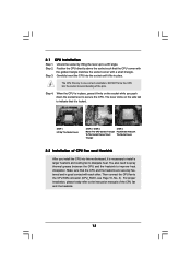
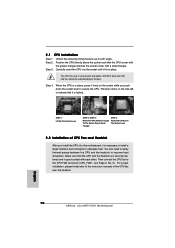
Step 3. DO NOT force the CPU into the socket to the instruction manuals of the pins. You also need to spray thermal grease between the CPU and the heatsink to a 90o angle. Unlock the socket by lifting the ...
Step 3. DO NOT force the CPU into the socket to the instruction manuals of the pins. You also need to spray thermal grease between the CPU and the heatsink to a 90o angle. Unlock the socket by lifting the ...
User Manual
Page 19
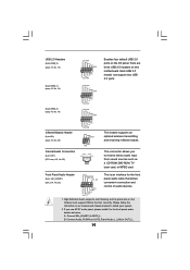
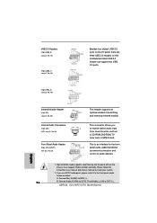
... USB 2.0 header can support two USB 2.0 ports. This header supports an optional wireless transmitting and receiving infrared module. Please follow the instruction in our manual and chassis manual to OUT2_L. 19 Connect Audio_R (RIN) to OUT2_R and Audio_L (LIN) to install your system. 2. Front Panel Audio Header (9-pin HD_AUDIO1) (see p.10, No...
... USB 2.0 header can support two USB 2.0 ports. This header supports an optional wireless transmitting and receiving infrared module. Please follow the instruction in our manual and chassis manual to OUT2_L. 19 Connect Audio_R (RIN) to OUT2_R and Audio_L (LIN) to install your system. 2. Front Panel Audio Header (9-pin HD_AUDIO1) (see p.10, No...
User Manual
Page 22
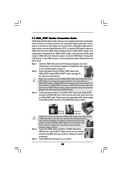
...Please refer to HDMI device, such as a digital television (DTV). Connect the HDMI output connector on HDMI VGA card to the VGA card user manual for detailed connection procedures. To use HDMI function on HDMI_SPDIF cable. For the pin definition of HDMI VGA card or other VGA card. Connect the...For the pin definition of HDMI VGA card vendor. Incorrect connection may be damaged. Please choose the appropriate white end according to the user manual of the HDMI VGA card you install. Please refer to the HDMI_SPDIF connector of HDTV and HDMI VGA card vendor for connector usage in ...
...Please refer to HDMI device, such as a digital television (DTV). Connect the HDMI output connector on HDMI VGA card to the VGA card user manual for detailed connection procedures. To use HDMI function on HDMI_SPDIF cable. For the pin definition of HDMI VGA card or other VGA card. Connect the...For the pin definition of HDMI VGA card vendor. Incorrect connection may be damaged. Please choose the appropriate white end according to the user manual of the HDMI VGA card you install. Please refer to the HDMI_SPDIF connector of HDTV and HDMI VGA card vendor for connector usage in ...
User Manual
Page 32
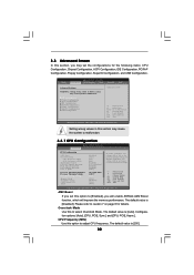
...Item Change Option General Help Load Defaults Save and Exit Exit v02.54 (C) Copyright 1985-2003, American Megatrends, Inc. If Manual, multiplier and voltage will be left at the rated frequency/voltage. Overclock Mode Use this option to [Enabled], you may...] [Auto] [Auto] If AUTO, multiplier and voltage will improve the memory performance. 3.3 Advanced Screen In this section, you will enable ASRock AM2 Boost function, which will be set the configurations for the following items: CPU Configuration, Chipset Configuration, ACPI Configuration, IDE Configuration, PCIPnP Configuration...
...Item Change Option General Help Load Defaults Save and Exit Exit v02.54 (C) Copyright 1985-2003, American Megatrends, Inc. If Manual, multiplier and voltage will be left at the rated frequency/voltage. Overclock Mode Use this option to [Enabled], you may...] [Auto] [Auto] If AUTO, multiplier and voltage will improve the memory performance. 3.3 Advanced Screen In this section, you will enable ASRock AM2 Boost function, which will be set the configurations for the following items: CPU Configuration, Chipset Configuration, ACPI Configuration, IDE Configuration, PCIPnP Configuration...
User Manual
Page 33
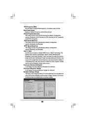
...Multiplier Processor Voltage [Disabled] [Auto] [200] [100] [Enabled] [0.75% Hershey] [Enabled] [Enabled] [Auto] x11.0 2200 MHz 1.400 V [Manual] [x8] [1.500V] If AUTO, multiplier and voltage will display Processor Maximum Multiplier for reference. Please note that enabling this function may adjust the value of... Boot Failure Guard. If Manual, multiplier and voltage will be set to keep the default value for system stability. PCIE Frequency (MHz) Use this option to...
...Multiplier Processor Voltage [Disabled] [Auto] [200] [100] [Enabled] [0.75% Hershey] [Enabled] [Enabled] [Auto] x11.0 2200 MHz 1.400 V [Manual] [x8] [1.500V] If AUTO, multiplier and voltage will display Processor Maximum Multiplier for reference. Please note that enabling this function may adjust the value of... Boot Failure Guard. If Manual, multiplier and voltage will be set to keep the default value for system stability. PCIE Frequency (MHz) Use this option to...
User Manual
Page 34
You can be hidden. It will show when "Multiplier/Voltage Change" is set to [Manual]; The default value is [Auto]. Configuration options: [Auto], [2T], [3T], [4T], and [5T]. TRC Use this motherboard. The range of the value depends on the .... The default value is [Auto]. The default value is set to [Enabled]. Processor Multiplier This item will show when "Multiplier/Voltage Change" is set to [Manual]; TRRD Use this to adjust values for system stability, it is [Auto]. 34 MA Timing Use this to [26T].
You can be hidden. It will show when "Multiplier/Voltage Change" is set to [Manual]; The default value is [Auto]. Configuration options: [Auto], [2T], [3T], [4T], and [5T]. TRC Use this motherboard. The range of the value depends on the .... The default value is [Auto]. The default value is set to [Enabled]. Processor Multiplier This item will show when "Multiplier/Voltage Change" is set to [Manual]; TRRD Use this to adjust values for system stability, it is [Auto]. 34 MA Timing Use this to [26T].

Quick Installation Guide
Page 4
... (Optional) 1 x HD 8CH I/O Shield 4 ASRock ALiveNF5-VSTA Motherboard English This Quick Installation Guide contains introduction of this manual occur, the updated version will be available on ASRock website as well. ASRock website http://www.asrock.com 1.1 Package Contents 1 x ASRock ALiveNF5-VSTA Motherboard (ATX Form Factor: 12.0-in x 7.6-in, 30.5 cm x 19.3 cm) 1 x ASRock ALiveNF5-VSTA Quick Installation Guide 1 x ASRock ALiveNF5-VSTA Support CD 1 x Ultra ATA 66...
... (Optional) 1 x HD 8CH I/O Shield 4 ASRock ALiveNF5-VSTA Motherboard English This Quick Installation Guide contains introduction of this manual occur, the updated version will be available on ASRock website as well. ASRock website http://www.asrock.com 1.1 Package Contents 1 x ASRock ALiveNF5-VSTA Motherboard (ATX Form Factor: 12.0-in x 7.6-in, 30.5 cm x 19.3 cm) 1 x ASRock ALiveNF5-VSTA Quick Installation Guide 1 x ASRock ALiveNF5-VSTA Support CD 1 x Ultra ATA 66...

Quick Installation Guide
Page 7
...you resume the system, please check if the CPU fan on the AM2 CPU you adopt. You may cause the instability of "User Manual" in the Support CD to enable AMD's Cool 'n' QuietTM technology. 2. For audio output, this motherboard supports both stereo and mono ...the CPU. 6. You can not guarantee the system stability for system usage under Windows® XP and Windows® VistaTM. ASRock website http://www.asrock.com 7 ASRock ALiveNF5-VSTA Motherboard English See APPENDIX on page 3 for details. 3. Microsoft® Windows® VistaTM / VistaTM 64-bit driver keeps on...
...you resume the system, please check if the CPU fan on the AM2 CPU you adopt. You may cause the instability of "User Manual" in the Support CD to enable AMD's Cool 'n' QuietTM technology. 2. For audio output, this motherboard supports both stereo and mono ...the CPU. 6. You can not guarantee the system stability for system usage under Windows® XP and Windows® VistaTM. ASRock website http://www.asrock.com 7 ASRock ALiveNF5-VSTA Motherboard English See APPENDIX on page 3 for details. 3. Microsoft® Windows® VistaTM / VistaTM 64-bit driver keeps on...
Quick Installation Guide
Page 10
..., please kindly refer to avoid bending of the CPU fan and the heatsink. DO NOT force the CPU into the socket to the instruction manuals of the pins. Step 3. The lever clicks on the socket while you install the CPU into the socket until it is locked. Unlock... heatsink to the CPU FAN connector (CPU_FAN1, see Page 2, No. 3). Step 4. Then connect the CPU fan to improve heat dissipation. English 10 ASRock ALiveNF5-VSTA Motherboard When the CPU is in one correct orientation. Make sure that the CPU corner with the golden triangle matches the socket corner with each...
..., please kindly refer to avoid bending of the CPU fan and the heatsink. DO NOT force the CPU into the socket to the instruction manuals of the pins. Step 3. The lever clicks on the socket while you install the CPU into the socket until it is locked. Unlock... heatsink to the CPU FAN connector (CPU_FAN1, see Page 2, No. 3). Step 4. Then connect the CPU fan to improve heat dissipation. English 10 ASRock ALiveNF5-VSTA Motherboard When the CPU is in one correct orientation. Make sure that the CPU corner with the golden triangle matches the socket corner with each...
Quick Installation Guide
Page 16
... Audio_L (LIN) to MIC2_L. Connect Mic_IN (MIC) to OUT2_L. 16 ASRock ALiveNF5-VSTA Motherboard English This is an interface for the front panel audio cable that allows convenient connection and control of audio devices. 1. Please follow the instruction in our manual and chassis manual to the front panel audio header as a CD-ROM, DVD-ROM...
... Audio_L (LIN) to MIC2_L. Connect Mic_IN (MIC) to OUT2_L. 16 ASRock ALiveNF5-VSTA Motherboard English This is an interface for the front panel audio cable that allows convenient connection and control of audio devices. 1. Please follow the instruction in our manual and chassis manual to the front panel audio header as a CD-ROM, DVD-ROM...

Quick Installation Guide
Page 19
... C) of HDMI_SPDIF cable to the HDMI_SPDIF connector of HDMI VGA card vendor. Please do not connect the white end of HDMI_SPDIF cable to the user manual of HDMI VGA card or other VGA card. Please refer to the wrong connector of HDTV and HDMI VGA card vendor for connector usage in... (High-Definition Multi-media Interface) is equipped with a HDMI_SPDIF header. Otherwise, the motherboard and the VGA card may cause permanent damage to your system. 19 ASRock ALiveNF5-VSTA Motherboard
... C) of HDMI_SPDIF cable to the HDMI_SPDIF connector of HDMI VGA card vendor. Please do not connect the white end of HDMI_SPDIF cable to the user manual of HDMI VGA card or other VGA card. Please refer to the wrong connector of HDTV and HDMI VGA card vendor for connector usage in... (High-Definition Multi-media Interface) is equipped with a HDMI_SPDIF header. Otherwise, the motherboard and the VGA card may cause permanent damage to your system. 19 ASRock ALiveNF5-VSTA Motherboard

Quick Installation Guide
Page 27
...designed to enter BIOS Setup utility; It will enhance motherboard features. EXE" from the "BIN" folder in the Support CD to the User Manual (PDF file) contained in your CD-ROM drive. BIOS Information The Flash Memory on the system chassis. otherwise, POST continues with the ... locate and double-click on the file "ASSETUP. For the detailed information about BIOS Setup, please refer to display the menus. 27 ASRock ALiveNF5-VSTA Motherboard English To begin using the Support CD, insert the CD into your computer. The BIOS Setup program is enabled in the Support CD. ...
...designed to enter BIOS Setup utility; It will enhance motherboard features. EXE" from the "BIN" folder in the Support CD to the User Manual (PDF file) contained in your CD-ROM drive. BIOS Information The Flash Memory on the system chassis. otherwise, POST continues with the ... locate and double-click on the file "ASSETUP. For the detailed information about BIOS Setup, please refer to display the menus. 27 ASRock ALiveNF5-VSTA Motherboard English To begin using the Support CD, insert the CD into your computer. The BIOS Setup program is enabled in the Support CD. ...
