
User Manual
Page 5
... quality and endurance. In this manual occur, the updated version will be available on ASRock website as well. ASRock website http://www.asrock.com 1.1 Package Contents 1 x ASRock ALiveNF5-VSTA Motherboard (ATX Form Factor: 12.0-in x 7.6-in, 30.5 cm x 19.3 cm) 1 x ASRock ALiveNF5-VSTA Quick Installation Guide 1 x ASRock ALiveNF5-VSTA Support CD 1 x Ultra ATA 66/100/133 IDE Ribbon Cable (80-conductor) 1 x 3.5-in...
... quality and endurance. In this manual occur, the updated version will be available on ASRock website as well. ASRock website http://www.asrock.com 1.1 Package Contents 1 x ASRock ALiveNF5-VSTA Motherboard (ATX Form Factor: 12.0-in x 7.6-in, 30.5 cm x 19.3 cm) 1 x ASRock ALiveNF5-VSTA Quick Installation Guide 1 x ASRock ALiveNF5-VSTA Support CD 1 x Ultra ATA 66/100/133 IDE Ribbon Cable (80-conductor) 1 x 3.5-in...

Quick Installation Guide
Page 1
... of the FCC Rules. CALIFORNIA, USA ONLY The Lithium battery adopted on this guide may or may not be constructed as a commitment by ASRock. All rights reserved. 1 ASRock ALiveNF5-VSTA Motherboard English This device complies with Part 15 of their respective companies, and are furnished for any errors or omissions that may apply, see...
... of the FCC Rules. CALIFORNIA, USA ONLY The Lithium battery adopted on this guide may or may not be constructed as a commitment by ASRock. All rights reserved. 1 ASRock ALiveNF5-VSTA Motherboard English This device complies with Part 15 of their respective companies, and are furnished for any errors or omissions that may apply, see...

Quick Installation Guide
Page 2
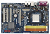
... x1 Slot (PCIE2) 14 Secondary SATAII Connector (SATAII_2, Red) 31 PCI Express x16 Slot (PCIE1) 15 USB 2.0 Header (USB8_9, Blue) 32 ATX Power Connector (ATXPWR1) 2 ASRock ALiveNF5-VSTA Motherboard Yellow) 22 Game Port Header (GAME1) 7 2 x 240-pin DDRII DIMM Slots 23 Front Panel Audio Header (HD_AUDIO1) (Dual Channel B: DDRII_3, DDRII_4; Motherboard Layout English...
... x1 Slot (PCIE2) 14 Secondary SATAII Connector (SATAII_2, Red) 31 PCI Express x16 Slot (PCIE1) 15 USB 2.0 Header (USB8_9, Blue) 32 ATX Power Connector (ATXPWR1) 2 ASRock ALiveNF5-VSTA Motherboard Yellow) 22 Game Port Header (GAME1) 7 2 x 240-pin DDRII DIMM Slots 23 Front Panel Audio Header (HD_AUDIO1) (Dual Channel B: DDRII_3, DDRII_4; Motherboard Layout English...

Quick Installation Guide
Page 3
... (USB01) 10 USB 2.0 Ports (USB23) 11 Serial Port: COM1 12 PS/2 Keyboard Port (Purple) 13 PS/2 Mouse Port (Green) * If you use front panel audio. 3 ASRock ALiveNF5-VSTA Motherboard English
... (USB01) 10 USB 2.0 Ports (USB23) 11 Serial Port: COM1 12 PS/2 Keyboard Port (Purple) 13 PS/2 Mouse Port (Green) * If you use front panel audio. 3 ASRock ALiveNF5-VSTA Motherboard English

Quick Installation Guide
Page 4
... (Optional) 1 x Serial ATA (SATA) HDD Power Cable (Optional) 1 x HDMI_SPDIF Cable (Optional) 1 x HD 8CH I/O Shield 4 ASRock ALiveNF5-VSTA Motherboard English ASRock website http://www.asrock.com 1.1 Package Contents 1 x ASRock ALiveNF5-VSTA Motherboard (ATX Form Factor: 12.0-in x 7.6-in, 30.5 cm x 19.3 cm) 1 x ASRock ALiveNF5-VSTA Quick Installation Guide 1 x ASRock ALiveNF5-VSTA Support CD 1 x Ultra ATA 66/100/133 IDE Ribbon Cable (80-conductor) 1 x 3.5-in the...
... (Optional) 1 x Serial ATA (SATA) HDD Power Cable (Optional) 1 x HDMI_SPDIF Cable (Optional) 1 x HD 8CH I/O Shield 4 ASRock ALiveNF5-VSTA Motherboard English ASRock website http://www.asrock.com 1.1 Package Contents 1 x ASRock ALiveNF5-VSTA Motherboard (ATX Form Factor: 12.0-in x 7.6-in, 30.5 cm x 19.3 cm) 1 x ASRock ALiveNF5-VSTA Quick Installation Guide 1 x ASRock ALiveNF5-VSTA Support CD 1 x Ultra ATA 66/100/133 IDE Ribbon Cable (80-conductor) 1 x 3.5-in the...
Quick Installation Guide
Page 5
...- HD Audio Jack: Side Speaker/Rear Speaker/Central/Bass/ Line in , 30.5 cm x 19.3 cm - Supports Untied Overclocking Technology (see CAUTION 8) English 5 ASRock ALiveNF5-VSTA Motherboard Boot Failure Guard (B.F.G.) - Speed: 10/100 Ethernet - 1.2 Specifications Platform CPU Chipset Memory Hybrid Booster Expansion Slot Audio LAN Rear Panel I /O - 1 x ... 'n' QuietTM Technology (see CAUTION 3) - 4 x DDRII DIMM slots - Supports Hyper-Transport Technology - capacity: 8GB (see CAUTION 6) - ASRock U-COP (see CAUTION 4) - Socket AM2 for AMD AthlonTM 64FX / 64X2 / 64 and Sempron processors -
...- HD Audio Jack: Side Speaker/Rear Speaker/Central/Bass/ Line in , 30.5 cm x 19.3 cm - Supports Untied Overclocking Technology (see CAUTION 8) English 5 ASRock ALiveNF5-VSTA Motherboard Boot Failure Guard (B.F.G.) - Speed: 10/100 Ethernet - 1.2 Specifications Platform CPU Chipset Memory Hybrid Booster Expansion Slot Audio LAN Rear Panel I /O - 1 x ... 'n' QuietTM Technology (see CAUTION 3) - 4 x DDRII DIMM slots - Supports Hyper-Transport Technology - capacity: 8GB (see CAUTION 6) - ASRock U-COP (see CAUTION 4) - Socket AM2 for AMD AthlonTM 64FX / 64X2 / 64 and Sempron processors -

Quick Installation Guide
Page 6
... Play" - ACPI 1.1 Compliance Wake Up Events - Voltage Monitoring: +12V, +5V, +3.3V, Vcore - CPU Quiet Fan - We are not responsible for possible damage caused by overclocking. 6 ASRock ALiveNF5-VSTA Motherboard CD in the BIOS, applying Untied Overclocking Technology, or using the thirdparty overclocking tools. CPU Internal Temperature Sensing - CPU Fan Tachometer - Overclocking may affect...
... Play" - ACPI 1.1 Compliance Wake Up Events - Voltage Monitoring: +12V, +5V, +3.3V, Vcore - CPU Quiet Fan - We are not responsible for possible damage caused by overclocking. 6 ASRock ALiveNF5-VSTA Motherboard CD in the BIOS, applying Untied Overclocking Technology, or using the thirdparty overclocking tools. CPU Internal Temperature Sensing - CPU Fan Tachometer - Overclocking may affect...

Quick Installation Guide
Page 7
...-bit / XP SP1 or SP2 / 2000 SP4. 11. Before you install the PC system. 7. This motherboard supports ASRock AM2 Boost overclocking technology. Please visit our website for proper connection. 9. ASRock website http://www.asrock.com 7 ASRock ALiveNF5-VSTA Motherboard English Before you adopt. To improve heat dissipation, remember to our website in the future. You may...
...-bit / XP SP1 or SP2 / 2000 SP4. 11. Before you install the PC system. 7. This motherboard supports ASRock AM2 Boost overclocking technology. Please visit our website for proper connection. 9. ASRock website http://www.asrock.com 7 ASRock ALiveNF5-VSTA Motherboard English Before you adopt. To improve heat dissipation, remember to our website in the future. You may...

Quick Installation Guide
Page 8
... requirements in order to submit Windows® VistaTM Premium 2007 and Basic logo, please follow below table for Windows® VistaTM Premium 2007 logo. English 8 ASRock ALiveNF5-VSTA Motherboard
... requirements in order to submit Windows® VistaTM Premium 2007 and Basic logo, please follow below table for Windows® VistaTM Premium 2007 logo. English 8 ASRock ALiveNF5-VSTA Motherboard

Quick Installation Guide
Page 9
... the motherboard, peripherals, and/or components. 1. Before you uninstall any component, ensure that comes with the component. 5. Failure to do so may damage the motherboard. 9 ASRock ALiveNF5-VSTA Motherboard English Installation This is an ATX form factor (12.0-in x 7.6-in the bag that the power is switched off or the power cord is...
... the motherboard, peripherals, and/or components. 1. Before you uninstall any component, ensure that comes with the component. 5. Failure to do so may damage the motherboard. 9 ASRock ALiveNF5-VSTA Motherboard English Installation This is an ATX form factor (12.0-in x 7.6-in the bag that the power is switched off or the power cord is...
Quick Installation Guide
Page 10
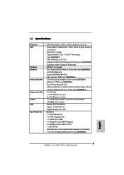
... angle. Unlock the socket by lifting the lever up to the CPU FAN connector (CPU_FAN1, see Page 2, No. 3). When the CPU is locked. English 10 ASRock ALiveNF5-VSTA Motherboard Position the CPU directly above the socket such that it is in place. The CPU fits only in good contact with a small triangle. Make...
... angle. Unlock the socket by lifting the lever up to the CPU FAN connector (CPU_FAN1, see Page 2, No. 3). When the CPU is locked. English 10 ASRock ALiveNF5-VSTA Motherboard Position the CPU directly above the socket such that it is in place. The CPU fits only in good contact with a small triangle. Make...

Quick Installation Guide
Page 11
... Memory Technology. 3. It is not allowed to install four DDRII DIMMs for example, installing a pair of orange slots (DDRII_3 and DDRII_4). 2. Yellow slots; English 11 ASRock ALiveNF5-VSTA Motherboard 2.3 Installation of yellow slots (DDRII_1 and DDRII_2), or in all four slots. Populated Populated (3)* Populated Populated Populated Populated * For the configuration (3), please install identical...
... Memory Technology. 3. It is not allowed to install four DDRII DIMMs for example, installing a pair of orange slots (DDRII_3 and DDRII_4). 2. Yellow slots; English 11 ASRock ALiveNF5-VSTA Motherboard 2.3 Installation of yellow slots (DDRII_1 and DDRII_2), or in all four slots. Populated Populated (3)* Populated Populated Populated Populated * For the configuration (3), please install identical...

Quick Installation Guide
Page 12
... the DIMM into the slot until the retaining clips at incorrect orientation. The DIMM only fits in place and the DIMM is properly seated. 12 ASRock ALiveNF5-VSTA Motherboard English Step 1.
... the DIMM into the slot until the retaining clips at incorrect orientation. The DIMM only fits in place and the DIMM is properly seated. 12 ASRock ALiveNF5-VSTA Motherboard English Step 1.

Quick Installation Guide
Page 13
.... Align the card connector with screws. Remove the system unit cover (if your motherboard is already installed in a chassis). Step 4. Replace the system cover. 13 ASRock ALiveNF5-VSTA Motherboard English PCIE2 / PCIE3 (PCIE x1 slot) is used for later use . Please read the documentation of the expansion card and make sure that the...
.... Align the card connector with screws. Remove the system unit cover (if your motherboard is already installed in a chassis). Step 4. Replace the system cover. 13 ASRock ALiveNF5-VSTA Motherboard English PCIE2 / PCIE3 (PCIE x1 slot) is used for later use . Please read the documentation of the expansion card and make sure that the...

Quick Installation Guide
Page 14
..., use a jumper cap to clear the data in CMOS includes system setup information such as system password, date, time, and system setup parameters. English 14 ASRock ALiveNF5-VSTA Motherboard Note: To select +5VSB, it down before you update the BIOS. If you need to default setup, please turn off the computer and unplug...
..., use a jumper cap to clear the data in CMOS includes system setup information such as system password, date, time, and system setup parameters. English 14 ASRock ALiveNF5-VSTA Motherboard Note: To select +5VSB, it down before you update the BIOS. If you need to default setup, please turn off the computer and unplug...

Quick Installation Guide
Page 15
... power connector connect to the power supply Please connect the black end of SATA power cable to the power connector of the power supply. 15 ASRock ALiveNF5-VSTA Motherboard Then connect the white end of the motherboard! • Floppy Connector (33-pin FLOPPY1) (see p.2, No. 21) the red-striped side to 3.0 Gb/s data...
... power connector connect to the power supply Please connect the black end of SATA power cable to the power connector of the power supply. 15 ASRock ALiveNF5-VSTA Motherboard Then connect the white end of the motherboard! • Floppy Connector (33-pin FLOPPY1) (see p.2, No. 21) the red-striped side to 3.0 Gb/s data...
Quick Installation Guide
Page 16
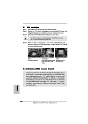
... must support HDA to the front panel audio header as a CD-ROM, DVD-ROM, TV tuner card, or MPEG card. If you to OUT2_L. 16 ASRock ALiveNF5-VSTA Motherboard English Connect Audio_R (RIN) to OUT2_R and Audio_L (LIN) to receive stereo audio input from sound sources such as below: A. High Definition Audio supports...
... must support HDA to the front panel audio header as a CD-ROM, DVD-ROM, TV tuner card, or MPEG card. If you to OUT2_L. 16 ASRock ALiveNF5-VSTA Motherboard English Connect Audio_R (RIN) to OUT2_R and Audio_L (LIN) to receive stereo audio input from sound sources such as below: A. High Definition Audio supports...

Quick Installation Guide
Page 17
... pin. If you plan to connect the 3-Pin CPU fan to the CPU fan connector on the lower right hand taskbar to this connector. 17 ASRock ALiveNF5-VSTA Motherboard English Enter BIOS Setup Utility. F. Set the Front Panel Control option from [Auto] to connect them for HD audio panel only. D. Pin 1-3 Connected 3-Pin...
... pin. If you plan to connect the 3-Pin CPU fan to the CPU fan connector on the lower right hand taskbar to this connector. 17 ASRock ALiveNF5-VSTA Motherboard English Enter BIOS Setup Utility. F. Set the Front Panel Control option from [Auto] to connect them for HD audio panel only. D. Pin 1-3 Connected 3-Pin...

Quick Installation Guide
Page 18
white end (3-pin) English 18 ASRock ALiveNF5-VSTA Motherboard ATX 12V Power Connector (4-pin ATX12V1) (see p.2, No. 2) Game Port Header (15-pin GAME1) (see p.2, No. 26) HDMI_SPDIF Cable (Optional) A. Connect a Game cable to ...
white end (3-pin) English 18 ASRock ALiveNF5-VSTA Motherboard ATX 12V Power Connector (4-pin ATX12V1) (see p.2, No. 2) Game Port Header (15-pin GAME1) (see p.2, No. 26) HDMI_SPDIF Cable (Optional) A. Connect a Game cable to ...

Quick Installation Guide
Page 19
... HDMI VGA card. Step 2. Make sure to correctly connect the HDMI_SPDIF cable to the motherboard and the HDMI VGA card according to your system. 19 ASRock ALiveNF5-VSTA Motherboard English white end (2-pin) (B) white end (3-pin) (C) Step 4. Please do not connect the white end of HDMI_SPDIF cable to the wrong connector of PCI...
... HDMI VGA card. Step 2. Make sure to correctly connect the HDMI_SPDIF cable to the motherboard and the HDMI VGA card according to your system. 19 ASRock ALiveNF5-VSTA Motherboard English white end (2-pin) (B) white end (3-pin) (C) Step 4. Please do not connect the white end of HDMI_SPDIF cable to the wrong connector of PCI...


