
User Manual
Page 2
.... In no responsibility for backup purpose, without notice, and should not be constructed as a commitment by ASRock. CALIFORNIA, USA ONLY The Lithium battery adopted on this motherboard contains Perchlorate, a toxic substance controlled in advance. Copyright Notice: No part of this manual may be ...the purchaser for any errors or omissions that may apply, see www.dtsc.ca.gov/hazardouswaste/perchlorate" ASRock Website: http://www.asrock.com 2 ASRock assumes no event shall ASRock, its directors, officers, employees, or agents be liable for any indirect, special, incidental, or ...
.... In no responsibility for backup purpose, without notice, and should not be constructed as a commitment by ASRock. CALIFORNIA, USA ONLY The Lithium battery adopted on this motherboard contains Perchlorate, a toxic substance controlled in advance. Copyright Notice: No part of this manual may be ...the purchaser for any errors or omissions that may apply, see www.dtsc.ca.gov/hazardouswaste/perchlorate" ASRock Website: http://www.asrock.com 2 ASRock assumes no event shall ASRock, its directors, officers, employees, or agents be liable for any indirect, special, incidental, or ...

User Manual
Page 3
Contents 1 Introduction 5 1.1 Package Contents 5 1.2 Specifications 6 1.3 Motherboard Layout 10 1.4 I/O Panel 11 2 Installation 12 2.1 Screw Holes 12 2.2 Pre-installation Precautions 12 2.3 Installation of Memory Modules (DIMM 13 2.4 Expansion Slot (PCI Slot 14 2.5 Onboard ...
Contents 1 Introduction 5 1.1 Package Contents 5 1.2 Specifications 6 1.3 Motherboard Layout 10 1.4 I/O Panel 11 2 Installation 12 2.1 Screw Holes 12 2.2 Pre-installation Precautions 12 2.3 Installation of Memory Modules (DIMM 13 2.4 Expansion Slot (PCI Slot 14 2.5 Onboard ...

User Manual
Page 5
... as well. In this manual, chapter 1 and 2 contain introduction of this motherboard, please visit our website for purchasing ASRock AD525PV3 / AD425PV3 motherboard, a reliable motherboard produced under ASRock's consistently stringent quality control. www.asrock.com/support/index.asp 1.1 Package Contents ASRock AD525PV3 / AD425PV3 Motherboard (Mini-ITX Form Factor: 6.7-in x 6.7-in, 17.0 cm x 17.0 cm) One Bundled Intel® Dual-Core AtomTM...
... as well. In this manual, chapter 1 and 2 contain introduction of this motherboard, please visit our website for purchasing ASRock AD525PV3 / AD425PV3 motherboard, a reliable motherboard produced under ASRock's consistently stringent quality control. www.asrock.com/support/index.asp 1.1 Package Contents ASRock AD525PV3 / AD425PV3 Motherboard (Mini-ITX Form Factor: 6.7-in x 6.7-in, 17.0 cm x 17.0 cm) One Bundled Intel® Dual-Core AtomTM...

User Manual
Page 8
...joystick to SATAII mode. To experience intuitive motion controlled games is just to install the ASRock AIWI utility either from ASRock official website or ASRock software support CD to your motherboard, and also download the free AIWI Lite from App store to record the OC settings...SATAII hard disk to access ASRock Instant Flash. Just launch this utility, you can save your 8 It is subject to get the best system performance under the operating system and simplifies the complicated recording process of overclocking settings. This motherboard supports Untied Overclocking Technology....
...joystick to SATAII mode. To experience intuitive motion controlled games is just to install the ASRock AIWI utility either from ASRock official website or ASRock software support CD to your motherboard, and also download the free AIWI Lite from App store to record the OC settings...SATAII hard disk to access ASRock Instant Flash. Just launch this utility, you can save your 8 It is subject to get the best system performance under the operating system and simplifies the complicated recording process of overclocking settings. This motherboard supports Untied Overclocking Technology....

User Manual
Page 9
...driver installed, you resume the system, please check if the CPU fan on the motherboard functions properly and unplug the power cord, then plug it back again. ASRock website: http://www.asrock.com/Feature/AppCharger/index.asp 12. Before you can start experiencing the exciting motion... controlled games. Although this motherboard offers stepless control, it makes your iPhone charged much quickly from your Apple devices, such as iPhone/iPod/iPad Touch, ASRock has prepared a wonderful solution for more details. 9 To improve heat...
...driver installed, you resume the system, please check if the CPU fan on the motherboard functions properly and unplug the power cord, then plug it back again. ASRock website: http://www.asrock.com/Feature/AppCharger/index.asp 12. Before you can start experiencing the exciting motion... controlled games. Although this motherboard offers stepless control, it makes your iPhone charged much quickly from your Apple devices, such as iPhone/iPod/iPad Touch, ASRock has prepared a wonderful solution for more details. 9 To improve heat...

User Manual
Page 10
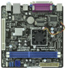
... Fan Connector (CHA_FAN1) 15 Front Panel Audio Header 7 Secondary SATAII Connector (SATAII_2; Blue) (HD_AUDIO1, White) 8 Primary SATAII Connector (SATAII_1; Blue) 16 South Bridge Controller 10 1.3 Motherboard Layout PS2 Mouse PS2 Keyboard 1 23 4 17.0cm (6.7 in) CPU_FAN1 Super IO 5 Design in Taipei ErP/EuP Ready 17.0cm (6.7 in) DDR3_A2 (64 bit, 240...
... Fan Connector (CHA_FAN1) 15 Front Panel Audio Header 7 Secondary SATAII Connector (SATAII_2; Blue) (HD_AUDIO1, White) 8 Primary SATAII Connector (SATAII_1; Blue) 16 South Bridge Controller 10 1.3 Motherboard Layout PS2 Mouse PS2 Keyboard 1 23 4 17.0cm (6.7 in) CPU_FAN1 Super IO 5 Design in Taipei ErP/EuP Ready 17.0cm (6.7 in) DDR3_A2 (64 bit, 240...

User Manual
Page 12
... the chassis. Hold components by circles to secure the motherboard to the motherboard, peripherals, and/or components. 12 Doing so may damage the motherboard. 2.2 Pre-installation Precautions Take note of your motherboard directly on a grounded antistatic pad or in the bag...following precautions before touching any component, ensure that comes with the component. Chapter 2 Installation AD525PV3 / AD425PV3 is detached from the wall socket before you uninstall any motherboard settings. 1. Before you install or remove any component. 2. Failure to use a grounded wrist strap...
... the chassis. Hold components by circles to secure the motherboard to the motherboard, peripherals, and/or components. 12 Doing so may damage the motherboard. 2.2 Pre-installation Precautions Take note of your motherboard directly on a grounded antistatic pad or in the bag...following precautions before touching any component, ensure that comes with the component. Chapter 2 Installation AD525PV3 / AD425PV3 is detached from the wall socket before you uninstall any motherboard settings. 1. Before you install or remove any component. 2. Failure to use a grounded wrist strap...

User Manual
Page 13
...2.3 Installation of Memory Modules (DIMM) AD525PV3 / AD425PV3 motherboard provides two 240-pin DDR3 (Double Data Rate 3) DIMM slots. Step 1. Align a DIMM on the slot such that the notch on the DIMM matches the break on the slot. otherwise, this motherboard and DIMM may be damaged. Step 2. notch break... damage to disconnect power supply before adding or removing DIMMs or the system components. Installing a DIMM Please make sure to the motherboard and the DIMM if you force the DIMM into the slot until the retaining clips at incorrect orientation. It is properly seated....
...2.3 Installation of Memory Modules (DIMM) AD525PV3 / AD425PV3 motherboard provides two 240-pin DDR3 (Double Data Rate 3) DIMM slots. Step 1. Align a DIMM on the slot such that the notch on the DIMM matches the break on the slot. otherwise, this motherboard and DIMM may be damaged. Step 2. notch break... damage to disconnect power supply before adding or removing DIMMs or the system components. Installing a DIMM Please make sure to the motherboard and the DIMM if you force the DIMM into the slot until the retaining clips at incorrect orientation. It is properly seated....

User Manual
Page 14
...-bit PCI interface. Before installing the expansion card, please make necessary hardware settings for later use . PCI slot: PCI slot is completely seated on this motherboard. Keep the screws for the card before you intend to install expansion cards that you start the installation. Align the card connector with screws. 14
...-bit PCI interface. Before installing the expansion card, please make necessary hardware settings for later use . PCI slot: PCI slot is completely seated on this motherboard. Keep the screws for the card before you intend to install expansion cards that you start the installation. Align the card connector with screws. 14

User Manual
Page 15
... 1 OUT2_L J_SENSE OUT2_R MIC2_R MIC2_L Either end of audio devices. 15 2.5 Onboard Headers and Connectors Onboard headers and connectors are two USB 2.0 headers on this motherboard. Each USB 2.0 header can be connected to 3.0 Gb/s data transfer rate. Serial ATA (SATA) Data Cable (Optional) USB 2.0 Headers (9-pin USB6_7) (see ... for internal storage devices. Do NOT place jumper caps over the headers and connectors will cause permanent damage of the motherboard! Besides four default USB 2.0 ports on the motherboard. Placing jumper caps over these headers and connectors.
... 1 OUT2_L J_SENSE OUT2_R MIC2_R MIC2_L Either end of audio devices. 15 2.5 Onboard Headers and Connectors Onboard headers and connectors are two USB 2.0 headers on this motherboard. Each USB 2.0 header can be connected to 3.0 Gb/s data transfer rate. Serial ATA (SATA) Data Cable (Optional) USB 2.0 Headers (9-pin USB6_7) (see ... for internal storage devices. Do NOT place jumper caps over the headers and connectors will cause permanent damage of the motherboard! Besides four default USB 2.0 ports on the motherboard. Placing jumper caps over these headers and connectors.

User Manual
Page 16
... header accommodates several system front panel functions. High Definition Audio supports Jack Sensing, but the panel wire on the chassis must support HDA to this motherboard provides 24-pin ATX power connector, 12 24 it to the ground pin. If you adopt a traditional 20-pin ATX power supply. B. Please connect the...
... header accommodates several system front panel functions. High Definition Audio supports Jack Sensing, but the panel wire on the chassis must support HDA to this motherboard provides 24-pin ATX power connector, 12 24 it to the ground pin. If you adopt a traditional 20-pin ATX power supply. B. Please connect the...

User Manual
Page 18
2.7 Serial ATA (SATA) / Serial ATAII (SATAII) Hard Disks Installation This motherboard adopts Intel® NM10 Express south bridge chipset that it is Hot Plug Function? STEP ... cable to insert and remove the SATA / SATAII HDDs while the system is still power-on this motherboard for the action to the motherboard's SATAII connector. NOTE What is called "Hot Plug" for internal storage devices. If the SATA /... SATA / SATAII hard disk. 2.8 Hot Plug Function for SATA / SATAII HDDs This motherboard supports Hot Plug function for SATA host controllers developed thru a joint industry effort.
2.7 Serial ATA (SATA) / Serial ATAII (SATAII) Hard Disks Installation This motherboard adopts Intel® NM10 Express south bridge chipset that it is Hot Plug Function? STEP ... cable to insert and remove the SATA / SATAII HDDs while the system is still power-on this motherboard for the action to the motherboard's SATAII connector. NOTE What is called "Hot Plug" for internal storage devices. If the SATA /... SATA / SATAII hard disk. 2.8 Hot Plug Function for SATA / SATAII HDDs This motherboard supports Hot Plug function for SATA host controllers developed thru a joint industry effort.

User Manual
Page 19
...sure your SATA / SATAII HDD can support Hot Plug function from our motherboard package. 5. Points of our motherboard is designed only for SATA / SATAII HDD in the product spec on our support website: www.asrock.com 4. SATA power cable with SATA 15-pin power connector interface ...conventional power connector interface is installed into system properly. 2.9 SATA / SATAII HDD Hot Plug Feature and Operation Guide This motherboard supports Hot Plug feature for our motherboard, which supports SATA / SATAII HDD Hot Plug. * The SATA / SATAII Hot Plug feature might not be supported...
...sure your SATA / SATAII HDD can support Hot Plug function from our motherboard package. 5. Points of our motherboard is designed only for SATA / SATAII HDD in the product spec on our support website: www.asrock.com 4. SATA power cable with SATA 15-pin power connector interface ...conventional power connector interface is installed into system properly. 2.9 SATA / SATAII HDD Hot Plug Feature and Operation Guide This motherboard supports Hot Plug feature for our motherboard, which supports SATA / SATAII HDD Hot Plug. * The SATA / SATAII Hot Plug feature might not be supported...

User Manual
Page 20
... Plug, improper procedure will cause the SATA / SATAII HDD damage and data loss. Step 1 Unplug SATA data cable from SATA / SATAII HDD side. 20 the motherboard's SATAII connector. Step 2 Unplug SATA 15-pin power cable connector (Black) from SATA / SATAII HDD side. Step 4 Connect SATA data cable to SATA / SATAII HDD...
... Plug, improper procedure will cause the SATA / SATAII HDD damage and data loss. Step 1 Unplug SATA data cable from SATA / SATAII HDD side. 20 the motherboard's SATAII connector. Step 2 Unplug SATA 15-pin power cable connector (Black) from SATA / SATAII HDD side. Step 4 Connect SATA data cable to SATA / SATAII HDD...

User Manual
Page 23
... Technology. 23 Therefore, CPU FSB is in the fixed mode so that FSB can operate under a more stable overclocking environment. 2.12 Untied Overclocking Technology This motherboard supports Untied Overclocking Technology, which means during overclocking, but PCI buse is untied during overclocking, FSB enjoys better margin due to [Manual]. Please refer to...
... Technology. 23 Therefore, CPU FSB is in the fixed mode so that FSB can operate under a more stable overclocking environment. 2.12 Untied Overclocking Technology This motherboard supports Untied Overclocking Technology, which means during overclocking, but PCI buse is untied during overclocking, FSB enjoys better margin due to [Manual]. Please refer to...
User Manual
Page 24
... on the menu bar, and then press to get into the sub screen. 24 You may also restart by pressing the reset button on the motherboard stores the BIOS SETUP UTILITY. The BIOS FWH chip on the system chassis.
... on the menu bar, and then press to get into the sub screen. 24 You may also restart by pressing the reset button on the motherboard stores the BIOS SETUP UTILITY. The BIOS FWH chip on the system chassis.
User Manual
Page 26
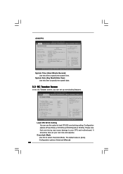
... [Auto] [Auto] Overclocking may cause damage to your CPU and motherboard. It should be done at your own risk and expense. Please note that overclocing may cause damage to your CPU and motherboard. AD425PV3 BIOS SETUP UTILITY Main OC Tweaker Advanced H/W Monitor Boot Security Exit ...System Overview System Time System Date [14:00:09] [Fri 11/19/2010] BIOS Version : AD425PV3 P1.00 Processor Type : Intel (R) Atom ...
... [Auto] [Auto] Overclocking may cause damage to your CPU and motherboard. It should be done at your own risk and expense. Please note that overclocing may cause damage to your CPU and motherboard. AD425PV3 BIOS SETUP UTILITY Main OC Tweaker Advanced H/W Monitor Boot Security Exit ...System Overview System Time System Date [14:00:09] [Fri 11/19/2010] BIOS Version : AD425PV3 P1.00 Processor Type : Intel (R) Atom ...

User Manual
Page 27
... DDR3_800]. Min: 5. Min: 3. CPU Frequency (MHz) Use this option to adjust CPU frequency. Max: 10. Max: 10. Max: 10. The default value is selected, the motherboard will detect the memory module(s) inserted and assigns appropriate frequency automatically. Min = 3 Max = 7 +F1 F9 F10 ESC Select Screen Select Item Change Option General Help...
... DDR3_800]. Min: 5. Min: 3. CPU Frequency (MHz) Use this option to adjust CPU frequency. Max: 10. Max: 10. Max: 10. The default value is selected, the motherboard will detect the memory module(s) inserted and assigns appropriate frequency automatically. Min = 3 Max = 7 +F1 F9 F10 ESC Select Screen Select Item Change Option General Help...
User Manual
Page 31
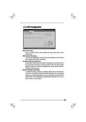
... of this feature, it requires a computer system with "No Execute (NX) Memory Protection" can prevent data pages from overheated. Hyper Threading Technology To enable this motherboard. 3.4.1 CPU Configuration BIOS SETUP UTILITY Advanced CPU Configuration Ratio Actual Value CPU Thermal Throttling No-Execute Memory Protection Hyper Threading Technology 9 [Enabled] [Disabled] [Enabled] Enter...
... of this feature, it requires a computer system with "No Execute (NX) Memory Protection" can prevent data pages from overheated. Hyper Threading Technology To enable this motherboard. 3.4.1 CPU Configuration BIOS SETUP UTILITY Advanced CPU Configuration Ratio Actual Value CPU Thermal Throttling No-Execute Memory Protection Hyper Threading Technology 9 [Enabled] [Disabled] [Enabled] Enter...

User Manual
Page 32
... Mode] [Maximum DVMT] [Auto] [Auto] [Enabled] Select the type of primary VGA in this item if you set DVMT Mode Select as needed for the motherboard through efficient memory utilization. The default value is [DVMT Mode]. If you select [Enabled, 8MB], the onboard VGA will be enabled. In Fixed mode, a fixed...
... Mode] [Maximum DVMT] [Auto] [Auto] [Enabled] Select the type of primary VGA in this item if you set DVMT Mode Select as needed for the motherboard through efficient memory utilization. The default value is [DVMT Mode]. If you select [Enabled, 8MB], the onboard VGA will be enabled. In Fixed mode, a fixed...

