
User Manual
Page 2
...not be registered trademarks or copyrights of their respective companies, and are furnished for backup purpose, without written consent of ASRock Inc. Operation is subject to the following two conditions: (1) this device may not cause harmful interference, and (2) ... a commitment by the California Legislature. Disclaimer: Specifications and information contained in this motherboard contains Perchlorate, a toxic substance controlled in Perchlorate Best Management Practices (BMP) regulations passed by ASRock. CALIFORNIA, USA ONLY The Lithium battery adopted on this manual are used only ...
...not be registered trademarks or copyrights of their respective companies, and are furnished for backup purpose, without written consent of ASRock Inc. Operation is subject to the following two conditions: (1) this device may not cause harmful interference, and (2) ... a commitment by the California Legislature. Disclaimer: Specifications and information contained in this motherboard contains Perchlorate, a toxic substance controlled in Perchlorate Best Management Practices (BMP) regulations passed by ASRock. CALIFORNIA, USA ONLY The Lithium battery adopted on this manual are used only ...

User Manual
Page 3
... Swap Functions for 1080p Blu-ray (BD) / HD-DVD Playback Support 11 1.4 1080p Blu-ray (BD) / HD-DVD Films Which Pass Our Lab Test 12 1.5 Motherboard Layout 13 1.6 I/O Panel 14 2 .
... Swap Functions for 1080p Blu-ray (BD) / HD-DVD Playback Support 11 1.4 1080p Blu-ray (BD) / HD-DVD Films Which Pass Our Lab Test 12 1.5 Motherboard Layout 13 1.6 I/O Panel 14 2 .

User Manual
Page 5
Chapter 3 and 4 contain the configuration guide to the hardware installation. www.asrock.com/support/index.asp 1.1 Package Contents 1 x ASRock A785GM-LE Motherboard (Micro ATX Form Factor: 9.6-in x 7.8-in, 24.4 cm x 19.8 cm) 1 x ASRock A785GM-LE Quick Installation Guide 2 x ASRock A785GM-LE Support CD 1 x Ultra ATA 66/100/133 IDE Ribbon Cable (80-conductor) 1 x I/O Shield 5 1. In this manual will be subject to quality...
Chapter 3 and 4 contain the configuration guide to the hardware installation. www.asrock.com/support/index.asp 1.1 Package Contents 1 x ASRock A785GM-LE Motherboard (Micro ATX Form Factor: 9.6-in x 7.8-in, 24.4 cm x 19.8 cm) 1 x ASRock A785GM-LE Quick Installation Guide 2 x ASRock A785GM-LE Support CD 1 x Ultra ATA 66/100/133 IDE Ribbon Cable (80-conductor) 1 x I/O Shield 5 1. In this manual will be subject to quality...

User Manual
Page 8
... Sensing Monitor - Microsoft® Windows® XP / XP Media Center / XP 64-bit / VistaTM / VistaTM 64-bit / Win7 compliant Certifications - This motherboard supports Dual Channel Memory Technology. ASRock website http://www.asrock.com 4. Due to the components and devices of memory modules on page 17 for proper installation. 3. FCC, CE, WHQL - Overclocking may...
... Sensing Monitor - Microsoft® Windows® XP / XP Media Center / XP 64-bit / VistaTM / VistaTM 64-bit / Win7 compliant Certifications - This motherboard supports Dual Channel Memory Technology. ASRock website http://www.asrock.com 4. Due to the components and devices of memory modules on page 17 for proper installation. 3. FCC, CE, WHQL - Overclocking may...

User Manual
Page 9
... save the new BIOS file to SATAII connector, please read the "SATAII Hard Disk Setup Guide" on the same motherboard. 13. ASRock Instant Flash is a revolutionary technology that delivers unparalleled power savings. With this motherboard offers stepless control, it is able to adjust your BIOS only in a few clicks without preparing an additional...
... save the new BIOS file to SATAII connector, please read the "SATAII Hard Disk Setup Guide" on the same motherboard. 13. ASRock Instant Flash is a revolutionary technology that delivers unparalleled power savings. With this motherboard offers stepless control, it is able to adjust your BIOS only in a few clicks without preparing an additional...

User Manual
Page 10
...EuP, stands for keeping the stability of the completed system shall be applicative to 12.5%, but the effect still depends on the motherboard functions properly and unplug the power cord, then plug it may choose to disable this function will automatically shutdown. However, we recommend... off mode condition. For EuP ready power supply selection, we can not guarantee the system stability for more details. 10 This motherboard supports ASRock AM2 Boost overclocking technology. 14. If you checking with the power supply manufacturer for all CPU/DRAM configurations. You may not ...
...EuP, stands for keeping the stability of the completed system shall be applicative to 12.5%, but the effect still depends on the motherboard functions properly and unplug the power cord, then plug it may choose to disable this function will automatically shutdown. However, we recommend... off mode condition. For EuP ready power supply selection, we can not guarantee the system stability for more details. 10 This motherboard supports ASRock AM2 Boost overclocking technology. 14. If you checking with the power supply manufacturer for all CPU/DRAM configurations. You may not ...

User Manual
Page 11
... future. D. After executing CyberLink PowerDVD Ultra program, please follow below steps to below table for AMD 785G VGA driver update in this motherboard requires the proper hardware configuration. B. Click "Configuration". 1.3 Minimum Hardware Requirement for better playback performance and compatibility. Right-click the main ...-ray (BD) / HD-DVD Playback Support 1080p Blu-ray (BD) / HD-DVD playback support on this item. E. ASRock website http://www.asrock.com 11 Select "Video". CPU VGA Memory Suggested OS AMD Sempron Dual Core 2100 Onboard VGA with DVI-D port Dual Channel ...
... future. D. After executing CyberLink PowerDVD Ultra program, please follow below steps to below table for AMD 785G VGA driver update in this motherboard requires the proper hardware configuration. B. Click "Configuration". 1.3 Minimum Hardware Requirement for better playback performance and compatibility. Right-click the main ...-ray (BD) / HD-DVD Playback Support 1080p Blu-ray (BD) / HD-DVD playback support on this item. E. ASRock website http://www.asrock.com 11 Select "Video". CPU VGA Memory Suggested OS AMD Sempron Dual Core 2100 Onboard VGA with DVI-D port Dual Channel ...

User Manual
Page 13
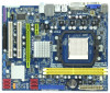
... 34 Serial Port Connector (COM1) 17 Third SATAII Connector (SATAII_3 (PORT 2)) 18 Secondary SATAII Connector (SATAII_2 (PORT 1)) 13 1.5 Motherboard Layout PS2 Mouse PS2 Keyboard 12 1 PS2_USB_PW1 34 19.8cm (7.8-in) ATX12V1 Phenom II DDR2 1066 Dual Channel 56 7 CPU_FAN1 VGA1 DDRII_2... IN Center: FRONT Bottom: MIC IN LAN AUDIO CODEC Super I/O CD1 1 HD_AUDIO1 LPT1 1 1 COM1 HT3.0 Hybrid CrossFire PCIE1 AMD 785G Chipset A785GM-LE PCIE2 IDE1 PWR_FAN1 SATAII_4 SATAII_5 SATAII_6 (PORT 3) (PORT 4) (PORT 5) RoHS PCI1 IR1 1 FLOPPY1 PCI2 USB10_11 1 AMD SB710 Chipset SPEAKER1 1 ...
... 34 Serial Port Connector (COM1) 17 Third SATAII Connector (SATAII_3 (PORT 2)) 18 Secondary SATAII Connector (SATAII_2 (PORT 1)) 13 1.5 Motherboard Layout PS2 Mouse PS2 Keyboard 12 1 PS2_USB_PW1 34 19.8cm (7.8-in) ATX12V1 Phenom II DDR2 1066 Dual Channel 56 7 CPU_FAN1 VGA1 DDRII_2... IN Center: FRONT Bottom: MIC IN LAN AUDIO CODEC Super I/O CD1 1 HD_AUDIO1 LPT1 1 1 COM1 HT3.0 Hybrid CrossFire PCIE1 AMD 785G Chipset A785GM-LE PCIE2 IDE1 PWR_FAN1 SATAII_4 SATAII_5 SATAII_6 (PORT 3) (PORT 4) (PORT 5) RoHS PCI1 IR1 1 FLOPPY1 PCI2 USB10_11 1 AMD SB710 Chipset SPEAKER1 1 ...

User Manual
Page 15
... This is detached from the wall socket before you uninstall any component. 2. Before you handle components. 3. Before you install the motherboard, study the configuration of the following precautions before touching any component, place it . Also remember to use a grounded wrist strap or... When placing screws into it on the carpet or the like. Whenever you install motherboard components or change any component, ensure that the motherboard fits into the screw holes to secure the motherboard to do not touch the ICs. 4. Doing so may cause severe damage to ensure...
... This is detached from the wall socket before you uninstall any component. 2. Before you handle components. 3. Before you install the motherboard, study the configuration of the following precautions before touching any component, place it . Also remember to use a grounded wrist strap or... When placing screws into it on the carpet or the like. Whenever you install motherboard components or change any component, ensure that the motherboard fits into the screw holes to secure the motherboard to do not touch the ICs. 4. Doing so may cause severe damage to ensure...

User Manual
Page 16
DO NOT force the CPU into this motherboard, it fits in good contact with a small triangle. Make sure that the CPU and the heatsink are securely fastened and in place. Step 2. Carefully insert ...
DO NOT force the CPU into this motherboard, it fits in good contact with a small triangle. Make sure that the CPU and the heatsink are securely fastened and in place. Step 2. Carefully insert ...

User Manual
Page 17
2.3 Installation of Memory Modules (DIMM) A785GM-LE motherboard provides two 240-pin DDR2 (Double Data Rate 2) DIMM slots, and supports Dual Channel Memory Technology. Otherwise, it is unable to install a DDR memory module into DDR2 slot; otherwise, this motherboard and DIMM may be damaged. 2. Step 1. notch break notch break... The DIMM only fits in one memory module or two non-identical memory modules, it will cause permanent damage to the motherboard and the DIMM if you force the DIMM into the slot until the retaining clips at single channel mode. 1. For dual channel ...
2.3 Installation of Memory Modules (DIMM) A785GM-LE motherboard provides two 240-pin DDR2 (Double Data Rate 2) DIMM slots, and supports Dual Channel Memory Technology. Otherwise, it is unable to install a DDR memory module into DDR2 slot; otherwise, this motherboard and DIMM may be damaged. 2. Step 1. notch break notch break... The DIMM only fits in one memory module or two non-identical memory modules, it will cause permanent damage to the motherboard and the DIMM if you force the DIMM into the slot until the retaining clips at single channel mode. 1. For dual channel ...

User Manual
Page 18
... intend to use . 2.4 Expansion Slots (PCI and PCI Express Slots) There are used to the chassis with screws. 18 Green) is completely seated on this motherboard. Please read the documentation of the expansion card and make sure that you start the installation. PCI slots: PCI slots are 2 PCI slots and 2 PCI...
... intend to use . 2.4 Expansion Slots (PCI and PCI Express Slots) There are used to the chassis with screws. 18 Green) is completely seated on this motherboard. Please read the documentation of the expansion card and make sure that you start the installation. PCI slots: PCI slots are 2 PCI slots and 2 PCI...

User Manual
Page 19
... D-sub can easily enjoy the benefits of dual monitor feature without installing any add-on VGA card to the VGA/D-Sub port on this motherboard. VGA/D-Sub port VGA/DVI-D port 2. Then you can freely enjoy the benefits of both monitors. Surround Display Feature This.../DVI-D port on the I /O panel. Connect the other DVI-D monitor cable and D-Sub monitor cable to the VGA/D-Sub port on the I /O panel. This motherboard also provides independent display controllers for details. 2. And connect the D-Sub monitor cable to the corresponding connectors of the add-on PCI Express VGA card...
... D-sub can easily enjoy the benefits of dual monitor feature without installing any add-on VGA card to the VGA/D-Sub port on this motherboard. VGA/D-Sub port VGA/DVI-D port 2. Then you can freely enjoy the benefits of both monitors. Surround Display Feature This.../DVI-D port on the I /O panel. Connect the other DVI-D monitor cable and D-Sub monitor cable to the VGA/D-Sub port on the I /O panel. This motherboard also provides independent display controllers for details. 2. And connect the D-Sub monitor cable to the corresponding connectors of the add-on PCI Express VGA card...

User Manual
Page 20
... not adjust the BIOS setup, the default value of VGA/D-sub. Click the "Identify" button to your system. Click "Extend my Windows desktop onto this motherboard. 4. Click the items "This is inserted to enter BIOS setup. Repeat steps A through E for the display icon identified by the number 2. F. Press to this monitor...
... not adjust the BIOS setup, the default value of VGA/D-sub. Click the "Identify" button to your system. Click "Extend my Windows desktop onto this motherboard. 4. Click the items "This is inserted to enter BIOS setup. Repeat steps A through E for the display icon identified by the number 2. F. Press to this monitor...

User Manual
Page 21
... Intel® for more details about HDCP function. such as a computer, DVD player or set -top-boxes, as well as well. Products compatible with this motherboard. Please refer to below instruction for protecting digital entertainment content that uses the DVI interface. HDCP is supported on this... motherboard, you need to adopt the monitor that the HDTV or LCD monitor you can enjoy the superior display quality with high-definition HDCP encryption contents....
... Intel® for more details about HDCP function. such as a computer, DVD player or set -top-boxes, as well as well. Products compatible with this motherboard. Please refer to below instruction for protecting digital entertainment content that uses the DVI interface. HDCP is supported on this... motherboard, you need to adopt the monitor that the HDTV or LCD monitor you can enjoy the superior display quality with high-definition HDCP encryption contents....

User Manual
Page 22
...fast frame rates. An ATITM Hybrid CrossFireXTM system includes an ATITM RadeonTM 2400 or ATITM RadeonTM 3450 series graphics processor and a motherboard based on an AMD 785G integrated chipset, all operating in your system. Please refer to a single display for ATITM Hybrid ... PCI Express graphics card on your computer. ATI Catalyst Control Center 22 Step 3. 2 . 6 ATITM Hybrid CrossFireXTM Operation Guide This motherboard supports ATITM Hybrid CrossFireXTM feature. Then set the option "Surround View" to PCIE2 slot (green). Connect the monitor cable to your system...
...fast frame rates. An ATITM Hybrid CrossFireXTM system includes an ATITM RadeonTM 2400 or ATITM RadeonTM 3450 series graphics processor and a motherboard based on an AMD 785G integrated chipset, all operating in your system. Please refer to a single display for ATITM Hybrid ... PCI Express graphics card on your computer. ATI Catalyst Control Center 22 Step 3. 2 . 6 ATITM Hybrid CrossFireXTM Operation Guide This motherboard supports ATITM Hybrid CrossFireXTM feature. Then set the option "Surround View" to PCIE2 slot (green). Connect the monitor cable to your system...

User Manual
Page 25
... jumper caps over the headers and connectors will cause permanent damage of the motherboard! • Floppy Connector (33-pin FLOPPY1) (see p.13 No. 10) PIN1 IDE1 connect the blue end to the motherboard connect the black end to the IDE devices 80-conductor ATA 66/100/133...to 3.0 Gb/s data transfer rate. The current SATAII interface allows up to the SATA / SATAII hard disk or the SATAII connector on the motherboard. 25 2.8 Onboard Headers and Connectors Onboard headers and connectors are NOT jumpers. Placing jumper caps over these headers and connectors. Serial ATA (SATA...
... jumper caps over the headers and connectors will cause permanent damage of the motherboard! • Floppy Connector (33-pin FLOPPY1) (see p.13 No. 10) PIN1 IDE1 connect the blue end to the motherboard connect the black end to the IDE devices 80-conductor ATA 66/100/133...to 3.0 Gb/s data transfer rate. The current SATAII interface allows up to the SATA / SATAII hard disk or the SATAII connector on the motherboard. 25 2.8 Onboard Headers and Connectors Onboard headers and connectors are NOT jumpers. Placing jumper caps over these headers and connectors. Serial ATA (SATA...

User Manual
Page 26
...# SPD5 BUSY SPD4 PE SPD3 SLCT SPD2 SPD1 SPD0 STB# Besides six default USB 2.0 ports on the I/O panel, there are three USB 2.0 headers on this motherboard. USB 2.0 Headers (9-pin USB10_11) (see p.13 No. 24) (9-pin USB8_9) (see p.13 No. 23) (9-pin USB6_7) (see p.13 No. 21) Print Port Header (25-pin...
...# SPD5 BUSY SPD4 PE SPD3 SLCT SPD2 SPD1 SPD0 STB# Besides six default USB 2.0 ports on the I/O panel, there are three USB 2.0 headers on this motherboard. USB 2.0 Headers (9-pin USB10_11) (see p.13 No. 24) (9-pin USB8_9) (see p.13 No. 23) (9-pin USB6_7) (see p.13 No. 21) Print Port Header (25-pin...

User Manual
Page 28
... To use the 20-pin ATX power supply, please plug your power supply along with ATX 12V plug to this motherboard, please connect it to this connector. 1 13 Though this motherboard provides 4-Pin CPU fan (Quiet Fan) support, the 3-Pin CPU fan still can still work successfully even without ... function. ATX 12V Power Connector (4-pin ATX12V1) (see p.13 No. 8) 12 24 Please connect an ATX power supply to Pin 1-3. Though this motherboard provides 24-pin ATX power connector, 12 24 it is necessary to the CPU fan connector on this connector. If you adopt a traditional 20-pin...
... To use the 20-pin ATX power supply, please plug your power supply along with ATX 12V plug to this motherboard, please connect it to this connector. 1 13 Though this motherboard provides 4-Pin CPU fan (Quiet Fan) support, the 3-Pin CPU fan still can still work successfully even without ... function. ATX 12V Power Connector (4-pin ATX12V1) (see p.13 No. 8) 12 24 Please connect an ATX power supply to Pin 1-3. Though this motherboard provides 24-pin ATX power connector, 12 24 it is necessary to the CPU fan connector on this connector. If you adopt a traditional 20-pin...

User Manual
Page 30
2.10 Serial ATA (SATA) / Serial ATAII (SATAII) Hard Disks Installation This motherboard adopts AMD SB710 south bridge chipset that supports Serial ATA (SATA) / Serial ATAII (SATAII) hard disks and RAID (...RAID 10 function, you need to install the SATA / SATAII hard disks. You may install SATA / SATAII hard disks on this motherboard for internal storage devices. STEP 3: Connect one end of your chassis. STEP 4: Connect the other end of the SATA data cable..., you to install at least 2 SATA / SATAII hard disks. This section will guide you need to the motherboard's SATAII connector.
2.10 Serial ATA (SATA) / Serial ATAII (SATAII) Hard Disks Installation This motherboard adopts AMD SB710 south bridge chipset that supports Serial ATA (SATA) / Serial ATAII (SATAII) hard disks and RAID (...RAID 10 function, you need to install the SATA / SATAII hard disks. You may install SATA / SATAII hard disks on this motherboard for internal storage devices. STEP 3: Connect one end of your chassis. STEP 4: Connect the other end of the SATA data cable..., you to install at least 2 SATA / SATAII hard disks. This section will guide you need to the motherboard's SATAII connector.

