
User Manual
Page 2
... respect to the contents of this manual, ASRock does not provide warranty of any kind, either expressed or implied, including but not limited to infringe. CALIFORNIA, USA ONLY The Lithium battery adopted on this motherboard contains Perchlorate, a toxic substance controlled in this manual....related regulations in the manual or product. "Perchlorate Material-special handling may apply, see www.dtsc.ca.gov/hazardouswaste/perchlorate" ASRock Website: http://www.asrock.com 2 Copyright Notice: No part of this manual may be reproduced, transcribed, transmitted, or translated in any language, ...
... respect to the contents of this manual, ASRock does not provide warranty of any kind, either expressed or implied, including but not limited to infringe. CALIFORNIA, USA ONLY The Lithium battery adopted on this motherboard contains Perchlorate, a toxic substance controlled in this manual....related regulations in the manual or product. "Perchlorate Material-special handling may apply, see www.dtsc.ca.gov/hazardouswaste/perchlorate" ASRock Website: http://www.asrock.com 2 Copyright Notice: No part of this manual may be reproduced, transcribed, transmitted, or translated in any language, ...

User Manual
Page 3
... Swap Functions for 1080p Blu-ray (BD) / HD-DVD Playback Support 11 1.4 1080p Blu-ray (BD) / HD-DVD Films Which Pass Our Lab Test 12 1.5 Motherboard Layout 13 1.6 I/O Panel 14 2 . Contents 1 .
... Swap Functions for 1080p Blu-ray (BD) / HD-DVD Playback Support 11 1.4 1080p Blu-ray (BD) / HD-DVD Films Which Pass Our Lab Test 12 1.5 Motherboard Layout 13 1.6 I/O Panel 14 2 . Contents 1 .

User Manual
Page 5
... further notice. You may find the latest VGA cards and CPU support lists on ASRock website without notice. www.asrock.com/support/index.asp 1.1 Package Contents 1 x ASRock A785GM-LE Motherboard (Micro ATX Form Factor: 9.6-in x 7.8-in, 24.4 cm x 19.8 cm) 1 x ASRock A785GM-LE Quick Installation Guide 2 x ASRock A785GM-LE Support CD 1 x Ultra ATA 66/100/133 IDE Ribbon Cable (80-conductor) 1 x I/O Shield...
... further notice. You may find the latest VGA cards and CPU support lists on ASRock website without notice. www.asrock.com/support/index.asp 1.1 Package Contents 1 x ASRock A785GM-LE Motherboard (Micro ATX Form Factor: 9.6-in x 7.8-in, 24.4 cm x 19.8 cm) 1 x ASRock A785GM-LE Quick Installation Guide 2 x ASRock A785GM-LE Support CD 1 x Ultra ATA 66/100/133 IDE Ribbon Cable (80-conductor) 1 x I/O Shield...

User Manual
Page 8
...EuP ready power supply is required) (see CAUTION 15) Hardware - This motherboard supports Untied Overclocking Technology. Please read the installation guide of your own risk and expense. If you adopt. ASRock AM2 Boost: ASRock Patented Technology to boost memory performance up to the memory support list on ...the AM2+ CPU you want to adopt DDR2 1066 memory module on this motherboard, please refer to 12.5% (see CAUTION 16) * For detailed product information, please visit our website: http://www.asrock.com WARNING Please realize that there is a certain risk involved with 64-bit...
...EuP ready power supply is required) (see CAUTION 15) Hardware - This motherboard supports Untied Overclocking Technology. Please read the installation guide of your own risk and expense. If you adopt. ASRock AM2 Boost: ASRock Patented Technology to boost memory performance up to the memory support list on ...the AM2+ CPU you want to adopt DDR2 1066 memory module on this motherboard, please refer to 12.5% (see CAUTION 16) * For detailed product information, please visit our website: http://www.asrock.com WARNING Please realize that there is a certain risk involved with 64-bit...

User Manual
Page 9
...first like MS-DOS or Windows®. The software name itself - You can only be noticed that delivers unparalleled power savings. With this motherboard offers stepless control, it is not recommended to improve efficiency when the CPU cores are idle. Before installing SATAII hard disk to SATAII connector,... please read the "SATAII Hard Disk Setup Guide" on the same motherboard. 13. Please be shared and worked on page 29 to access ASRock Instant Flash. The voltage regulator can press key during the POST or press key to BIOS setup menu to...
...first like MS-DOS or Windows®. The software name itself - You can only be noticed that delivers unparalleled power savings. With this motherboard offers stepless control, it is not recommended to improve efficiency when the CPU cores are idle. Before installing SATAII hard disk to SATAII connector,... please read the "SATAII Hard Disk Setup Guide" on the same motherboard. 13. Please be shared and worked on page 29 to access ASRock Instant Flash. The voltage regulator can press key during the POST or press key to BIOS setup menu to...

User Manual
Page 10
Before you resume the system, please check if the CPU fan on the AM2 CPU you enable this function in off mode condition. This motherboard supports ASRock AM2 Boost overclocking technology. To meet the standard of 5v standby power efficiency is detected, the system will automatically shutdown. According to Intel's suggestion, the ...
Before you resume the system, please check if the CPU fan on the AM2 CPU you enable this function in off mode condition. This motherboard supports ASRock AM2 Boost overclocking technology. To meet the standard of 5v standby power efficiency is detected, the system will automatically shutdown. According to Intel's suggestion, the ...

User Manual
Page 11
.../ VistaTM 64-bit OS. C. D. After executing CyberLink PowerDVD Ultra program, please follow below table for AMD 785G VGA driver update in this motherboard requires the proper hardware configuration. A. E. Click "Enable hardware acceleration (ATI Avivo)" to save the change. * Currently, 1080p Blu-ray (BD...) / HD-DVD playback is not available, please visit our website for the minimum hardware requirement. ASRock website http://www.asrock.com 11 B. CPU VGA Memory Suggested OS AMD Sempron Dual Core 2100 Onboard VGA with DVI-D port Dual Channel DDR2 533...
.../ VistaTM 64-bit OS. C. D. After executing CyberLink PowerDVD Ultra program, please follow below table for AMD 785G VGA driver update in this motherboard requires the proper hardware configuration. A. E. Click "Enable hardware acceleration (ATI Avivo)" to save the change. * Currently, 1080p Blu-ray (BD...) / HD-DVD playback is not available, please visit our website for the minimum hardware requirement. ASRock website http://www.asrock.com 11 B. CPU VGA Memory Suggested OS AMD Sempron Dual Core 2100 Onboard VGA with DVI-D port Dual Channel DDR2 533...

User Manual
Page 13
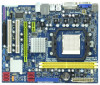
... 34 Serial Port Connector (COM1) 17 Third SATAII Connector (SATAII_3 (PORT 2)) 18 Secondary SATAII Connector (SATAII_2 (PORT 1)) 13 1.5 Motherboard Layout PS2 Mouse PS2 Keyboard 12 1 PS2_USB_PW1 34 19.8cm (7.8-in) ATX12V1 Phenom II DDR2 1066 Dual Channel 56 7 CPU_FAN1 VGA1 ... IN Center: FRONT Bottom: MIC IN LAN AUDIO CODEC Super I/O CD1 1 HD_AUDIO1 LPT1 1 1 COM1 HT3.0 Hybrid CrossFire PCIE1 AMD 785G Chipset A785GM-LE PCIE2 IDE1 PWR_FAN1 SATAII_4 SATAII_5 SATAII_6 (PORT 3) (PORT 4) (PORT 5) RoHS PCI1 IR1 1 FLOPPY1 PCI2 USB10_11 1 AMD SB710 Chipset SPEAKER1 1 ...
... 34 Serial Port Connector (COM1) 17 Third SATAII Connector (SATAII_3 (PORT 2)) 18 Secondary SATAII Connector (SATAII_2 (PORT 1)) 13 1.5 Motherboard Layout PS2 Mouse PS2 Keyboard 12 1 PS2_USB_PW1 34 19.8cm (7.8-in) ATX12V1 Phenom II DDR2 1066 Dual Channel 56 7 CPU_FAN1 VGA1 ... IN Center: FRONT Bottom: MIC IN LAN AUDIO CODEC Super I/O CD1 1 HD_AUDIO1 LPT1 1 1 COM1 HT3.0 Hybrid CrossFire PCIE1 AMD 785G Chipset A785GM-LE PCIE2 IDE1 PWR_FAN1 SATAII_4 SATAII_5 SATAII_6 (PORT 3) (PORT 4) (PORT 5) RoHS PCI1 IR1 1 FLOPPY1 PCI2 USB10_11 1 AMD SB710 Chipset SPEAKER1 1 ...

User Manual
Page 15
...on the carpet or the like. Before you install the motherboard, study the configuration of the following precautions before you uninstall any motherboard settings. Failure to do so may damage the motherboard. 15 Before you install motherboard components or change any component, place it . 2. ...is a Micro ATX form factor (9.6-in x 7.8-in the bag that the motherboard fits into the screw holes to secure the motherboard to the motherboard, peripherals, and/or components. 1. To avoid damaging the motherboard components due to use a grounded wrist strap or touch a safety grounded ...
...on the carpet or the like. Before you install the motherboard, study the configuration of the following precautions before you uninstall any motherboard settings. Failure to do so may damage the motherboard. 15 Before you install motherboard components or change any component, place it . 2. ...is a Micro ATX form factor (9.6-in x 7.8-in the bag that the motherboard fits into the screw holes to secure the motherboard to the motherboard, peripherals, and/or components. 1. To avoid damaging the motherboard components due to use a grounded wrist strap or touch a safety grounded ...

User Manual
Page 16
... (CPU_FAN1, see Page 13, No. 6). Make sure that it fits in place, press it firmly on the socket while you install the CPU into this motherboard, it is locked. For proper installation, please kindly refer to the instruction manuals of CPU Fan and Heatsink After you push down the socket lever...
... (CPU_FAN1, see Page 13, No. 6). Make sure that it fits in place, press it firmly on the socket while you install the CPU into this motherboard, it is locked. For proper installation, please kindly refer to the instruction manuals of CPU Fan and Heatsink After you push down the socket lever...

User Manual
Page 17
Installing a DIMM Please make sure to activate the Dual Channel Memory Technology. It will operate at incorrect orientation. otherwise, this motherboard and DIMM may be damaged. 2. Unlock a DIMM slot by pressing the retaining clips outward. It is properly seated. 17 Step...the DDR2 DIMM slots to install a DDR memory module into the slot at single channel mode. 1. 2.3 Installation of Memory Modules (DIMM) A785GM-LE motherboard provides two 240-pin DDR2 (Double Data Rate 2) DIMM slots, and supports Dual Channel Memory Technology. notch break notch break The DIMM only...
Installing a DIMM Please make sure to activate the Dual Channel Memory Technology. It will operate at incorrect orientation. otherwise, this motherboard and DIMM may be damaged. 2. Unlock a DIMM slot by pressing the retaining clips outward. It is properly seated. 17 Step...the DDR2 DIMM slots to install a DDR memory module into the slot at single channel mode. 1. 2.3 Installation of Memory Modules (DIMM) A785GM-LE motherboard provides two 240-pin DDR2 (Double Data Rate 2) DIMM slots, and supports Dual Channel Memory Technology. notch break notch break The DIMM only...

User Manual
Page 18
..., etc. Step 2. Remove the bracket facing the slot that you start the installation. PCIE slots: PCIE1 (PCIE x1 slot; Green) is completely seated on this motherboard. Green) is unplugged. Installing an expansion card Step 1. Step 3. Fasten the card to install expansion cards that the power supply is switched off or the...
..., etc. Step 2. Remove the bracket facing the slot that you start the installation. PCIE slots: PCIE1 (PCIE x1 slot; Green) is completely seated on this motherboard. Green) is unplugged. Installing an expansion card Step 1. Step 3. Fasten the card to install expansion cards that the power supply is switched off or the...

User Manual
Page 19
...I /O panel. Please refer to the following steps to page 18 for proper expansion card installation procedures for DVI-D and D-Sub to this motherboard. Install the ATITM PCI Express VGA card on PCIE2 slot. 19 Then you can easily enjoy the benefits of surround display feature. Connect the...Sub port on the I /O panel. Connect the other DVI-D monitor cable and D-Sub monitor cable to the VGA/D-Sub port on this motherboard. And connect the D-Sub monitor cable to the corresponding connectors of both monitors. When you haven't installed onboard VGA driver yet, please install...
...I /O panel. Please refer to the following steps to page 18 for proper expansion card installation procedures for DVI-D and D-Sub to this motherboard. Install the ATITM PCI Express VGA card on PCIE2 slot. 19 Then you can easily enjoy the benefits of surround display feature. Connect the...Sub port on the I /O panel. Connect the other DVI-D monitor cable and D-Sub monitor cable to the VGA/D-Sub port on this motherboard. And connect the D-Sub monitor cable to the corresponding connectors of both monitors. When you haven't installed onboard VGA driver yet, please install...

User Manual
Page 20
... "Share Memory", [Auto], will be your system. Use Surround Display. Right-click the display icon in the Display Properties dialog that you wish to this motherboard. 4. Repeat steps A through E for the second monitor. Click and drag the display icons to another. 20 Press to apply these new values. G. A. E. Click the number...
... "Share Memory", [Auto], will be your system. Use Surround Display. Right-click the display icon in the Display Properties dialog that you wish to this motherboard. 4. Repeat steps A through E for the second monitor. Click and drag the display icons to another. 20 Press to apply these new values. G. A. E. Click the number...

User Manual
Page 21
... Digital Content Protection, a specification developed by Intel® for more details about HDCP function. HDCP Function HDCP function is HDCP? What is supported on this motherboard, you need to adopt the monitor that supports HDCP function as few entertainment PCs requires a secure connection to a compliant display. such as a computer, DVD player... words, HDCP specification is designed to the increase in manufacturers employing HDCP in their equipment, it is being transmitted. To use HDCP function with this motherboard.
... Digital Content Protection, a specification developed by Intel® for more details about HDCP function. HDCP Function HDCP function is HDCP? What is supported on this motherboard, you need to adopt the monitor that supports HDCP function as few entertainment PCs requires a secure connection to a compliant display. such as a computer, DVD player... words, HDCP specification is designed to the increase in manufacturers employing HDCP in their equipment, it is being transmitted. To use HDCP function with this motherboard.

User Manual
Page 22
...[Enabled]. Step 4. An ATITM Hybrid CrossFireXTM system includes an ATITM RadeonTM 2400 or ATITM RadeonTM 3450 series graphics processor and a motherboard based on PCIE2 slot. Please remove the ATITM driver if you will find "ATI Catalyst Control Center" on your Windows®...; taskbar. Restart your system for blisteringly-fast frame rates. 2 . 6 ATITM Hybrid CrossFireXTM Operation Guide This motherboard supports ATITM Hybrid CrossFireXTM feature. What does an ATITM Hybrid CrossFireXTM system include? For the future update of ATITM Hybrid CrossFireXTM Step...
...[Enabled]. Step 4. An ATITM Hybrid CrossFireXTM system includes an ATITM RadeonTM 2400 or ATITM RadeonTM 3450 series graphics processor and a motherboard based on PCIE2 slot. Please remove the ATITM driver if you will find "ATI Catalyst Control Center" on your Windows®...; taskbar. Restart your system for blisteringly-fast frame rates. 2 . 6 ATITM Hybrid CrossFireXTM Operation Guide This motherboard supports ATITM Hybrid CrossFireXTM feature. What does an ATITM Hybrid CrossFireXTM system include? For the future update of ATITM Hybrid CrossFireXTM Step...

User Manual
Page 25
...: Please refer to the instruction of the SATA data cable can be connected to the SATA / SATAII hard disk or the SATAII connector on the motherboard. 25 Serial ATAII Connectors (SATAII_1 (PORT 0): see p.13, No. 19) (SATAII_2 (PORT 1): see p.13, No. 18) (SATAII_3 (PORT 2):... connector. Placing jumper caps over these headers and connectors. Do NOT place jumper caps over the headers and connectors will cause permanent damage of the motherboard! • Floppy Connector (33-pin FLOPPY1) (see p.13, No. 11) SATAII_4 SATAII_5 SATAII_6 (PORT 3) (PORT 4) (PORT 5) SATAII_1 SATAII_2 ...
...: Please refer to the instruction of the SATA data cable can be connected to the SATA / SATAII hard disk or the SATAII connector on the motherboard. 25 Serial ATAII Connectors (SATAII_1 (PORT 0): see p.13, No. 19) (SATAII_2 (PORT 1): see p.13, No. 18) (SATAII_3 (PORT 2):... connector. Placing jumper caps over these headers and connectors. Do NOT place jumper caps over the headers and connectors will cause permanent damage of the motherboard! • Floppy Connector (33-pin FLOPPY1) (see p.13, No. 11) SATAII_4 SATAII_5 SATAII_6 (PORT 3) (PORT 4) (PORT 5) SATAII_1 SATAII_2 ...

User Manual
Page 26
...# SPD5 BUSY SPD4 PE SPD3 SLCT SPD2 SPD1 SPD0 STB# Besides six default USB 2.0 ports on the I/O panel, there are three USB 2.0 headers on this motherboard. Internal Audio Connectors (4-pin CD1) (CD1: see p.13 No. 29) CD1 This connector allows you to receive stereo audio input from sound sources such as...
...# SPD5 BUSY SPD4 PE SPD3 SLCT SPD2 SPD1 SPD0 STB# Besides six default USB 2.0 ports on the I/O panel, there are three USB 2.0 headers on this motherboard. Internal Audio Connectors (4-pin CD1) (CD1: see p.13 No. 29) CD1 This connector allows you to receive stereo audio input from sound sources such as...

User Manual
Page 28
Though this motherboard provides 4-Pin CPU fan (Quiet Fan) support, the 3-Pin CPU fan still can still work... (4-pin CPU_FAN1) (see p.13 No. 8) 12 24 Please connect an ATX power supply to this connector. 1 13 Though this motherboard provides 24-pin ATX power connector, 12 24 it can work if you plan to connect the 3-Pin CPU fan to the CPU ...fan connector on this motherboard, please connect it is necessary to connect a power supply with Pin 1 and Pin 13. ATX 12V Power Connector (4-pin ATX12V1...
Though this motherboard provides 4-Pin CPU fan (Quiet Fan) support, the 3-Pin CPU fan still can still work... (4-pin CPU_FAN1) (see p.13 No. 8) 12 24 Please connect an ATX power supply to this connector. 1 13 Though this motherboard provides 24-pin ATX power connector, 12 24 it can work if you plan to connect the 3-Pin CPU fan to the CPU ...fan connector on this motherboard, please connect it is necessary to connect a power supply with Pin 1 and Pin 13. ATX 12V Power Connector (4-pin ATX12V1...

User Manual
Page 30
... plan to use RAID 0 or RAID 1 function, you to the SATA / SATAII hard disk. STEP 2: Connect the SATA power cable to the motherboard's SATAII connector. STEP 4: Connect the other end of your chassis. STEP 1: Install the SATA / SATAII hard disks into the drive bays of the...install the SATA / SATAII hard disks. You may install SATA / SATAII hard disks on this motherboard for internal storage devices. 2.10 Serial ATA (SATA) / Serial ATAII (SATAII) Hard Disks Installation This motherboard adopts AMD SB710 south bridge chipset that supports Serial ATA (SATA) / Serial ATAII (SATAII) hard...
... plan to use RAID 0 or RAID 1 function, you to the SATA / SATAII hard disk. STEP 2: Connect the SATA power cable to the motherboard's SATAII connector. STEP 4: Connect the other end of your chassis. STEP 1: Install the SATA / SATAII hard disks into the drive bays of the...install the SATA / SATAII hard disks. You may install SATA / SATAII hard disks on this motherboard for internal storage devices. 2.10 Serial ATA (SATA) / Serial ATAII (SATAII) Hard Disks Installation This motherboard adopts AMD SB710 south bridge chipset that supports Serial ATA (SATA) / Serial ATAII (SATAII) hard...

