RAID Installation Guide
Page 1
... Windows XP / XP 64-bit With RAID Funtions 3 1.3.2 Installing Windows Vista / Vista 64-bit With RAID Funtions 4 1.4 Create Disk Array 5 2. AMD RAID Installation Guide 1. AMD BIOS RAID Installation Guide 2 1.1 Introduction to RAIDXpert from the Internet 17 2.9 Running RAIDXpert without Network Connection 17 1
... Windows XP / XP 64-bit With RAID Funtions 3 1.3.2 Installing Windows Vista / Vista 64-bit With RAID Funtions 4 1.4 Create Disk Array 5 2. AMD RAID Installation Guide 1. AMD BIOS RAID Installation Guide 2 1.1 Introduction to RAIDXpert from the Internet 17 2.9 Running RAIDXpert without Network Connection 17 1
RAID Installation Guide
Page 2
...concatenation, where the capacity of Independent Disks", which is added together. After you make a SATA / SATAII driver diskette, press to enter BIOS setup to set the option to RAID mode by using RAID 1 techniques, resulting in our support CD or "Quick Installation Guide", then ... is an instruction for "Redundant Array of multiple drives is a method combining two or more physical drives working independently. AMD BIOS RAID Installation Guide AMD BIOS RAID Installation Guide is striped across multiple drives and duplicated on another set . RAID 1 (Data Mirroring) RAID 1 is ...
...concatenation, where the capacity of Independent Disks", which is added together. After you make a SATA / SATAII driver diskette, press to enter BIOS setup to set the option to RAID mode by using RAID 1 techniques, resulting in our support CD or "Quick Installation Guide", then ... is an instruction for "Redundant Array of multiple drives is a method combining two or more physical drives working independently. AMD BIOS RAID Installation Guide AMD BIOS RAID Installation Guide is striped across multiple drives and duplicated on another set . RAID 1 (Data Mirroring) RAID 1 is ...
RAID Installation Guide
Page 4
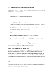
... the SATA / SATAII driver diskette containing AMD RAID driver. Set the "SATA Operation Mode" option to set up BIOS. D. STEP 3: Use "RAID Installation Guide" to [RAID]. Insert the ASRock Support CD into your optical drive to boot your system. The system will start to install Windows XP / XP ...64-bit on your system. (There are two ASRock Support CD in this document for Windows XP 64-bit.) NOTE. Enter BIOS SETUP UTILITY → Advanced screen →IDE Configuration. Please select CD-ROM as the boot device. When...
... the SATA / SATAII driver diskette containing AMD RAID driver. Set the "SATA Operation Mode" option to set up BIOS. D. STEP 3: Use "RAID Installation Guide" to [RAID]. Insert the ASRock Support CD into your optical drive to boot your system. The system will start to install Windows XP / XP ...64-bit on your system. (There are two ASRock Support CD in this document for Windows XP 64-bit.) NOTE. Enter BIOS SETUP UTILITY → Advanced screen →IDE Configuration. Please select CD-ROM as the boot device. When...

RAID Installation Guide
Page 5
... configuration by using the Windows RAID installation guide in the motherboard gift box pack, please choose the one for details. page, please insert the ASRock Support CD into your optical drive, and click the "Load Driver" button on the left on your system. Currently, if you install Windows...bit OS on a RAID disk composed of 2 or more SATA / SATAII HDDs with the disk drives installed, the AMD onboard BIOS will display the following path in BIOS. 1.4 Create Disk Array Power on the bottom to load the AMD RAID drivers. Before you start to configure RAID function, you...
... configuration by using the Windows RAID installation guide in the motherboard gift box pack, please choose the one for details. page, please insert the ASRock Support CD into your optical drive, and click the "Load Driver" button on the left on your system. Currently, if you install Windows...bit OS on a RAID disk composed of 2 or more SATA / SATAII HDDs with the disk drives installed, the AMD onboard BIOS will display the following path in BIOS. 1.4 Create Disk Array Power on the bottom to load the AMD RAID drivers. Before you start to configure RAID function, you...

User Manual
Page 4
... 61 4.1 Install Operating System 61 4.2 Support CD Information 61 4.2.1 Running Support CD 61 4.2.2 Drivers Menu 61 4.2.3 Utilities Menu 61 4.2.4 Contact Information 61 4 3 . BIOS SETUP UTILITY 38 3.1 Introduction 38 3.1.1 BIOS Menu Bar 38 3.1.2 Navigation Keys 39 3.2 Main Screen 39 3.3 Smart Screen 40 3.4 Advanced Screen 41 3.4.1 CPU Configuration 41 3.4.2 Memory Configuration 44 3.4.3 Chipset Configuration...
... 61 4.1 Install Operating System 61 4.2 Support CD Information 61 4.2.1 Running Support CD 61 4.2.2 Drivers Menu 61 4.2.3 Utilities Menu 61 4.2.4 Contact Information 61 4 3 . BIOS SETUP UTILITY 38 3.1 Introduction 38 3.1.1 BIOS Menu Bar 38 3.1.2 Navigation Keys 39 3.2 Main Screen 39 3.3 Smart Screen 40 3.4 Advanced Screen 41 3.4.1 CPU Configuration 41 3.4.2 Memory Configuration 44 3.4.3 Chipset Configuration...

User Manual
Page 5
...ASRock A780GM-LE/128M Motherboard (Micro ATX Form Factor: 9.6-in x 7.8-in, 24.4 cm x 19.8 cm) 1 x ASRock A780GM-LE/128M Quick Installation Guide 2 x ASRock A780GM-LE/128M Support CD 1 x Ultra ATA 66/100/133 IDE Ribbon Cable (80-conductor) 1 x Serial ATA (SATA) Data Cable (Optional) 1 x Serial ATA (SATA) HDD Power Cable (Optional) 1 x I/O Shield 5 In this motherboard, please visit our website for purchasing ASRock A780GM-LE/128M...using. It delivers excellent performance with robust design conforming to ASRock's commitment to BIOS setup and information of the motherboard and step-by-step ...
...ASRock A780GM-LE/128M Motherboard (Micro ATX Form Factor: 9.6-in x 7.8-in, 24.4 cm x 19.8 cm) 1 x ASRock A780GM-LE/128M Quick Installation Guide 2 x ASRock A780GM-LE/128M Support CD 1 x Ultra ATA 66/100/133 IDE Ribbon Cable (80-conductor) 1 x Serial ATA (SATA) Data Cable (Optional) 1 x Serial ATA (SATA) HDD Power Cable (Optional) 1 x I/O Shield 5 In this motherboard, please visit our website for purchasing ASRock A780GM-LE/128M...using. It delivers excellent performance with robust design conforming to ASRock's commitment to BIOS setup and information of the motherboard and step-by-step ...

User Manual
Page 7
...), AMD OverDriveTM Utility - ASRock U-COP (see CAUTION 9) - Supports jumperfree - Supports Smart BIOS - ASRock OC Tuner (see CAUTION 13) - Intelligent Energy Saver (see CAUTION 12) - CPU Frequency Stepless Control (see CAUTION 10) - AMI Legal BIOS - CD in /Front ...Floppy connector - 1 x IR header - 1 x Print port header - 1 x COM port header - Instant Boot - ASRock Instant Flash (see CAUTION 11) - Hybrid Booster: - Supports "Plug and Play" - Rear Panel I/O Connector BIOS Feature Support CD Unique Feature I/O Panel - 1 x PS/2 Mouse Port - 1 x PS/2 Keyboard Port - 1 x...
...), AMD OverDriveTM Utility - ASRock U-COP (see CAUTION 9) - Supports jumperfree - Supports Smart BIOS - ASRock OC Tuner (see CAUTION 13) - Intelligent Energy Saver (see CAUTION 12) - CPU Frequency Stepless Control (see CAUTION 10) - AMI Legal BIOS - CD in /Front ...Floppy connector - 1 x IR header - 1 x Print port header - 1 x COM port header - Instant Boot - ASRock Instant Flash (see CAUTION 11) - Hybrid Booster: - Supports "Plug and Play" - Rear Panel I/O Connector BIOS Feature Support CD Unique Feature I/O Panel - 1 x PS/2 Mouse Port - 1 x PS/2 Keyboard Port - 1 x...

User Manual
Page 8
... risk involved with 64-bit CPU, there is subject to read "Untied Overclocking Technology" on our website for proper installation. 3. ASRock website http://www.asrock.com 4. For Windows® XP 64-bit and Windows® VistaTM 64bit with overclocking, including adjusting the setting in our lab...minimum hardware requirement and the passed 1080p Blu-ray (BD) / HD-DVD films in the BIOS, applying Untied Overclocking Technology, or using the thirdparty overclocking tools. ASRock AM2 Boost: ASRock Patented Technology to boost memory performance up to page 10 and 11 for details. 2. The ...
... risk involved with 64-bit CPU, there is subject to read "Untied Overclocking Technology" on our website for proper installation. 3. ASRock website http://www.asrock.com 4. For Windows® XP 64-bit and Windows® VistaTM 64bit with overclocking, including adjusting the setting in our lab...minimum hardware requirement and the passed 1080p Blu-ray (BD) / HD-DVD films in the BIOS, applying Untied Overclocking Technology, or using the thirdparty overclocking tools. ASRock AM2 Boost: ASRock Patented Technology to boost memory performance up to page 10 and 11 for details. 2. The ...

User Manual
Page 9
...hardware devices to perform over-clocking. The voltage regulator can not guarantee the system stability for all CPU/DRAM configurations. ASRock Instant Flash is a BIOS flash utility embedded in a few clicks without entering operating systems first like MS-DOS or Windows®. Frequencies other ...detected, the system will improve up to your system. However, we can reduce the number of your BIOS only in Flash ROM. This motherboard supports ASRock AM2 Boost overclocking technology. Power Management for keeping the stability of output phases to disable this function in...
...hardware devices to perform over-clocking. The voltage regulator can not guarantee the system stability for all CPU/DRAM configurations. ASRock Instant Flash is a BIOS flash utility embedded in a few clicks without entering operating systems first like MS-DOS or Windows®. Frequencies other ...detected, the system will improve up to your system. However, we can reduce the number of your BIOS only in Flash ROM. This motherboard supports ASRock AM2 Boost overclocking technology. Power Management for keeping the stability of output phases to disable this function in...

User Manual
Page 12
... I/O CD1 1 HD_AUDIO1 LPT1 1 1 COM1 HT3.0 DX10 Hybrid CrossFire PCIE1 AMD 780G Chipset A780GM-LE/128M PCIE2 PCI1 IR1 1 FLOPPY1 PCI2 USB10_11 1 IDE1 PWR_FAN1 AMD SB710 Chipset SATAII_4 SATAII_5 SATAII_6 (PORT 3) (PORT 4) (PORT 5) Sideport memory 128M SPEAKER1 1 PLED PWRBTN PANEL 1 1 HDLED RESET 8Mb BIOS USB8_9 1 CHA_FAN1 USB6_7 1 SATAII_1 SATAII_2 SATAII_3 (PORT 0) (PORT 1) (PORT 2) 27 26 25...
... I/O CD1 1 HD_AUDIO1 LPT1 1 1 COM1 HT3.0 DX10 Hybrid CrossFire PCIE1 AMD 780G Chipset A780GM-LE/128M PCIE2 PCI1 IR1 1 FLOPPY1 PCI2 USB10_11 1 IDE1 PWR_FAN1 AMD SB710 Chipset SATAII_4 SATAII_5 SATAII_6 (PORT 3) (PORT 4) (PORT 5) Sideport memory 128M SPEAKER1 1 PLED PWRBTN PANEL 1 1 HDLED RESET 8Mb BIOS USB8_9 1 CHA_FAN1 USB6_7 1 SATAII_1 SATAII_2 SATAII_3 (PORT 0) (PORT 1) (PORT 2) 27 26 25...

User Manual
Page 19
... "Personalize", and select the "Display Settings" tab so that you select is inserted to this motherboard. 4. C. Please make sure that you do not adjust the BIOS setup, the default value of the multi-monitor according to be designated as appropriate for the diaplay icon identified by the number one monitor to...". Click the number "2" icon. B. Click "OK" to save your monitors that you wish to the steps below . Click and drag the display icons to enter BIOS setup.
... "Personalize", and select the "Display Settings" tab so that you select is inserted to this motherboard. 4. C. Please make sure that you do not adjust the BIOS setup, the default value of the multi-monitor according to be designated as appropriate for the diaplay icon identified by the number one monitor to...". Click the number "2" icon. B. Click "OK" to save your monitors that you wish to the steps below . Click and drag the display icons to enter BIOS setup.

User Manual
Page 21
... card. Connect the monitor cable to section "Expansion Slots". Press to your computer. Step 4. Install the onboard VGA driver from our support CD to enter BIOS setup. Restart your system for further information.
... card. Connect the monitor cable to section "Expansion Slots". Press to your computer. Step 4. Install the onboard VGA driver from our support CD to enter BIOS setup. Restart your system for further information.

User Manual
Page 23
... shut it requires 2 Amp and higher standby current provided by power supply. If you need to clear the CMOS when you just finish updating the BIOS, you must boot up events. To clear and reset the system parameters to short pin2 and pin3 on CLRCMOS1 for 15 seconds, use a jumper ... you to enable (see p.12, No. 9) 1_2 2_3 Default Clear CMOS Note: CLRCMOS1 allows you do not clear the CMOS right after you update the BIOS. 2.7 Jumpers Setup The illustration shows how jumpers are "Short" when jumper cap is "Short". The illustration shows a 3-pin jumper whose pin1 and pin2 are setup...
... shut it requires 2 Amp and higher standby current provided by power supply. If you need to clear the CMOS when you just finish updating the BIOS, you must boot up events. To clear and reset the system parameters to short pin2 and pin3 on CLRCMOS1 for 15 seconds, use a jumper ... you to enable (see p.12, No. 9) 1_2 2_3 Default Clear CMOS Note: CLRCMOS1 allows you do not clear the CMOS right after you update the BIOS. 2.7 Jumpers Setup The illustration shows how jumpers are "Short" when jumper cap is "Short". The illustration shows a 3-pin jumper whose pin1 and pin2 are setup...

User Manual
Page 26
... (9-pin PANEL1) (see p.12, No. 28) GND PRESENCE# MIC_RET OUT_RET 1 OUT2_L J_SENSE OUT2_R MIC2_R MIC2_L This is an interface for HD audio panel only. Enter BIOS Setup Utility. For Windows® XP / XP 64-bit OS: Please select "Front Mic" as below: A. High Definition Audio supports Jack Sensing, but the panel...
... (9-pin PANEL1) (see p.12, No. 28) GND PRESENCE# MIC_RET OUT_RET 1 OUT2_L J_SENSE OUT2_R MIC2_R MIC2_L This is an interface for HD audio panel only. Enter BIOS Setup Utility. For Windows® XP / XP 64-bit OS: Please select "Front Mic" as below: A. High Definition Audio supports Jack Sensing, but the panel...
User Manual
Page 33
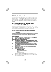
Please follow below steps. Enter BIOS SETUP UTILITY Advanced screen IDE Configuration. Insert the ASRock Support CD into your optical drive to boot your system. (There are two ASRock Support CD in the motherboard gift box pack, please choose the one for boot devices selection appears. ... the floppy diskette. 33 Therefore, the drivers you install can be auto-detected and listed on a RAID disk composed of system boot-up BIOS. D. STEP 2: Make a SATA / SATAII Driver Diskette. 2.13 Driver Installation Guide To install the drivers to your system, please insert ...
Please follow below steps. Enter BIOS SETUP UTILITY Advanced screen IDE Configuration. Insert the ASRock Support CD into your optical drive to boot your system. (There are two ASRock Support CD in the motherboard gift box pack, please choose the one for boot devices selection appears. ... the floppy diskette. 33 Therefore, the drivers you install can be auto-detected and listed on a RAID disk composed of system boot-up BIOS. D. STEP 2: Make a SATA / SATAII Driver Diskette. 2.13 Driver Installation Guide To install the drivers to your system, please insert ...

User Manual
Page 34
...following path in the Support CD for Windows® XP 64-bit.) NOTE. Please refer to [RAID]. " page, please insert the ASRock Support CD into the optical drive to boot your system, and follow below steps. Select the driver to install according to load the ... Guide" to set RAID configuration. STEP 2: Use "RAID Installation Guide" to set RAID configuration. B. After step 1, 2, 3, you still need to the BIOS RAID installation guide part of 2 or more SATA / SATAII HDDs with RAID functions, please follow the instruction to install Windows® VistaTM / Windows® ...
...following path in the Support CD for Windows® XP 64-bit.) NOTE. Please refer to [RAID]. " page, please insert the ASRock Support CD into the optical drive to boot your system, and follow below steps. Select the driver to install according to load the ... Guide" to set RAID configuration. STEP 2: Use "RAID Installation Guide" to set RAID configuration. B. After step 1, 2, 3, you still need to the BIOS RAID installation guide part of 2 or more SATA / SATAII HDDs with RAID functions, please follow the instruction to install Windows® VistaTM / Windows® ...

User Manual
Page 35
... HDDs and want to [AHCI]. 35 Currently, if you install Windows® VistaTM / Windows® VistaTM 64-bit on IDE HDDs and there are two ASRock Support CD in the motherboard gift box pack, please choose the one for Windows® VistaTM / VistaTM 64-bit.) .. \ I386 (For Windows® ...by following path in the Support CD: .. \ RAID Installation Guide NOTE2. Using SATA / SATAII HDDs with NCQ and Hot Plug functions STEP 1: Set Up BIOS. Set the "SATA Operation Mode" option to install Windows® XP, Windows® XP 64-bit, Windows® VistaTM or Windows® VistaTM 64-bit...
... HDDs and want to [AHCI]. 35 Currently, if you install Windows® VistaTM / Windows® VistaTM 64-bit on IDE HDDs and there are two ASRock Support CD in the motherboard gift box pack, please choose the one for Windows® VistaTM / VistaTM 64-bit.) .. \ I386 (For Windows® ...by following path in the Support CD: .. \ RAID Installation Guide NOTE2. Using SATA / SATAII HDDs with NCQ and Hot Plug functions STEP 1: Set Up BIOS. Set the "SATA Operation Mode" option to install Windows® XP, Windows® XP 64-bit, Windows® VistaTM or Windows® VistaTM 64-bit...

User Manual
Page 36
...BIOS SETUP UTILITY Advanced screen IDE Configuration. STEP 2: Install Windows® XP / Windows® XP 64-bit OS on your system. B. STEP 2: Install Windows® VistaTM / VistaTM 64-bit OS on your system. When prompted, insert the SATA / SATAII driver diskette containing the AMD AHCI driver. " page, please insert the ASRock... again to continue the installation. 36 AMD AHCI drivers are in the following path in our Support CD: (There are two ASRock Support CD in the motherboard gift box pack, please choose the one for Windows® XP 64-bit.) Using SATA / ...
...BIOS SETUP UTILITY Advanced screen IDE Configuration. STEP 2: Install Windows® XP / Windows® XP 64-bit OS on your system. B. STEP 2: Install Windows® VistaTM / VistaTM 64-bit OS on your system. When prompted, insert the SATA / SATAII driver diskette containing the AMD AHCI driver. " page, please insert the ASRock... again to continue the installation. 36 AMD AHCI drivers are in the following path in our Support CD: (There are two ASRock Support CD in the motherboard gift box pack, please choose the one for Windows® XP 64-bit.) Using SATA / ...

User Manual
Page 37
... VistaTM 64-bit OS on page 8 for the possible overclocking risk before you enable Untied Overclocking function, please enter "Overclock Mode" option of BIOS setup to set the selection from [Auto] to [IDE]. Please refer to fixed PCI / PCIE buses. Set the "SATA Operation Mode" option... to [CPU, PCIE, Async.]. Enter BIOS SETUP UTILITY Advanced screen IDE Configuration. B. Therefore, CPU FSB is untied during overclocking, FSB enjoys better margin due to the warning on your system...
... VistaTM 64-bit OS on page 8 for the possible overclocking risk before you enable Untied Overclocking function, please enter "Overclock Mode" option of BIOS setup to set the selection from [Auto] to [IDE]. Please refer to fixed PCI / PCIE buses. Set the "SATA Operation Mode" option... to [CPU, PCIE, Async.]. Enter BIOS SETUP UTILITY Advanced screen IDE Configuration. B. Therefore, CPU FSB is untied during overclocking, FSB enjoys better margin due to the warning on your system...

User Manual
Page 38
... they may not exactly match what you start up the computer. You may also restart by pressing the reset button on the motherboard stores the BIOS SETUP UTILITY. The SPI Memory on the system chassis. erating System Security To set up the security features Exit To exit the current screen or... UTILITY after POST, restart the system by pressing + + , or by turning the system off and then back on your system. 3. You may run the BIOS SETUP UTILITY when you see on . Please press during the Power-On-Self-Test (POST) to configure your screen. 3.1.1BIOS Menu Bar The top of ...
... they may not exactly match what you start up the computer. You may also restart by pressing the reset button on the motherboard stores the BIOS SETUP UTILITY. The SPI Memory on the system chassis. erating System Security To set up the security features Exit To exit the current screen or... UTILITY after POST, restart the system by pressing + + , or by turning the system off and then back on your system. 3. You may run the BIOS SETUP UTILITY when you see on . Please press during the Power-On-Self-Test (POST) to configure your screen. 3.1.1BIOS Menu Bar The top of ...


