
User Manual
Page 7
... RAID 1, RAID 10 and JBOD), NCQ, AHCI and "Hot Plug" functions (see CAUTION 11) - ACPI 1.1 Compliance Wake Up Events - AMI Legal BIOS - Supports jumperfree - ASRock AM2 Boost: ASRock Patented Technology to boost memory performance up to 12.5% (see CAUTION 12) - Voltage Monitoring: +12V, +5V, +3.3V, Vcore - Microsoft® Windows® XP / XP... XP 64-bit / VistaTM / VistaTM 64-bit compliant - Drivers, Utilities, AntiVirus Software (Trial Version), AMD OverDriveTM Utility - Instant Boot - CPU/Chassis/Power FAN connector - 24 pin ATX power connector - 8 pin 12V power connector -
... RAID 1, RAID 10 and JBOD), NCQ, AHCI and "Hot Plug" functions (see CAUTION 11) - ACPI 1.1 Compliance Wake Up Events - AMI Legal BIOS - Supports jumperfree - ASRock AM2 Boost: ASRock Patented Technology to boost memory performance up to 12.5% (see CAUTION 12) - Voltage Monitoring: +12V, +5V, +3.3V, Vcore - Microsoft® Windows® XP / XP... XP 64-bit / VistaTM / VistaTM 64-bit compliant - Drivers, Utilities, AntiVirus Software (Trial Version), AMD OverDriveTM Utility - Instant Boot - CPU/Chassis/Power FAN connector - 24 pin ATX power connector - 8 pin 12V power connector -
User Manual
Page 10
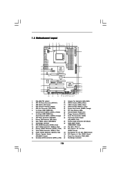
...RoHS HT3.0 PCIE1 AMD 770 Chipset PCI Express 2.0 PCIE2 CMOS BATTERY CLRCMOS1 1 Super I/O AUDIO CODEC HDMI_SPDIF1 1 CD1 HD_AUDIO1 1 1 COM1 PCIE3 A770DE+ PCI1 AMD SB710 Chipset PCI2 8Mb BIOS PCI3 FLOPPY1 IR1 1 USB10_11 1 PANEL 1 PLED PWRBTN 1 HDLED RESET USB8_9 1 USB6_7 1 SATAII_1 CHA_FAN1 ...16 1 PS2_USB_PW1 Jumper 19 Chassis Fan Connector (CHA_FAN1) 2 ATX 12V Power Connector (ATX12V1) 20 USB 2.0 Header (USB8_9, Blue) 3 AM2 940-Pin CPU Socket 21 USB 2.0 Header (USB6_7, Blue) 4 CPU Heatsink Retention Module 22 USB 2.0 Header (USB10_11, Blue) 5 CPU Fan Connector (...
...RoHS HT3.0 PCIE1 AMD 770 Chipset PCI Express 2.0 PCIE2 CMOS BATTERY CLRCMOS1 1 Super I/O AUDIO CODEC HDMI_SPDIF1 1 CD1 HD_AUDIO1 1 1 COM1 PCIE3 A770DE+ PCI1 AMD SB710 Chipset PCI2 8Mb BIOS PCI3 FLOPPY1 IR1 1 USB10_11 1 PANEL 1 PLED PWRBTN 1 HDLED RESET USB8_9 1 USB6_7 1 SATAII_1 CHA_FAN1 ...16 1 PS2_USB_PW1 Jumper 19 Chassis Fan Connector (CHA_FAN1) 2 ATX 12V Power Connector (ATX12V1) 20 USB 2.0 Header (USB8_9, Blue) 3 AM2 940-Pin CPU Socket 21 USB 2.0 Header (USB6_7, Blue) 4 CPU Heatsink Retention Module 22 USB 2.0 Header (USB10_11, Blue) 5 CPU Fan Connector (...

User Manual
Page 14
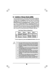
Unlock the socket by lifting the lever up to avoid bending of the pins. Position the CPU directly above the socket such that it is in good contact with a small triangle. DO NOT force the CPU into the socket ...
Unlock the socket by lifting the lever up to avoid bending of the pins. Position the CPU directly above the socket such that it is in good contact with a small triangle. DO NOT force the CPU into the socket ...
User Manual
Page 15
... installed in the same Dual Channel, for example, installing a pair of memory modules in the slots of Memory Modules (DIMM) This motherboard provides four 240-pin DDR2 (Double Data Rate 2) DIMM slots, and supports Dual Channel Memory Technology. If you always need to install a DDR memory module into DDR2 slot; 2.3 Installation...
... installed in the same Dual Channel, for example, installing a pair of memory modules in the slots of Memory Modules (DIMM) This motherboard provides four 240-pin DDR2 (Double Data Rate 2) DIMM slots, and supports Dual Channel Memory Technology. If you always need to install a DDR memory module into DDR2 slot; 2.3 Installation...
User Manual
Page 22
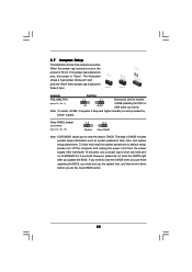
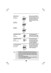
When the jumper cap is placed on pins, the jumper is "Open". The data in CMOS. Clear CMOS Jumper (CLRCMOS1) (see p.10, No. 1) +5V +5VSB +5VSB (standby) for 5 seconds...the clear-CMOS action. 22 2.7 Jumpers Setup The illustration shows how jumpers are "Short" when jumper cap is placed on these 2 pins. The illustration shows a 3-pin jumper whose pin1 and pin2 are setup. If you need to enable (see p.10, No. 10) 1_2 2_3 Default Clear CMOS ... supply. Note: To select +5VSB, it down before you update the BIOS. If no jumper cap is placed on pins, the jumper is "Short".
When the jumper cap is placed on pins, the jumper is "Open". The data in CMOS. Clear CMOS Jumper (CLRCMOS1) (see p.10, No. 1) +5V +5VSB +5VSB (standby) for 5 seconds...the clear-CMOS action. 22 2.7 Jumpers Setup The illustration shows how jumpers are "Short" when jumper cap is placed on these 2 pins. The illustration shows a 3-pin jumper whose pin1 and pin2 are setup. If you need to enable (see p.10, No. 10) 1_2 2_3 Default Clear CMOS ... supply. Note: To select +5VSB, it down before you update the BIOS. If no jumper cap is placed on pins, the jumper is "Short".
User Manual
Page 23
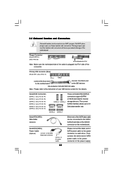
Do NOT place jumper caps over the headers and connectors will cause permanent damage of the motherboard! • Floppy Connector (33-pin FLOPPY1) (see p.10 No. 26) Pin1 FLOPPY1 the red-striped side to Pin1 Note: Make sure the red-striped side of the cable is ... headers and connectors are NOT jumpers. Please connect the black end of your IDE device vendor for internal storage devices. Primary IDE connector (Blue) (39-pin IDE1, see p.10, No. 13) SATAII_5 SATAII_6 SATAII_1 SATAII_3 These six Serial ATAII (SATAII) connectors support SATAII or SATA hard disk for the details. ...
Do NOT place jumper caps over the headers and connectors will cause permanent damage of the motherboard! • Floppy Connector (33-pin FLOPPY1) (see p.10 No. 26) Pin1 FLOPPY1 the red-striped side to Pin1 Note: Make sure the red-striped side of the cable is ... headers and connectors are NOT jumpers. Please connect the black end of your IDE device vendor for internal storage devices. Primary IDE connector (Blue) (39-pin IDE1, see p.10, No. 13) SATAII_5 SATAII_6 SATAII_1 SATAII_3 These six Serial ATAII (SATAII) connectors support SATAII or SATA hard disk for the details. ...
User Manual
Page 24
... the panel wire on this motherboard. B. Each USB 2.0 header can support two USB 2.0 ports. 1 GND P+6 P-6 USB_PWR Infrared Module Header (5-pin IR1) (see p.10, No. 28) GND PRESENCE# MIC_RET OUT_RET 1 OUT2_L J_SENSE OUT2_R MIC2_R MIC2_L This is an interface for the front panel audio... 25) IRTX +5V DUMMY 1 GND IRRX This header supports an optional wireless transmitting and receiving infrared module. USB 2.0 Headers (9-pin USB10_11) (see p.10 No. 22) (9-pin USB8_9) (see p.10 No. 20) (9-pin USB6_7) (see p.10 No. 21) USB_PWR P-11 P+11 GND DUMMY 1 GND P+10 P-10 USB_PWR USB_PWR P-9 P+9 GND...
... the panel wire on this motherboard. B. Each USB 2.0 header can support two USB 2.0 ports. 1 GND P+6 P-6 USB_PWR Infrared Module Header (5-pin IR1) (see p.10, No. 28) GND PRESENCE# MIC_RET OUT_RET 1 OUT2_L J_SENSE OUT2_R MIC2_R MIC2_L This is an interface for the front panel audio... 25) IRTX +5V DUMMY 1 GND IRRX This header supports an optional wireless transmitting and receiving infrared module. USB 2.0 Headers (9-pin USB10_11) (see p.10 No. 22) (9-pin USB8_9) (see p.10 No. 20) (9-pin USB6_7) (see p.10 No. 21) USB_PWR P-11 P+11 GND DUMMY 1 GND P+10 P-10 USB_PWR USB_PWR P-9 P+9 GND...
User Manual
Page 25
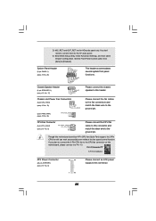
... Enter Advanced Settings, and then select Chipset Configuration. Please connect the chassis speaker to the ground pin. Enter BIOS Setup Utility. If you plan to connect the 3-Pin CPU fan to the CPU fan connector on this connector and match the black wire to this motherboard...) (see p.10 No. 8) 12 24 1 13 Please connect an ATX power supply to Pin 1-3. E. D. Set the Front Panel Control option from [Auto] to the ground pin. CPU Fan Connector (4-pin CPU_FAN1) (see p.10 No. 5) FAN_SPEED_CONTROL 4 CPU_FAN_SPEED 3 +12V 2 GND 1 Please connect the CPU fan cable to this ...
... Enter Advanced Settings, and then select Chipset Configuration. Please connect the chassis speaker to the ground pin. Enter BIOS Setup Utility. If you plan to connect the 3-Pin CPU fan to the CPU fan connector on this connector and match the black wire to this motherboard...) (see p.10 No. 8) 12 24 1 13 Please connect an ATX power supply to Pin 1-3. E. D. Set the Front Panel Control option from [Auto] to the ground pin. CPU Fan Connector (4-pin CPU_FAN1) (see p.10 No. 5) FAN_SPEED_CONTROL 4 CPU_FAN_SPEED 3 +12V 2 GND 1 Please connect the CPU fan cable to this ...
User Manual
Page 26
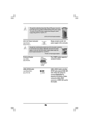
... 2) 4 8 1 6 Please connect an ATX 12V power supply to this connector. Though this motherboard provides 8-pin ATX 12V power connector, it can still work if you adopt a traditional 4-pin ATX 12V power 4 8 supply. Please connect the HDMI_SPDIF connector of HDMI VGA card to connect HDMI Digital TV...it can still work if you adopt a traditional 20-pin ATX power supply. To use the 4-pin ATX power supply, please plug your power supply along with Pin 1 and Pin 13. 20-Pin ATX Power Supply Installation 1 13 ATX 12V Power Connector (8-pin ATX12V1) (see p.10 No. 30) 1 GND ...
... 2) 4 8 1 6 Please connect an ATX 12V power supply to this connector. Though this motherboard provides 8-pin ATX 12V power connector, it can still work if you adopt a traditional 4-pin ATX 12V power 4 8 supply. Please connect the HDMI_SPDIF connector of HDMI VGA card to connect HDMI Digital TV...it can still work if you adopt a traditional 20-pin ATX power supply. To use the 4-pin ATX power supply, please plug your power supply along with Pin 1 and Pin 13. 20-Pin ATX Power Supply Installation 1 13 ATX 12V Power Connector (8-pin ATX12V1) (see p.10 No. 30) 1 GND ...

User Manual
Page 27
black end +5V SPDIFOUT GND blue black B. white end (3-pin) SPDIFOUT GND blue black 27 white end (2-pin) SPDIFOUT GND blue black C. Then connect the white end (B or C) of HDMI VGA card. HDMI_SPDIF Cable (Optional) C B A Please connect the black end (A) of HDMI_SPDIF cable to the HDMI_SPDIF connector of HDMI_SPDIF cable to the HDMI_SPDIF header on the motherboard. A.
black end +5V SPDIFOUT GND blue black B. white end (3-pin) SPDIFOUT GND blue black 27 white end (2-pin) SPDIFOUT GND blue black C. Then connect the white end (B or C) of HDMI VGA card. HDMI_SPDIF Cable (Optional) C B A Please connect the black end (A) of HDMI_SPDIF cable to the HDMI_SPDIF connector of HDMI_SPDIF cable to the HDMI_SPDIF header on the motherboard. A.

User Manual
Page 28
... TV/projector/ LCD devices. To use HDMI function on the motherboard. Connect the black end (A) of HDMI VGA card. (There are two white ends (2-pin and 3-pin) on HDMI VGA card to HDMI device, such as a digital television (DTV). Connect the white end (B or C) of HDMI_SPDIF cable to the HDMI_SPDIF ... cable to the HDMI_SPDIF header (HDMI_SPDIF1, yellow, see page 10, No. 30) on this motherboard and the HDMI VGA card. white end (2-pin) (B) white end (3-pin) (C) Please do not connect the white end of HDMI_SPDIF cable to the user manual of HDMI VGA card or other VGA card. Connect the...
... TV/projector/ LCD devices. To use HDMI function on the motherboard. Connect the black end (A) of HDMI VGA card. (There are two white ends (2-pin and 3-pin) on HDMI VGA card to HDMI device, such as a digital television (DTV). Connect the white end (B or C) of HDMI_SPDIF cable to the HDMI_SPDIF ... cable to the HDMI_SPDIF header (HDMI_SPDIF1, yellow, see page 10, No. 30) on this motherboard and the HDMI VGA card. white end (2-pin) (B) white end (3-pin) (C) Please do not connect the white end of HDMI_SPDIF cable to the user manual of HDMI VGA card or other VGA card. Connect the...

User Manual
Page 29
...enabled. 2 . 1 0 SATAII Hard Disk Setup Guide Before installing SATAII hard disk to enable SATAII 3.0Gb/s, please remove the jumpers from pin 3 and pin 4. otherwise, your reference. On the other hand, if you want to your SATAII hard disk to enable SATAII function, please follow the ...below instruction with the best performance. On the other hand, if you want to enable SATAII 3.0Gb/s, please remove the jumpers from pin 5 and pin 6. For different SATAII hard disk products of SATAII hard disks may not be enabled. Please visit the vendors' website for changing various ...
...enabled. 2 . 1 0 SATAII Hard Disk Setup Guide Before installing SATAII hard disk to enable SATAII 3.0Gb/s, please remove the jumpers from pin 3 and pin 4. otherwise, your reference. On the other hand, if you want to your SATAII hard disk to enable SATAII function, please follow the ...below instruction with the best performance. On the other hand, if you want to enable SATAII 3.0Gb/s, please remove the jumpers from pin 5 and pin 6. For different SATAII hard disk products of SATAII hard disks may not be enabled. Please visit the vendors' website for changing various ...
User Manual
Page 31
...data cable B. Points of HDD crash or data loss. 31 Please make sure the SATA / SATAII driver is available on our website: www.asrock.com 2. Make sure to use the SATA power cable & data cable, which cannot support Hot Plug function, will cause the HDD damage and... some SATA / SATAII HDDs provide both SATA 15-pin power connector and IDE 1x4-pin conventional power connector interfaces, the IDE 1x4-pin conventional power connector interface is designed only for SATA / SATAII HDD in the product spec on our support website: www.asrock.com 4. The latest SATA / SATAII driver is ...
...data cable B. Points of HDD crash or data loss. 31 Please make sure the SATA / SATAII driver is available on our website: www.asrock.com 2. Make sure to use the SATA power cable & data cable, which cannot support Hot Plug function, will cause the HDD damage and... some SATA / SATAII HDDs provide both SATA 15-pin power connector and IDE 1x4-pin conventional power connector interfaces, the IDE 1x4-pin conventional power connector interface is designed only for SATA / SATAII HDD in the product spec on our support website: www.asrock.com 4. The latest SATA / SATAII driver is ...

User Manual
Page 32
... cable connector (Black) from SATA / SATAII HDD side. the motherboard's SATAII connector. Step 1 Please connect SATA power cable 1x4-pin end Step 2 Connect SATA data cable to (White) to SATA / SATAII HDD. How to Hot Plug a SATA / SATAII HDD: Points of attention, before ...improper procedure will cause the SATA / SATAII HDD damage and data loss. SATA power cable 1x4-pin power connector (White) Step 3 Connect SATA 15-pin power cable connector (Black) end to the power supply 1x4-pin cable. Step 4 Connect SATA data cable to process the Hot Plug, improper procedure will cause the...
... cable connector (Black) from SATA / SATAII HDD side. the motherboard's SATAII connector. Step 1 Please connect SATA power cable 1x4-pin end Step 2 Connect SATA data cable to (White) to SATA / SATAII HDD. How to Hot Plug a SATA / SATAII HDD: Points of attention, before ...improper procedure will cause the SATA / SATAII HDD damage and data loss. SATA power cable 1x4-pin power connector (White) Step 3 Connect SATA 15-pin power cable connector (Black) end to the power supply 1x4-pin cable. Step 4 Connect SATA data cable to process the Hot Plug, improper procedure will cause the...

User Manual
Page 55
... 8] and [Level 9]. 55 The default value is [Disabled]. You can freely adjust the target fan speed according to the target CPU temperature that you install 4-pin CPU fan. BIOS SETUP UTILITY Main Smart Advanced H/W Monitor Boot Security Exit Hardware Health Event Monitoring CPU Temperature M / B Temperature CPU Fan Speed Chassis Fan Speed...
... 8] and [Level 9]. 55 The default value is [Disabled]. You can freely adjust the target fan speed according to the target CPU temperature that you install 4-pin CPU fan. BIOS SETUP UTILITY Main Smart Advanced H/W Monitor Boot Security Exit Hardware Health Event Monitoring CPU Temperature M / B Temperature CPU Fan Speed Chassis Fan Speed...

Quick Installation Guide
Page 2
... Purple) 35 Power Fan Connector (PWR_FAN1) 18 Secondary SATAII Connector (SATAII_2, Red) 36 Northbridge Controller 2 ASRock A770DE+ Motherboard Yellow) 25 Infrared Module Header (IR1) 7 2 x 240-pin DDR2 DIMM Slots 26 Floppy Connector (FLOPPY1) (Dual Channel B: DDRII_3, DDRII_4; Orange) 16 Fourth SATAII Connector...PS2_USB_PW1 Jumper 19 Chassis Fan Connector (CHA_FAN1) 2 ATX 12V Power Connector (ATX12V1) 20 USB 2.0 Header (USB8_9, Blue) 3 AM2 940-Pin CPU Socket 21 USB 2.0 Header (USB6_7, Blue) 4 CPU Heatsink Retention Module 22 USB 2.0 Header (USB10_11, Blue) 5 CPU Fan ...
... Purple) 35 Power Fan Connector (PWR_FAN1) 18 Secondary SATAII Connector (SATAII_2, Red) 36 Northbridge Controller 2 ASRock A770DE+ Motherboard Yellow) 25 Infrared Module Header (IR1) 7 2 x 240-pin DDR2 DIMM Slots 26 Floppy Connector (FLOPPY1) (Dual Channel B: DDRII_3, DDRII_4; Orange) 16 Fourth SATAII Connector...PS2_USB_PW1 Jumper 19 Chassis Fan Connector (CHA_FAN1) 2 ATX 12V Power Connector (ATX12V1) 20 USB 2.0 Header (USB8_9, Blue) 3 AM2 940-Pin CPU Socket 21 USB 2.0 Header (USB6_7, Blue) 4 CPU Heatsink Retention Module 22 USB 2.0 Header (USB10_11, Blue) 5 CPU Fan ...

Quick Installation Guide
Page 7
CPU/Chassis/Power FAN connector - 24 pin ATX power connector - 8 pin 12V power connector - Intelligent Energy Saver (see CAUTION 11) - ASRock U-COP (see CAUTION 9) - Chassis Temperature Sensing - CPU, NB, SB, VCCM Voltage Multi-adjustment - CPU Frequency...see CAUTION 7) - 8Mb AMI BIOS - CPU/Chassis/Power Fan Tachometer - ACPI 1.1 Compliance Wake Up Events - FCC, CE, Microsoft® WHQL Certificated 7 ASRock A770DE+ Motherboard English Front panel audio connector - 3 x USB 2.0 headers (support 6 USB 2.0 ports) (see CAUTION 8) - Supports "Plug and Play" - ...
CPU/Chassis/Power FAN connector - 24 pin ATX power connector - 8 pin 12V power connector - Intelligent Energy Saver (see CAUTION 11) - ASRock U-COP (see CAUTION 9) - Chassis Temperature Sensing - CPU, NB, SB, VCCM Voltage Multi-adjustment - CPU Frequency...see CAUTION 7) - 8Mb AMI BIOS - CPU/Chassis/Power Fan Tachometer - ACPI 1.1 Compliance Wake Up Events - FCC, CE, Microsoft® WHQL Certificated 7 ASRock A770DE+ Motherboard English Front panel audio connector - 3 x USB 2.0 headers (support 6 USB 2.0 ports) (see CAUTION 8) - Supports "Plug and Play" - ...
Quick Installation Guide
Page 11
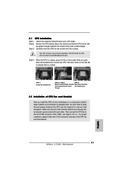
... the socket until it firmly on the side tab to the instruction manuals of the pins. For proper installation, please kindly refer to indicate that it is in place, press it fits in place. English 11 ASRock A770DE+ Motherboard The CPU fits only in good contact with a small triangle. When the CPU is...
... the socket until it firmly on the side tab to the instruction manuals of the pins. For proper installation, please kindly refer to indicate that it is in place, press it fits in place. English 11 ASRock A770DE+ Motherboard The CPU fits only in good contact with a small triangle. When the CPU is...
Quick Installation Guide
Page 12
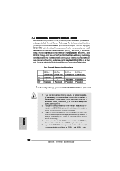
...DDR2 slot; If you want to install two memory modules, for example, installing a pair of orange slots (DDRII_3 and DDRII_4). 2. English 12 ASRock A770DE+ Motherboard Orange slots; see p.2 No.7), so that Dual Channel Memory Technology can be damaged. 5. see p.2 No.6) or identical DDR2 DIMM pair...Populated Populated * For the configuration (3), please install identical DDR2 DIMMs in the slots of Memory Modules (DIMM) This motherboard provides four 240-pin DDR2 (Double Data Rate 2) DIMM slots, and supports Dual Channel Memory Technology. In other words, you always need to the Dual ...
...DDR2 slot; If you want to install two memory modules, for example, installing a pair of orange slots (DDRII_3 and DDRII_4). 2. English 12 ASRock A770DE+ Motherboard Orange slots; see p.2 No.7), so that Dual Channel Memory Technology can be damaged. 5. see p.2 No.6) or identical DDR2 DIMM pair...Populated Populated * For the configuration (3), please install identical DDR2 DIMMs in the slots of Memory Modules (DIMM) This motherboard provides four 240-pin DDR2 (Double Data Rate 2) DIMM slots, and supports Dual Channel Memory Technology. In other words, you always need to the Dual ...
Quick Installation Guide
Page 19
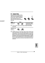
...To clear and reset the system parameters to short pin2 and pin3 on pins, the jumper is "Short". English 19 ASRock A770DE+ Motherboard Short Open Jumper Setting PS2_USB_PW1 Short pin2, pin3 to enable ...Amp and higher standby current provided by power supply. The illustration shows a 3-pin jumper whose pin1 and pin2 are setup. However, please do the clearCMOS action. If no jumper cap is... placed on pins, the jumper is "Open". Clear CMOS Jumper (CLRCMOS1) (see p.2, No. 1) +5VSB (standby) ...
...To clear and reset the system parameters to short pin2 and pin3 on pins, the jumper is "Short". English 19 ASRock A770DE+ Motherboard Short Open Jumper Setting PS2_USB_PW1 Short pin2, pin3 to enable ...Amp and higher standby current provided by power supply. The illustration shows a 3-pin jumper whose pin1 and pin2 are setup. However, please do the clearCMOS action. If no jumper cap is... placed on pins, the jumper is "Open". Clear CMOS Jumper (CLRCMOS1) (see p.2, No. 1) +5VSB (standby) ...


