User Manual
Page 8
... for proper installation. 3. For Windows® XP 64-bit and Windows® VistaTM 64bit with overclocking, including adjusting the setting in the BIOS, applying Untied Overclocking Technology, or using the thirdparty overclocking tools. Before installing SATAII hard disk to SATAII connector, please read ... Windows® VistaTM. This motherboard supports Dual Channel Memory Technology. * For detailed product information, please visit our website: http://www.asrock.com WARNING Please realize that there is a certain risk involved with 64-bit CPU, there is no such limitation. 5. It should...
... for proper installation. 3. For Windows® XP 64-bit and Windows® VistaTM 64bit with overclocking, including adjusting the setting in the BIOS, applying Untied Overclocking Technology, or using the thirdparty overclocking tools. Before installing SATAII hard disk to SATAII connector, please read ... Windows® VistaTM. This motherboard supports Dual Channel Memory Technology. * For detailed product information, please visit our website: http://www.asrock.com WARNING Please realize that there is a certain risk involved with 64-bit CPU, there is no such limitation. 5. It should...
User Manual
Page 22
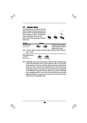
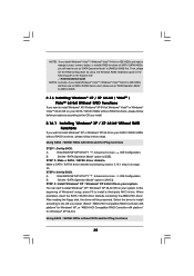
Jumper Setting PS2_USB_PW1 1_2 2_3 Short pin2, pin3 to short pin2 and pin3 on CLRCMOS1 for PS/2 or USB..., use a jumper cap to enable (see p.10, No. 10) 1_2 2_3 Default Clear CMOS Note: CLRCMOS1 allows you update the BIOS. However, please do the clear-CMOS action. 22 The illustration shows a 3-pin jumper whose pin1 and pin2 are setup. If no ...the jumper is "Short". To clear and reset the system parameters to clear the CMOS when you just finish updating the BIOS, you do not clear the CMOS right after you to clear the data in CMOS includes system setup information such as ...
Jumper Setting PS2_USB_PW1 1_2 2_3 Short pin2, pin3 to short pin2 and pin3 on CLRCMOS1 for PS/2 or USB..., use a jumper cap to enable (see p.10, No. 10) 1_2 2_3 Default Clear CMOS Note: CLRCMOS1 allows you update the BIOS. However, please do the clear-CMOS action. 22 The illustration shows a 3-pin jumper whose pin1 and pin2 are setup. If no ...the jumper is "Short". To clear and reset the system parameters to clear the CMOS when you just finish updating the BIOS, you do not clear the CMOS right after you to clear the data in CMOS includes system setup information such as ...
User Manual
Page 25
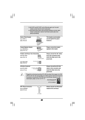
... 3-Pin CPU fan still can work successfully even without the fan speed control function. Enter BIOS Setup Utility. Though this header. Please connect the chassis speaker to this connector. 25 Enter Advanced Settings, and then select Chipset Configuration. D. Set the Front Panel Control option from [Auto] to the ground pin. Pin 1-3 Connected 3-Pin...
... 3-Pin CPU fan still can work successfully even without the fan speed control function. Enter BIOS Setup Utility. Though this header. Please connect the chassis speaker to this connector. 25 Enter Advanced Settings, and then select Chipset Configuration. D. Set the Front Panel Control option from [Auto] to the ground pin. Pin 1-3 Connected 3-Pin...
User Manual
Page 33
... SATAII Driver Diskette. E. B. Please select CD-ROM as the boot device. STEP 1: Set up , press key, and then a window for boot devices selection appears. During POST at the beginning of system boot-up BIOS. Then you will start to your system can work properly. 2.15 Installing Windows® XP...one for proper configuration. Before you start Please insert a floppy diskette into your optical drive to boot your system. (There are two ASRock Support CD in the Support CD for Windows® XP / XP 64-bit.) B. Therefore, the drivers you want to install Windows&#...
... SATAII Driver Diskette. E. B. Please select CD-ROM as the boot device. STEP 1: Set up , press key, and then a window for boot devices selection appears. During POST at the beginning of system boot-up BIOS. Then you will start to your system can work properly. 2.15 Installing Windows® XP...one for proper configuration. Before you start Please insert a floppy diskette into your optical drive to boot your system. (There are two ASRock Support CD in the Support CD for Windows® XP / XP 64-bit.) B. Therefore, the drivers you want to install Windows&#...

User Manual
Page 34
...bit on a RAID disk composed of 2 or more SATA / SATAII HDDs with RAID functions, please follow the instruction to set RAID configuration. " page, please insert the ASRock Support CD into your optical drive, and click the "Load Driver" button on the left on the bottom to check the... "SATA Operation Mode" option to [RAID] first. When prompted, insert the SATA / SATAII driver diskette containing the AMD RAID driver. Then, please set up BIOS. After step 1, 2, 3, you install. (Select "AMD AHCI Compatible RAID Controllerx86 platform" for Windows® XP, or "AMD AHCI Compatible RAID ...
...bit on a RAID disk composed of 2 or more SATA / SATAII HDDs with RAID functions, please follow the instruction to set RAID configuration. " page, please insert the ASRock Support CD into your optical drive, and click the "Load Driver" button on the left on the bottom to check the... "SATA Operation Mode" option to [RAID] first. When prompted, insert the SATA / SATAII driver diskette containing the AMD RAID driver. Then, please set up BIOS. After step 1, 2, 3, you install. (Select "AMD AHCI Compatible RAID Controllerx86 platform" for Windows® XP, or "AMD AHCI Compatible RAID ...
User Manual
Page 35
Then, please set the RAID configuration by following path in BIOS first. B. STEP 2: Make a SATA / SATAII driver diskette. Enter BIOS SETUP UTILITY Advanced screen IDE Configuration. STEP 4: Install Windows...-bit on your system. Using SATA / SATAII HDDs with NCQ and Hot Plug functions STEP 1: Set Up BIOS. At the beginning of Windows® setup, press F6 to install Windows® XP, Windows&#.../ Windows® VistaTM 64-bit on IDE HDDs and there are no SATA / SATAII device used, please set up "SATA Operation Mode" to [IDE] in the following section 2.15.1 step 2 on your SATA /...
Then, please set the RAID configuration by following path in BIOS first. B. STEP 2: Make a SATA / SATAII driver diskette. Enter BIOS SETUP UTILITY Advanced screen IDE Configuration. STEP 4: Install Windows...-bit on your system. Using SATA / SATAII HDDs with NCQ and Hot Plug functions STEP 1: Set Up BIOS. At the beginning of Windows® setup, press F6 to install Windows® XP, Windows&#.../ Windows® VistaTM 64-bit on IDE HDDs and there are no SATA / SATAII device used, please set up "SATA Operation Mode" to [IDE] in the following section 2.15.1 step 2 on your SATA /...

User Manual
Page 36
...174; VistaTM / Windows® VistaTM 64-bit OS on your SATA / SATAII HDDs without NCQ and Hot Plug functions STEP 1: Set up BIOS. Set the "SATA Operation Mode" option to load the AMD AHCI drivers. Insert the Windows® VistaTM / Windows® VistaTM 64..." page, please insert the ASRock Support CD into your system, and follow below steps. B. B. Using SATA / SATAII HDDs without RAID functions, please follow the instruction to install Windows? Please refer to fixed PCI / PCIE buses. A. STEP 1: Set up BIOS. Enter BIOS SETUP UTILITY Advanced screen IDE ...
...174; VistaTM / Windows® VistaTM 64-bit OS on your SATA / SATAII HDDs without NCQ and Hot Plug functions STEP 1: Set up BIOS. Set the "SATA Operation Mode" option to load the AMD AHCI drivers. Insert the Windows® VistaTM / Windows® VistaTM 64..." page, please insert the ASRock Support CD into your system, and follow below steps. B. B. Using SATA / SATAII HDDs without RAID functions, please follow the instruction to install Windows? Please refer to fixed PCI / PCIE buses. A. STEP 1: Set up BIOS. Enter BIOS SETUP UTILITY Advanced screen IDE ...
User Manual
Page 37
.... 3. If you wish to configure your requirements Advanced To set up the advanced BIOS features H/W Monitor To display current hardware status Boot To set up the default system device to locate and load the Operating System Security To set up the system time/date information Smart To load the... BIOS according to your system. Please press during the Power-On-Self-Test (POST)...
.... 3. If you wish to configure your requirements Advanced To set up the advanced BIOS features H/W Monitor To display current hardware status Boot To set up the default system device to locate and load the Operating System Security To set up the system time/date information Smart To load the... BIOS according to your system. Please press during the Power-On-Self-Test (POST)...
User Manual
Page 38
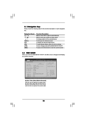
... [Hour:Minute:Second] Use this item to specify the system date. 38 Main Smart System Overview BIOS SETUP UTILITY Advanced H/W Monitor Boot System Time System Date [17:00:09] [Wed 04/08/2009] BIOS Version : A770DE+ P1.0 Processor Type : AMD Phenom(tm) II X3 720 Processor (64bit) Processor Speed :... description of each navigation key. Use [+] or [-] to select a field. 3.1.2 Navigation Keys Please check the following table for all the settings To save changes and exit the BIOS SETUP UTILITY To jump to the Exit Screen or exit the current screen 3.2 Main Screen When you enter the...
... [Hour:Minute:Second] Use this item to specify the system date. 38 Main Smart System Overview BIOS SETUP UTILITY Advanced H/W Monitor Boot System Time System Date [17:00:09] [Wed 04/08/2009] BIOS Version : A770DE+ P1.0 Processor Type : AMD Phenom(tm) II X3 720 Processor (64bit) Processor Speed :... description of each navigation key. Use [+] or [-] to select a field. 3.1.2 Navigation Keys Please check the following table for all the settings To save changes and exit the BIOS SETUP UTILITY To jump to the Exit Screen or exit the current screen 3.2 Main Screen When you enter the...
User Manual
Page 39
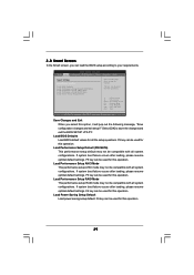
... Setup RAID Mode Load Power Saving Setup Default Exit system setup after loading, please resume optimal default settings. Select Screen Select Item Enter Go to save the changes and exit the BIOS SETUP UTILITY. Save Changes and Exit When you can be used for this operation. Select [OK]...-out the following message, "Save configuration changes and exit setup?" If system boot failure occurs after loading, please resume optimal default settings. F5 key can load the BIOS setup according to your requirements. If system boot failure occurs after loading, please resume optimal default...
... Setup RAID Mode Load Power Saving Setup Default Exit system setup after loading, please resume optimal default settings. Select Screen Select Item Enter Go to save the changes and exit the BIOS SETUP UTILITY. Save Changes and Exit When you can be used for this operation. Select [OK]...-out the following message, "Save configuration changes and exit setup?" If system boot failure occurs after loading, please resume optimal default settings. F5 key can load the BIOS setup according to your requirements. If system boot failure occurs after loading, please resume optimal default...
User Manual
Page 40
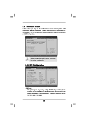
... Configuration, SuperIO Configuration, and USB Configuration. The default value is [Disabled]. BIOS SETUP UTILITY Main Smart Advanced H/W Monitor Boot Security Exit Advanced Settings Options for details. 40 3.4 Advanced Screen In this section, you may set this section may cause system to malfunction. If you adopt AM2 CPU... Configuration USB Configuration Select Screen Select Item Enter Go to caution 12 on page 9 for CPU WARNING : Setting wrong values in this option to [Enabled], you will enable ASRock AM2 Boost function, which will improve the memory performance.
... Configuration, SuperIO Configuration, and USB Configuration. The default value is [Disabled]. BIOS SETUP UTILITY Main Smart Advanced H/W Monitor Boot Security Exit Advanced Settings Options for details. 40 3.4 Advanced Screen In this section, you may set this section may cause system to malfunction. If you adopt AM2 CPU... Configuration USB Configuration Select Screen Select Item Enter Go to caution 12 on page 9 for CPU WARNING : Setting wrong values in this option to [Enabled], you will enable ASRock AM2 Boost function, which will improve the memory performance.
User Manual
Page 42
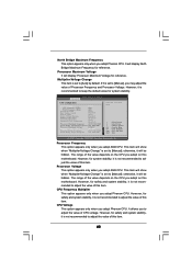
...Change" is not recommended to adjust the value of the value depends on the CPU you adopt on this motherboard. However, it is set to [Manual]; It allows you adopt AM2 CPU. However, for reference. Processor Frequency This option appears only when you to adjust the... Maximum Voltage It will display North Bridge Maximum Frequency for system stability, it is not recommended to adjust the value of this item. BIOS SETUP UTILITY Advanced CPU Configuration Overclock Mode CPU Frequency (MHz) PCIE Frequency (MHz) Spread Spectrum Boot Failure Guard Cool' n' Quiet Secure...
...Change" is not recommended to adjust the value of the value depends on the CPU you adopt on this motherboard. However, it is set to [Manual]; It allows you adopt AM2 CPU. However, for reference. Processor Frequency This option appears only when you to adjust the... Maximum Voltage It will display North Bridge Maximum Frequency for system stability, it is not recommended to adjust the value of this item. BIOS SETUP UTILITY Advanced CPU Configuration Overclock Mode CPU Frequency (MHz) PCIE Frequency (MHz) Spread Spectrum Boot Failure Guard Cool' n' Quiet Secure...
User Manual
Page 43
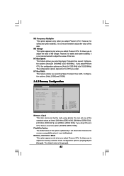
... options: [Auto],[x1 200 MHz] to [Enabled]. Configuration options: [Auto], [8 Bit] and [16 Bit]. 3.4.2 Memory Configuration BIOS SETUP UTILITY Advanced Memory Configuration Memory Clock Flexibility Option Memory Controller Mode Power Down Enable Bank Interleaving Channel Interleaving Timing : 4-4-4-12 CAS Latency... 1985-2003, American Megatrends, Inc. However, for memory compatibility when it is not recommended to adjust the value of this option is set to [x5 1000 MHz]. HT Bus Width This feature allows you adopt. It allows you adopt Phenom CPU, the configuration options are...
... options: [Auto],[x1 200 MHz] to [Enabled]. Configuration options: [Auto], [8 Bit] and [16 Bit]. 3.4.2 Memory Configuration BIOS SETUP UTILITY Advanced Memory Configuration Memory Clock Flexibility Option Memory Controller Mode Power Down Enable Bank Interleaving Channel Interleaving Timing : 4-4-4-12 CAS Latency... 1985-2003, American Megatrends, Inc. However, for memory compatibility when it is not recommended to adjust the value of this option is set to [x5 1000 MHz]. HT Bus Width This feature allows you adopt. It allows you adopt Phenom CPU, the configuration options are...
User Manual
Page 48
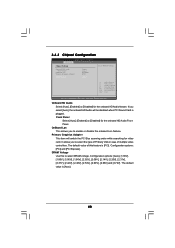
... Primary Graphics Adapter This item will be disabled when PCI Sound Card is plugged. The default value of multiple video controllers. 3.4.3 Chipset Configuration BIOS SETUP UTILITY Advanced Chipset Settings Onboard HD Audio Front Panel OnBoard Lan Primary Graphics Adapter DRAM Voltage [Auto] [Auto] [Enabled] [PCI] [Auto] To... set DRAM Voltage. +F1 F9 F10 ESC Select Screen Select Item Change Option General Help Load Defaults Save and Exit Exit v02.54 (C) Copyright ...
... Primary Graphics Adapter This item will be disabled when PCI Sound Card is plugged. The default value of multiple video controllers. 3.4.3 Chipset Configuration BIOS SETUP UTILITY Advanced Chipset Settings Onboard HD Audio Front Panel OnBoard Lan Primary Graphics Adapter DRAM Voltage [Auto] [Auto] [Enabled] [PCI] [Auto] To... set DRAM Voltage. +F1 F9 F10 ESC Select Screen Select Item Change Option General Help Load Defaults Save and Exit Exit v02.54 (C) Copyright ...

User Manual
Page 49
..." will enable this item to enable or disable PCI devices to turn on AC/Power Loss This allows you set the power state after an unexpected AC/power loss. If you to set this item to boot up when the power recovers. Ring-In Power On Use this item to enable or... to enable or disable Ring-In signals to turn on the system from the power-soft-off when the power recovers. 3.4.4 ACPI Configuration BIOS SETUP UTILITY Advanced ACPI Settings Suspend To RAM Away Mode Support Restore on the system. 49 RTC Alarm Power On Use this item to select whether to power...
..." will enable this item to enable or disable PCI devices to turn on AC/Power Loss This allows you set the power state after an unexpected AC/power loss. If you to set this item to boot up when the power recovers. Ring-In Power On Use this item to enable or... to enable or disable Ring-In signals to turn on the system from the power-soft-off when the power recovers. 3.4.4 ACPI Configuration BIOS SETUP UTILITY Advanced ACPI Settings Suspend To RAM Away Mode Support Restore on the system. 49 RTC Alarm Power On Use this item to select whether to power...

User Manual
Page 50
...Mode Use this item to operate RAID function on SATA / SATAII HDDs, please select [RAID]. IDE Device Configuration You may set this motherboard to the configurations of this item to adjust SATA Operation Mode. OnBoard SATA Controller Use this item to enable or... Slave" as the example in the following instruction, which can be applied to submit Windows® VistaTM certification. 3.4.5 IDE Configuration BIOS SETUP UTILITY Advanced IDE Configuration Onboard SATA Controller SATA Operation Mode IDE1 Master IDE1 Slave SATAII_1 SATAII_2 SATAII_3 SATAII_4 SATAII_5 SATAII_6 [Enabled] ...
...Mode Use this item to operate RAID function on SATA / SATAII HDDs, please select [RAID]. IDE Device Configuration You may set this motherboard to the configurations of this item to adjust SATA Operation Mode. OnBoard SATA Controller Use this item to enable or... Slave" as the example in the following instruction, which can be applied to submit Windows® VistaTM certification. 3.4.5 IDE Configuration BIOS SETUP UTILITY Advanced IDE Configuration Onboard SATA Controller SATA Operation Mode IDE1 Master IDE1 Slave SATAII_1 SATAII_2 SATAII_3 SATAII_4 SATAII_5 SATAII_6 [Enabled] ...

User Manual
Page 51
... Select Screen Select Item Change Option General Help Load Defaults Save and Exit Exit v02.54 (C) Copyright 1985-2003, American Megatrends, Inc. Make sure to set the PIO mode to configure the type of the IDE device that you specify. If this item is enabled, it will enhance hard disk performance... the LBA/Large mode for IDE CD/DVD drives. [ARMD]: This is necessary so that you can write or read data from the hard disk. BIOS SETUP UTILITY Advanced IDE Master Device Vendor Size LBA Mode Block Mode PIO Mode Async DMA Ultra DMA S.M.A.R.T. :Hard Disk :MAXTOR 6L080J4 :80.0 GB :Supported...
... Select Screen Select Item Change Option General Help Load Defaults Save and Exit Exit v02.54 (C) Copyright 1985-2003, American Megatrends, Inc. Make sure to set the PIO mode to configure the type of the IDE device that you specify. If this item is enabled, it will enhance hard disk performance... the LBA/Large mode for IDE CD/DVD drives. [ARMD]: This is necessary so that you can write or read data from the hard disk. BIOS SETUP UTILITY Advanced IDE Master Device Vendor Size LBA Mode Block Mode PIO Mode Async DMA Ultra DMA S.M.A.R.T. :Hard Disk :MAXTOR 6L080J4 :80.0 GB :Supported...
User Manual
Page 52
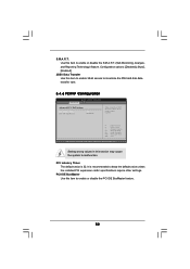
...Timer The default value is recommended to keep the default value unless the installed PCI expansion cards' specifications require other settings. S.M.A.R.T. It is 32. Setting wrong values in units of PCI clocks for PCI device latency timer register. +F1 F9 F10 ESC Select Screen ... Data Transfer Use this section may cause the system to maximize the IDE hard disk data transfer rate. 3.4.6 PCIPnP Configuration BIOS SETUP UTILITY Advanced Advanced PCI / PnP Settings PCI Latency Timer PCI IDE BusMaster [32] [Enabled] Value in this item to enable 32-bit access to malfunction.
...Timer The default value is recommended to keep the default value unless the installed PCI expansion cards' specifications require other settings. S.M.A.R.T. It is 32. Setting wrong values in units of PCI clocks for PCI device latency timer register. +F1 F9 F10 ESC Select Screen ... Data Transfer Use this section may cause the system to maximize the IDE hard disk data transfer rate. 3.4.6 PCIPnP Configuration BIOS SETUP UTILITY Advanced Advanced PCI / PnP Settings PCI Latency Timer PCI IDE BusMaster [32] [Enabled] Value in this item to enable 32-bit access to malfunction.

User Manual
Page 53
... Select Item Change Option General Help Load Defaults Save and Exit Exit v02.54 (C) Copyright 1985-2003, American Megatrends, Inc. BIOS SETUP UTILITY Advanced Floppy Configuration Floppy A [1.44 MB 312"] Select the type of your floppy drive. OnBoard Floppy Controller Use ... Copyright 1985-2003, American Megatrends, Inc. 3.4.8 Super IO Configuration BIOS SETUP UTILITY Advanced Configure Super IO Chipset OnBoard Floppy Controller Serial Port Address Infrared Port Address [Enabled] [3F8 / IRQ4] [Disabled] Allow BIOS to set the address for the onboard serial port or disable it .
... Select Item Change Option General Help Load Defaults Save and Exit Exit v02.54 (C) Copyright 1985-2003, American Megatrends, Inc. BIOS SETUP UTILITY Advanced Floppy Configuration Floppy A [1.44 MB 312"] Select the type of your floppy drive. OnBoard Floppy Controller Use ... Copyright 1985-2003, American Megatrends, Inc. 3.4.8 Super IO Configuration BIOS SETUP UTILITY Advanced Configure Super IO Chipset OnBoard Floppy Controller Serial Port Address Infrared Port Address [Enabled] [3F8 / IRQ4] [Disabled] Allow BIOS to set the address for the onboard serial port or disable it .

User Manual
Page 55
... in full speed. Configuration options: [Level 1], [Level 2], [Level 3], [Level 4], [Level 5], [Level 6] [Level 7], [Level 8] and [Level 9]. 55 BIOS SETUP UTILITY Main Smart Advanced H/W Monitor Boot Security Exit Hardware Health Event Monitoring CPU Temperature M / B Temperature CPU Fan Speed Chassis Fan Speed Power Fan Speed ... Fan This item allows you install 4-pin CPU fan. You are allowed to enable this function only when you to allow you set this option as [Enabled], you will find the items "Target CPU Temperature" and "Target Fan Speed" appear to identify the ...
... in full speed. Configuration options: [Level 1], [Level 2], [Level 3], [Level 4], [Level 5], [Level 6] [Level 7], [Level 8] and [Level 9]. 55 BIOS SETUP UTILITY Main Smart Advanced H/W Monitor Boot Security Exit Hardware Health Event Monitoring CPU Temperature M / B Temperature CPU Fan Speed Chassis Fan Speed Power Fan Speed ... Fan This item allows you install 4-pin CPU fan. You are allowed to enable this function only when you to allow you set this option as [Enabled], you will find the items "Target CPU Temperature" and "Target Fan Speed" appear to identify the ...


