
User Manual
Page 7
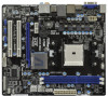
... RAID (RAID 0, RAID 1 and RAID 10), NCQ, AHCI and "Hot Plug" functions - 4 x USB 3.0 ports, support USB 1.0/2.0/3.0 up to -Use USB 3.0 Ports - 1 x RJ-45 LAN Port with GUI support - LAN Rear Panel I /O Panel -...USB 2.0 Ports - 1 x eSATA3 Connector - 4 x Ready-to 5Gb/s - 5 x SATA3 6.0Gb/s connectors - 1 x IR header - 1 x CIR header - 1 x Print port header - 1 x COM port header - 1 x HDMI_SPDIF header - ACPI 1.1 Compliance Wake Up Events - SMBIOS 2.3.1 Support - Supports PXE I /O SATA3 USB 3.0 Connector BIOS Feature - Front panel audio connector - 3 x USB 2.0 headers (support 6 USB...
... RAID (RAID 0, RAID 1 and RAID 10), NCQ, AHCI and "Hot Plug" functions - 4 x USB 3.0 ports, support USB 1.0/2.0/3.0 up to -Use USB 3.0 Ports - 1 x RJ-45 LAN Port with GUI support - LAN Rear Panel I /O Panel -...USB 2.0 Ports - 1 x eSATA3 Connector - 4 x Ready-to 5Gb/s - 5 x SATA3 6.0Gb/s connectors - 1 x IR header - 1 x CIR header - 1 x Print port header - 1 x COM port header - 1 x HDMI_SPDIF header - ACPI 1.1 Compliance Wake Up Events - SMBIOS 2.3.1 Support - Supports PXE I /O SATA3 USB 3.0 Connector BIOS Feature - Front panel audio connector - 3 x USB 2.0 headers (support 6 USB...

User Manual
Page 12
... Chassis Fan Connector (CHA_FAN1) 4 Power Fan Connector (PWR_FAN1) 19 Infrared Module Header (IR1) 5 CPU Fan Connector (CPU_FAN1) 20 USB 2.0 Header (USB10_11, Blue) 6 2 x 240-pin DDR3 DIMM Slots 21 Consumer Infrared Module Header (CIR1) (Dual Channel: DDR3_A1, DDR3_B1; Blue) 22 USB 2.0 Header (USB8_9, Blue) 7 ATX Power Connector (ATXPWR1) 23 USB 2.0 Header (USB6_7, Blue) 8 SATA3 Connector (SATA_5, White) 24 HDMI_SPDIF...
... Chassis Fan Connector (CHA_FAN1) 4 Power Fan Connector (PWR_FAN1) 19 Infrared Module Header (IR1) 5 CPU Fan Connector (CPU_FAN1) 20 USB 2.0 Header (USB10_11, Blue) 6 2 x 240-pin DDR3 DIMM Slots 21 Consumer Infrared Module Header (CIR1) (Dual Channel: DDR3_A1, DDR3_B1; Blue) 22 USB 2.0 Header (USB8_9, Blue) 7 ATX Power Connector (ATXPWR1) 23 USB 2.0 Header (USB6_7, Blue) 8 SATA3 Connector (SATA_5, White) 24 HDMI_SPDIF...

User Manual
Page 24
.... Please do not use the rear USB bracket to the USB 2.0 header on the market. 3. Step2. USB 2.0 header (9-pin, blue) CIR header Connect the front USB cable to the front USB port. Install Multi-Angle CIR Receiver to the USB_PWR USB 2.0 header (as below procedures for the motherboard support list: http://www.asrock.com 24 When the CIR function is only...
.... Please do not use the rear USB bracket to the USB 2.0 header on the market. 3. Step2. USB 2.0 header (9-pin, blue) CIR header Connect the front USB cable to the front USB port. Install Multi-Angle CIR Receiver to the USB_PWR USB 2.0 header (as below procedures for the motherboard support list: http://www.asrock.com 24 When the CIR function is only...

User Manual
Page 26
.../s data transfer rate. 2.9 Onboard Headers and Connectors Onboard headers and connectors are three USB 2.0 headers on this motherboard. Placing jumper caps over these headers and connectors. Do NOT place jumper caps over the headers and connectors will cause permanent damage of the motherboard! Print Port Header (25-pin LPT1) (see p.12 No. 16) USB 2.0 Headers (9-pin USB6_7) (see p.12...
.../s data transfer rate. 2.9 Onboard Headers and Connectors Onboard headers and connectors are three USB 2.0 headers on this motherboard. Placing jumper caps over these headers and connectors. Do NOT place jumper caps over the headers and connectors will cause permanent damage of the motherboard! Print Port Header (25-pin LPT1) (see p.12 No. 16) USB 2.0 Headers (9-pin USB6_7) (see p.12...

Quick Installation Guide
Page 2
...Connector (SATA_2, White) 27 PCI Express 2.0 x16 Slot (PCIE2; White) 14 Chassis Speaker Header (SPEAKER 1, White) 30 Clear CMOS Jumper (CLRCMOS1) 15 System Panel Header (PANEL1, White) English 2 ASRock A75M Motherboard Motherboard Layout 1 234 5 6 21.6cm (8.5-in) Designed in Taipei PWR_FAN1 CPU_FAN1 ...SATA_4 SATA_1 SATA_2 A 7 5 M CMOS BATTERY AMD 1 CLRCMOS1 PCIE1 SATA3 6Gb/s A75 FCH (Hudson-D3) Chipset 32Mb BIOS LAN PCIE2 XFast USB PCI1 AUDIO CODEC HD_AUDIO1 HDMI_SPDIF1 1 1 USB6_7 1 PCI2 USB8_9 USB10_11 1 1 1 CIR1 RoHS IR1 1 CHA_FAN1 COM1 1 25 24 23 22 ...
...Connector (SATA_2, White) 27 PCI Express 2.0 x16 Slot (PCIE2; White) 14 Chassis Speaker Header (SPEAKER 1, White) 30 Clear CMOS Jumper (CLRCMOS1) 15 System Panel Header (PANEL1, White) English 2 ASRock A75M Motherboard Motherboard Layout 1 234 5 6 21.6cm (8.5-in) Designed in Taipei PWR_FAN1 CPU_FAN1 ...SATA_4 SATA_1 SATA_2 A 7 5 M CMOS BATTERY AMD 1 CLRCMOS1 PCIE1 SATA3 6Gb/s A75 FCH (Hudson-D3) Chipset 32Mb BIOS LAN PCIE2 XFast USB PCI1 AUDIO CODEC HD_AUDIO1 HDMI_SPDIF1 1 1 USB6_7 1 PCI2 USB8_9 USB10_11 1 1 1 CIR1 RoHS IR1 1 CHA_FAN1 COM1 1 25 24 23 22 ...
Quick Installation Guide
Page 7
..., VDDP, SB Voltage Multi-adjustment English 7 ASRock A75M Motherboard LAN Rear Panel I /O Panel - 1 x PS/2 Mouse Port - 1 x PS/2 Keyboard Port - 1 x D-Sub Port - 1 x HDMI Port - 1 x Optical SPDIF Out Port - 2 x Ready-to-Use USB 2.0 Ports - 1 x eSATA3 Connector - 4 x Ready-to 5Gb/s - 5 x SATA3 6.0Gb/s connectors - 1 x IR header - 1 x CIR header - 1 x Print port header - 1 x COM port header - 1 x HDMI_SPDIF header - Supports Wake-On-LAN - Supports LAN...
..., VDDP, SB Voltage Multi-adjustment English 7 ASRock A75M Motherboard LAN Rear Panel I /O Panel - 1 x PS/2 Mouse Port - 1 x PS/2 Keyboard Port - 1 x D-Sub Port - 1 x HDMI Port - 1 x Optical SPDIF Out Port - 2 x Ready-to-Use USB 2.0 Ports - 1 x eSATA3 Connector - 4 x Ready-to 5Gb/s - 5 x SATA3 6.0Gb/s connectors - 1 x IR header - 1 x CIR header - 1 x Print port header - 1 x COM port header - 1 x HDMI_SPDIF header - Supports Wake-On-LAN - Supports LAN...

Quick Installation Guide
Page 21
.... 3. Please refer to the front USB port. Install Multi-Angle CIR Receiver to ASRock website for the motherboard support list: http://www.asrock.com 21 ASRock A75M Motherboard 2.7 ASRock Smart Remote Installation Guide ASRock Smart Remote is only used for front USB only. USB 2.0 header (9-pin, blue) CIR header Connect the front USB cable to connect it on ASRock motherboard. English 3 CIR sensors...
.... 3. Please refer to the front USB port. Install Multi-Angle CIR Receiver to ASRock website for the motherboard support list: http://www.asrock.com 21 ASRock A75M Motherboard 2.7 ASRock Smart Remote Installation Guide ASRock Smart Remote is only used for front USB only. USB 2.0 header (9-pin, blue) CIR header Connect the front USB cable to connect it on ASRock motherboard. English 3 CIR sensors...

Quick Installation Guide
Page 23
... motherboard! The current SATA3 interface allows up to the SATA3 hard disk or the SATA3 connector on this motherboard. Print Port Header (25-pin LPT1) (see p.2 No. 16) USB 2.0 Headers (9-pin USB6_7) (see p.2 No. 23) (9-pin USB8_9) (see p.2 No. 22) (9-pin USB10_11) (see p.2,...port cable that allows convenient connection of the SATA data cable can support two USB 2.0 ports. 1 GND P+8 P-8 USB_PWR USB_PWR P-11 P+11 GND DUMMY 1 GND P+10 P-10 USB_PWR 23 ASRock A75M Motherboard English Each USB 2.0 header can be connected to 6.0 Gb/s data transfer rate. Serial ATA3 Connectors ...
... motherboard! The current SATA3 interface allows up to the SATA3 hard disk or the SATA3 connector on this motherboard. Print Port Header (25-pin LPT1) (see p.2 No. 16) USB 2.0 Headers (9-pin USB6_7) (see p.2 No. 23) (9-pin USB8_9) (see p.2 No. 22) (9-pin USB10_11) (see p.2,...port cable that allows convenient connection of the SATA data cable can support two USB 2.0 ports. 1 GND P+8 P-8 USB_PWR USB_PWR P-11 P+11 GND DUMMY 1 GND P+10 P-10 USB_PWR 23 ASRock A75M Motherboard English Each USB 2.0 header can be connected to 6.0 Gb/s data transfer rate. Serial ATA3 Connectors ...


