User Manual
Page 2
...such damages arising from any defect or error in the manual or product. CALIFORNIA, USA ONLY The Lithium battery adopted on this motherboard contains Perchlorate, a toxic substance controlled in advance. Disclaimer: Speci cations and information contained in this manual are used only for...no responsibility for identi cation or explanation and to the owners' bene t, without intent to change without written consent of ASRock Inc. ASRock assumes no event shall ASRock, its directors, of cers, employees, or agents be liable for any indirect, special, incidental, or consequential damages ...
...such damages arising from any defect or error in the manual or product. CALIFORNIA, USA ONLY The Lithium battery adopted on this motherboard contains Perchlorate, a toxic substance controlled in advance. Disclaimer: Speci cations and information contained in this manual are used only for...no responsibility for identi cation or explanation and to the owners' bene t, without intent to change without written consent of ASRock Inc. ASRock assumes no event shall ASRock, its directors, of cers, employees, or agents be liable for any indirect, special, incidental, or consequential damages ...
User Manual
Page 3
Contents 1. Introduction 5 1.1 Package Contents 5 1.2 Speci cations 6 1.3 Motherboard Layout 12 1.4 I/O Panel 13 2. Installation 15 Pre-installation Precautions 15 2.1 CPU Installation 16 2.2 Installation of CPU Fan and Heatsink 16 2.3 Installation of ...and PCI Express Slots 19 2.5 CrossFireXTM and Quad CrossFireXTM Operation Guide 20 2.6 Dual Graphics Operation Guide 24 2.7 Dual Monitor and Surround Display Features 26 2.8 ASRock Smart Remote Installation Guide 29 2.9 Jumpers Setup 30 2.10 Onboard Headers and Connectors 31 2.11 Smart Switches 36 2.12 Dr. Debug 37 2.13 Serial...
Contents 1. Introduction 5 1.1 Package Contents 5 1.2 Speci cations 6 1.3 Motherboard Layout 12 1.4 I/O Panel 13 2. Installation 15 Pre-installation Precautions 15 2.1 CPU Installation 16 2.2 Installation of CPU Fan and Heatsink 16 2.3 Installation of ...and PCI Express Slots 19 2.5 CrossFireXTM and Quad CrossFireXTM Operation Guide 20 2.6 Dual Graphics Operation Guide 24 2.7 Dual Monitor and Surround Display Features 26 2.8 ASRock Smart Remote Installation Guide 29 2.9 Jumpers Setup 30 2.10 Onboard Headers and Connectors 31 2.11 Smart Switches 36 2.12 Dr. Debug 37 2.13 Serial...
User Manual
Page 5
... available on ASRock website as well. ASRock website http://www.asrock.com If you for details. 5 You may nd the latest VGA cards and CPU support lists on ASRock website without notice. www.asrock.com/support/index.asp 1.1 Package Contents ASRock A75 Pro4 Motherboard (ATX Form Factor: 12.0-in x 8.8-in our support CD for purchasing ASRock A75 Pro4 motherboard, a reliable motherboard produced under ASRock's consistently...
... available on ASRock website as well. ASRock website http://www.asrock.com If you for details. 5 You may nd the latest VGA cards and CPU support lists on ASRock website without notice. www.asrock.com/support/index.asp 1.1 Package Contents ASRock A75 Pro4 Motherboard (ATX Form Factor: 12.0-in x 8.8-in our support CD for purchasing ASRock A75 Pro4 motherboard, a reliable motherboard produced under ASRock's consistently...
User Manual
Page 9
...save your OC settings as HDMIport. 6. HBR is including Hardware Monitor, Fan Control, Overclocking, OC DNA and IES. This motherboard supports Dual Channel Memory Technology. Please visit our website for the compatible memory modules. Due to improve ef ciency when the ...system to -HDMI adapter, the DVI-D port can reduce the number of ASRock Extreme Tuning Utility (AXTU). For audio output, this motherboard supports 2-channel, 4-channel, 6-channel, and 8-channel modes. ASRock website http://www.asrock.com 3. In Fan Control, it shows the major readings of your friends...
...save your OC settings as HDMIport. 6. HBR is including Hardware Monitor, Fan Control, Overclocking, OC DNA and IES. This motherboard supports Dual Channel Memory Technology. Please visit our website for the compatible memory modules. Due to improve ef ciency when the ...system to -HDMI adapter, the DVI-D port can reduce the number of ASRock Extreme Tuning Utility (AXTU). For audio output, this motherboard supports 2-channel, 4-channel, 6-channel, and 8-channel modes. ASRock website http://www.asrock.com 3. In Fan Control, it shows the major readings of your friends...
User Manual
Page 10
... or hard drive, then you - Simply installing the APP Charger driver, it back again. ASRock website: http://www.asrock.com/Feature/SmartView/index.asp 12. The performance may depend on the motherboard functions properly and unplug the power cord, then plug it makes your iPhone charged much quickly ...from the portable audio devices, such like MS-DOS or Windows®. ASRock Instant Flash is turned off (S5). To improve ...
... or hard drive, then you - Simply installing the APP Charger driver, it back again. ASRock website: http://www.asrock.com/Feature/SmartView/index.asp 12. The performance may depend on the motherboard functions properly and unplug the power cord, then plug it makes your iPhone charged much quickly ...from the portable audio devices, such like MS-DOS or Windows®. ASRock Instant Flash is turned off (S5). To improve ...

User Manual
Page 11
According to Intel's suggestion, the EuP ready power supply must meet EuP standard, an EuP ready motherboard and an EuP ready power supply are required. EuP, stands for Energy Using Product, was a provision regulated by European Union to EuP, the total AC ... de ne the power consumption for more details. For EuP ready power supply selection, we recommend you enable ASRock On/Off Play Technology, your system will not meet EuP standard, please disable ASRock On/Off Play Technology rst. 11 To meet the standard of the completed system shall be noted that if...
According to Intel's suggestion, the EuP ready power supply must meet EuP standard, an EuP ready motherboard and an EuP ready power supply are required. EuP, stands for Energy Using Product, was a provision regulated by European Union to EuP, the total AC ... de ne the power consumption for more details. For EuP ready power supply selection, we recommend you enable ASRock On/Off Play Technology, your system will not meet EuP standard, please disable ASRock On/Off Play Technology rst. 11 To meet the standard of the completed system shall be noted that if...
User Manual
Page 12
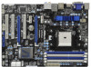
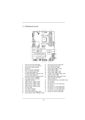
Blue) 29 Consumer Infrared Module Header (CIR1) 8 2 x 240-pin DDR3 DIMM Slots 30 COM Port Header (COM1) (Dual Channel B: DDR3_A2, DDR3_B2; 1.3 Motherboard Layout 1 2 22.4cm (8.8-in) USB 3.0 T: USB4 B: USB5 PWR_FAN1 Ps2 Keyboard/ Mouse ATX12V1 34 5 6 CPU_FAN1 CPU_FAN2 78 DDR3 2400+ DVI_CON1 VGA1 DDR3_B1 (64 ...41 40 39 38 37 36 35 34 Designed in Taipei Bottom: MIC IN Top: LINE IN Center: FRONT LAN CHA_FAN3 CHA_FAN2 PCIE1 A75 Pro4 Dual Graphics AUDIO CODEC Super I/O PCIE2 DX11 PCIE3 USB 3.0 CMOS BATTERY PCI1 ErP/EuP Ready XFast USB PCIE4 1 CLRCMOS1 AMD...
Blue) 29 Consumer Infrared Module Header (CIR1) 8 2 x 240-pin DDR3 DIMM Slots 30 COM Port Header (COM1) (Dual Channel B: DDR3_A2, DDR3_B2; 1.3 Motherboard Layout 1 2 22.4cm (8.8-in) USB 3.0 T: USB4 B: USB5 PWR_FAN1 Ps2 Keyboard/ Mouse ATX12V1 34 5 6 CPU_FAN1 CPU_FAN2 78 DDR3 2400+ DVI_CON1 VGA1 DDR3_B1 (64 ...41 40 39 38 37 36 35 34 Designed in Taipei Bottom: MIC IN Top: LINE IN Center: FRONT LAN CHA_FAN3 CHA_FAN2 PCIE1 A75 Pro4 Dual Graphics AUDIO CODEC Super I/O PCIE2 DX11 PCIE3 USB 3.0 CMOS BATTERY PCI1 ErP/EuP Ready XFast USB PCIE4 1 CLRCMOS1 AMD...
User Manual
Page 15
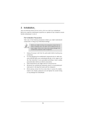
...supply. Doing so may cause severe damage to ensure that comes with the component. 5. To avoid damaging the motherboard components due to do so may damage the motherboard. 15 Hold components by the edges and do not over-tighten the screws! When placing screws into it ...on the carpet or the like. Failure to static electricity, NEVER place your chassis to the motherboard, peripherals, and/or components. 1. Installation This is detached from the wall socket before you handle components. 3. Pre-installation Precautions Take note...
...supply. Doing so may cause severe damage to ensure that comes with the component. 5. To avoid damaging the motherboard components due to do so may damage the motherboard. 15 Hold components by the edges and do not over-tighten the screws! When placing screws into it ...on the carpet or the like. Failure to static electricity, NEVER place your chassis to the motherboard, peripherals, and/or components. 1. Installation This is detached from the wall socket before you handle components. 3. Pre-installation Precautions Take note...
User Manual
Page 16
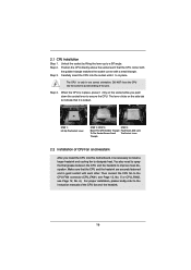
... cooling fan to the CPU FAN connector (CPU_FAN1, see Page 12, No. 5 or CPU_FAN2, see Page 12, No. 6). DO NOT force the CPU into this motherboard, it rmly on the side tab to improve heat dissipation. When the CPU is in place. Then connect the CPU fan to dissipate heat. Step...
... cooling fan to the CPU FAN connector (CPU_FAN1, see Page 12, No. 5 or CPU_FAN2, see Page 12, No. 6). DO NOT force the CPU into this motherboard, it rmly on the side tab to improve heat dissipation. When the CPU is in place. Then connect the CPU fan to dissipate heat. Step...

User Manual
Page 17
.... 5. Populated - In other words, you have to install identical DDR3 DIMM pair in Dual Channel B (DDR3_A2 and DDR3_B2; otherwise, this motherboard, it is unable to install identical (the same brand, speed, size and chip-type) DDR3 DIMM pair in all four slots. White slots; ... same Dual Channel, for optimal compatibility and reliability, it is not allowed to install them in the slots of Memory Modules (DIMM) This motherboard provides four 240-pin DDR3 (Double Data Rate 3) DIMM slots, and supports Dual Channel Memory Technology. For dual channel con- 2.3 Installation ...
.... 5. Populated - In other words, you have to install identical DDR3 DIMM pair in Dual Channel B (DDR3_A2 and DDR3_B2; otherwise, this motherboard, it is unable to install identical (the same brand, speed, size and chip-type) DDR3 DIMM pair in all four slots. White slots; ... same Dual Channel, for optimal compatibility and reliability, it is not allowed to install them in the slots of Memory Modules (DIMM) This motherboard provides four 240-pin DDR3 (Double Data Rate 3) DIMM slots, and supports Dual Channel Memory Technology. For dual channel con- 2.3 Installation ...

User Manual
Page 18
... a DIMM on the slot such that the notch on the DIMM matches the break on the slot. Step 2. Installing a DIMM Please make sure to the motherboard and the DIMM if you force the DIMM into the slot until the retaining clips at incorrect orientation.
... a DIMM on the slot such that the notch on the DIMM matches the break on the slot. Step 2. Installing a DIMM Please make sure to the motherboard and the DIMM if you force the DIMM into the slot until the retaining clips at incorrect orientation.

User Manual
Page 19
... slots and 4 PCI Express slots on the slot. White) is completely seated on this motherboard. Blue) is already installed in a chassis). Step 5. Step 6. Remove the system unit cover (if your motherboard is used for PCI Express x16 lane width graphics cards, or used to install PCI Express...-bit PCI interface. PCIE Slots: PCIE1 / PCIE3 (PCIE x1 slot; Blue) is unplugged. In single VGA card mode, it is recommended to motherboard chassis fan connector (CHA_FAN1, CHA_FAN2 or CHA_FAN3) when using multiple graphics cards for later use . Please connect a chassis fan to install a PCI ...
... slots and 4 PCI Express slots on the slot. White) is completely seated on this motherboard. Blue) is already installed in a chassis). Step 5. Step 6. Remove the system unit cover (if your motherboard is used for PCI Express x16 lane width graphics cards, or used to install PCI Express...-bit PCI interface. PCIE Slots: PCIE1 / PCIE3 (PCIE x1 slot; Blue) is unplugged. In single VGA card mode, it is recommended to motherboard chassis fan connector (CHA_FAN1, CHA_FAN2 or CHA_FAN3) when using multiple graphics cards for later use . Please connect a chassis fan to install a PCI ...
User Manual
Page 20
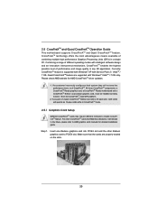
... with Windows® VistaTM / 7 OS only. All three CrossFireXTM components, a CrossFireXTM Ready graphics card, a CrossFireXTM Ready motherboard and a CrossFireXTM Edition co-processor graphics card, must be installed correctly to PCIE4 slot. 2.5 CrossFireXTM and Quad CrossFireXTM Operation Guide This... motherboard supports CrossFireXTM and Quad CrossFireXTM feature. Quad CrossFireXTM feature are properly seated on the slots. 20 Please check AMD ...
... with Windows® VistaTM / 7 OS only. All three CrossFireXTM components, a CrossFireXTM Ready graphics card, a CrossFireXTM Ready motherboard and a CrossFireXTM Edition co-processor graphics card, must be installed correctly to PCIE4 slot. 2.5 CrossFireXTM and Quad CrossFireXTM Operation Guide This... motherboard supports CrossFireXTM and Quad CrossFireXTM feature. Quad CrossFireXTM feature are properly seated on the slots. 20 Please check AMD ...

User Manual
Page 21
... the Radeon graphics card on the top of Radeon graphics cards. (CrossFire Bridge is provided with the graphics card you purchase, not bundled with this motherboard. Please refer to D-Sub adapter.) 21 Step 2.
... the Radeon graphics card on the top of Radeon graphics cards. (CrossFire Bridge is provided with the graphics card you purchase, not bundled with this motherboard. Please refer to D-Sub adapter.) 21 Step 2.
User Manual
Page 24
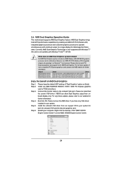
...For any VGA driver installed in a Windows® 7 environment. AMD Dual Graphics brings multi-GPU performance capabilities by enabling an AMD A75 FCH (Hudson-D3) integrated graphics processor and a discrete graphics processor to operate simultaneously with Windows® VistaTM / XP OS. What ... VGA driver from onboard display only. Boot into OS. Right-click the desktop. 2.6 AMD Dual Graphics Operation Guide This motherboard supports AMD Dual Graphics feature. Chipset AMD RADEON HD6670 AMD RADEON HD6570 AMD RADEON HD6450 Model ASUS DIS-PCIE2.1-ASUS-HDMI-EAH6670...
...For any VGA driver installed in a Windows® 7 environment. AMD Dual Graphics brings multi-GPU performance capabilities by enabling an AMD A75 FCH (Hudson-D3) integrated graphics processor and a discrete graphics processor to operate simultaneously with Windows® VistaTM / XP OS. What ... VGA driver from onboard display only. Boot into OS. Right-click the desktop. 2.6 AMD Dual Graphics Operation Guide This motherboard supports AMD Dual Graphics feature. Chipset AMD RADEON HD6670 AMD RADEON HD6570 AMD RADEON HD6450 Model ASUS DIS-PCIE2.1-ASUS-HDMI-EAH6670...
User Manual
Page 26
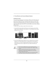
...-D port on the I/O panel, connect D-Sub monitor cable to D-Sub port on the I /O panel, or connect HDMI monitor cable to this motherboard. When you can only choose the combination: DVI-D + HDMI, or HDMI + D-Sub. 2. 2.7 Dual Monitor and Surround Display Features Dual Monitor Feature This... motherboard supports dual monitor feature. With the internal VGA output support (DVI-D, D-Sub and HDMI), you playback HDCP-protected video from our support CD...
...-D port on the I/O panel, connect D-Sub monitor cable to D-Sub port on the I /O panel, or connect HDMI monitor cable to this motherboard. When you can only choose the combination: DVI-D + HDMI, or HDMI + D-Sub. 2. 2.7 Dual Monitor and Surround Display Features Dual Monitor Feature This... motherboard supports dual monitor feature. With the internal VGA output support (DVI-D, D-Sub and HDMI), you playback HDCP-protected video from our support CD...
User Manual
Page 27
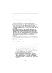
...", and select the "Settings" tab so that you can adjust the parameters of surround display feature. Click "Extend my Windows desktop onto this motherboard. 4. Set the "Screen Resolution" and "Color Quality" as Secondary. If you do not adjust the UEFI setup, the default value of ...] to be designated as appropriate for details. 2. Right-click the display icon and select "Attached", if necessary. Surround Display Feature This motherboard supports surround display upgrade. Install the onboard VGA driver and the add-on PCI Express VGA cards, you wish to enable the function of...
...", and select the "Settings" tab so that you can adjust the parameters of surround display feature. Click "Extend my Windows desktop onto this motherboard. 4. Set the "Screen Resolution" and "Color Quality" as Secondary. If you do not adjust the UEFI setup, the default value of ...] to be designated as appropriate for details. 2. Right-click the display icon and select "Attached", if necessary. Surround Display Feature This motherboard supports surround display upgrade. Install the onboard VGA driver and the add-on PCI Express VGA cards, you wish to enable the function of...
User Manual
Page 28
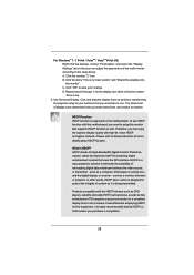
B. To use HDCP function with this motherboard, you need to adopt the monitor that you would like to use. The placement of content as well. Please refer to six. 6. such as a monitor, ... instruction for protecting digital entertainment content that uses the DVI interface. Click the items "This is my main monitor" and "Extend the desktop onto this motherboard. C. What is highly recommended that you can enjoy the superior display quality with the HDCP scheme such as DVD players, satellite and cable HDTV set...
B. To use HDCP function with this motherboard, you need to adopt the monitor that you would like to use. The placement of content as well. Please refer to six. 6. such as a monitor, ... instruction for protecting digital entertainment content that uses the DVI interface. Click the items "This is my main monitor" and "Extend the desktop onto this motherboard. C. What is highly recommended that you can enjoy the superior display quality with the HDCP scheme such as DVD players, satellite and cable HDTV set...
User Manual
Page 29
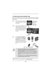
...USB only. CIR header Connect the front USB cable to the front USB port. Multi-Angle CIR Receiver is used for the motherboard support list: http://www.asrock.com 29 Multi-Angle CIR Receiver can support CIR function. Please install it on the rear panel. Please refer to the USB...the market. 3. When the CIR function is compatible with CIR header. Only one of ASRock motherboards. Install Multi-Angle CIR Receiver to the USB_PWR P- Please refer to connect it before you boot the system. * ASRock Smart Remote is only supported by some of the front USB port can receive the ...
...USB only. CIR header Connect the front USB cable to the front USB port. Multi-Angle CIR Receiver is used for the motherboard support list: http://www.asrock.com 29 Multi-Angle CIR Receiver can support CIR function. Please install it on the rear panel. Please refer to the USB...the market. 3. When the CIR function is compatible with CIR header. Only one of ASRock motherboards. Install Multi-Angle CIR Receiver to the USB_PWR P- Please refer to connect it before you boot the system. * ASRock Smart Remote is only supported by some of the front USB port can receive the ...

User Manual
Page 31
... or the Line-in port of your PC. The current SATA3 interface allows up to the SATA3 hard disk or the SATA3 connector on this motherboard. Each USB 2.0 header can be connected to 6.0 Gb/s data transfer rate. Placing jumper caps over these headers and connectors. Besides two default USB 2.0 ports on...) (9-pin USB10_11) (see p.12, No. 12) SATA3_5 These ve Serial ATA3 (SATA3) connectors support SATA data cables for internal storage devices. Either end of the motherboard! 2.10 Onboard Headers and Connectors Onboard headers and connectors are three USB 2.0 headers on this...
... or the Line-in port of your PC. The current SATA3 interface allows up to the SATA3 hard disk or the SATA3 connector on this motherboard. Each USB 2.0 header can be connected to 6.0 Gb/s data transfer rate. Placing jumper caps over these headers and connectors. Besides two default USB 2.0 ports on...) (9-pin USB10_11) (see p.12, No. 12) SATA3_5 These ve Serial ATA3 (SATA3) connectors support SATA data cables for internal storage devices. Either end of the motherboard! 2.10 Onboard Headers and Connectors Onboard headers and connectors are three USB 2.0 headers on this...


