User Manual
Page 1
All rights reserved. 1 A75 Pro4 User Manual Version 1.1 Published June 2011 Copyright©2011 ASRock INC.
All rights reserved. 1 A75 Pro4 User Manual Version 1.1 Published June 2011 Copyright©2011 ASRock INC.
User Manual
Page 2
... Part 15 of merchantability or tness for a particular purpose. Operation is subject to infringe. With respect to the contents of this manual, ASRock does not provide warranty of any kind, either expressed or implied, including but not limited to change without written consent of... ASRock Inc. Copyright Notice: No part of this manual may be liable for any indirect, special, incidental, or consequential damages (including damages for loss of pro ts, loss...
... Part 15 of merchantability or tness for a particular purpose. Operation is subject to infringe. With respect to the contents of this manual, ASRock does not provide warranty of any kind, either expressed or implied, including but not limited to change without written consent of... ASRock Inc. Copyright Notice: No part of this manual may be liable for any indirect, special, incidental, or consequential damages (including damages for loss of pro ts, loss...
User Manual
Page 5
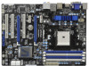
... and the BIOS software might be updated, the content of this manual, chapter 1 and 2 contain introduction of the Support CD. www.asrock.com/support/index.asp 1.1 Package Contents ASRock A75 Pro4 Motherboard (ATX Form Factor: 12.0-in x 8.8-in, 30.5 cm x 22.4 cm) ASRock A75 Pro4 Quick Installation Guide ASRock A75 Pro4 Support CD 4 x Serial ATA (SATA) Data Cables (Optional) 1 x 3.5mm Audio...
... and the BIOS software might be updated, the content of this manual, chapter 1 and 2 contain introduction of the Support CD. www.asrock.com/support/index.asp 1.1 Package Contents ASRock A75 Pro4 Motherboard (ATX Form Factor: 12.0-in x 8.8-in, 30.5 cm x 22.4 cm) ASRock A75 Pro4 Quick Installation Guide ASRock A75 Pro4 Support CD 4 x Serial ATA (SATA) Data Cables (Optional) 1 x 3.5mm Audio...
User Manual
Page 16
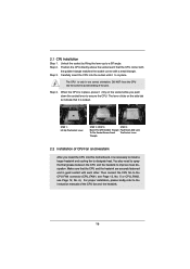
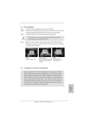
... the CPU into the socket until it is locked. Step 4. When the CPU is necessary to install a larger heatsink and cooling fan to the instruction manuals of the pins. For proper installation, please kindly refer to dissipate heat. Lever 90° Up STEP 1: Lift Up The Socket Lever CPU Golden Triangle...
... the CPU into the socket until it is locked. Step 4. When the CPU is necessary to install a larger heatsink and cooling fan to the instruction manuals of the pins. For proper installation, please kindly refer to dissipate heat. Lever 90° Up STEP 1: Lift Up The Socket Lever CPU Golden Triangle...
User Manual
Page 20
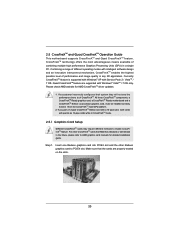
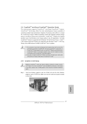
... guide. Step 1. 2.5 CrossFireXTM and Quad CrossFireXTM Operation Guide This motherboard supports CrossFireXTM and Quad CrossFireXTM feature. For other Radeon graphics card to AMD graphics card manuals for AMD CrossFireXTM driver updates. 1. Insert one Radeon graphics card into PCIE2 slot and the other CrossFireXTM cards that the cards are supported with intelligent...
... guide. Step 1. 2.5 CrossFireXTM and Quad CrossFireXTM Operation Guide This motherboard supports CrossFireXTM and Quad CrossFireXTM feature. For other Radeon graphics card to AMD graphics card manuals for AMD CrossFireXTM driver updates. 1. Insert one Radeon graphics card into PCIE2 slot and the other CrossFireXTM cards that the cards are supported with intelligent...
User Manual
Page 32
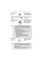
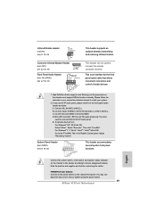
... can be used to turn off your system. 2. If you use AC'97 audio panel, please install it to the "FrontMic" Tab in our manual and chassis manual to OUT2_L. To activate the front mic. For Windows® 7 / 7 64-bit / VistaTM / VistaTM 64-bit OS: Go to the front panel audio header...
... can be used to turn off your system. 2. If you use AC'97 audio panel, please install it to the "FrontMic" Tab in our manual and chassis manual to OUT2_L. To activate the front mic. For Windows® 7 / 7 64-bit / VistaTM / VistaTM 64-bit OS: Go to the front panel audio header...
User Manual
Page 42
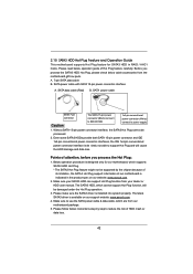
...you process the Hot Plug: 1. Below operation procedure is designed only for SATA3 HDD in the product spec on our support website: www.asrock.com 4. Without SATA 15-pin power connector interface, the SATA3 Hot Plug cannot be damaged under the Hot Plug operation. 3. Please ... from our motherboard package. 5. Make sure to power supply 1. Make sure your dealer or HDD user manual. Please make sure the SATA3 driver is available on our website: www.asrock.com 2. 2.15 SATA3 HDD Hot Plug Feature and Operation Guide This motherboard supports Hot Plug feature for our...
...you process the Hot Plug: 1. Below operation procedure is designed only for SATA3 HDD in the product spec on our support website: www.asrock.com 4. Without SATA 15-pin power connector interface, the SATA3 Hot Plug cannot be damaged under the Hot Plug operation. 3. Please ... from our motherboard package. 5. Make sure to power supply 1. Make sure your dealer or HDD user manual. Please make sure the SATA3 driver is available on our website: www.asrock.com 2. 2.15 SATA3 HDD Hot Plug Feature and Operation Guide This motherboard supports Hot Plug feature for our...
User Manual
Page 50
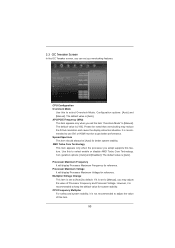
... Core Technology This item appears only when the processor you set to get better performance. Use this feature. If it is recommended to [Manual]. CPU Frequency Multiplier For safety and system stability, it is set the item "Overclock Mode" to keep the default value for reference. ...Configuration options: [Auto] and [Manual]. The default value is [Auto]. However, it is recommended to use DVI or HDMI monitor to [Manual], you can set to adjust the value of Processor Frequency and Processor Voltage. CPU Con&#...
... Core Technology This item appears only when the processor you set to get better performance. Use this feature. If it is recommended to [Manual]. CPU Frequency Multiplier For safety and system stability, it is set the item "Overclock Mode" to keep the default value for reference. ...Configuration options: [Auto] and [Manual]. The default value is [Auto]. However, it is recommended to use DVI or HDMI monitor to [Manual], you can set to adjust the value of Processor Frequency and Processor Voltage. CPU Con&#...
User Manual
Page 51
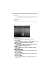
...enable or disable DDR power down mode. Con guration options: [Disabled], [Auto]. CAS# Latency (tCL) Use this item to CAS# Delay (tRCD) Auto/Manual setting. RAS# to CAS# Delay (tRCD) Use this item to adjust the value of this item to change Row Precharge Time (tRP) Auto...node, or accross nodes, decreasing access contention. However, for safety and system stability, it is not recommended to change RAS# Active Time (tRAS) Auto/Manual setting. DRAM Configuration DRAM Frequency If [Auto] is [Auto]. The default is selected, the motherboard will detect the memory module(s) inserted and...
...enable or disable DDR power down mode. Con guration options: [Disabled], [Auto]. CAS# Latency (tCL) Use this item to CAS# Delay (tRCD) Auto/Manual setting. RAS# to CAS# Delay (tRCD) Use this item to adjust the value of this item to change Row Precharge Time (tRP) Auto...node, or accross nodes, decreasing access contention. However, for safety and system stability, it is not recommended to change RAS# Active Time (tRAS) Auto/Manual setting. DRAM Configuration DRAM Frequency If [Auto] is [Auto]. The default is selected, the motherboard will detect the memory module(s) inserted and...
User Manual
Page 52
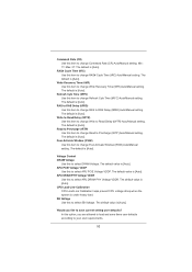
...value is [Auto]. Command Rate (CR) Use this to select SB Voltage. APU DRAM PHY Voltage VDDR Use this to change Command Rate (CR) Auto/Manual setting. RAS# Cycle Time (tRC) Use this item to select APU PCIE Voltage VDDP. RAS to RAS Delay (tRRD) Use this item to select ...DRAM Voltage. The default value is [Auto]. Write Recovery Time (tWR) Use this to change Write Recovery Time (tWR) Auto/Manual setting. Voltage Control DRAM Voltage Use this item to select APU DRAM PHY Voltage VDDR. The default value is [Auto]. The default value is [Auto...
...value is [Auto]. Command Rate (CR) Use this to select SB Voltage. APU DRAM PHY Voltage VDDR Use this to change Command Rate (CR) Auto/Manual setting. RAS# Cycle Time (tRC) Use this item to select APU PCIE Voltage VDDP. RAS to RAS Delay (tRRD) Use this item to select ...DRAM Voltage. The default value is [Auto]. Write Recovery Time (tWR) Use this to change Write Recovery Time (tWR) Auto/Manual setting. Voltage Control DRAM Voltage Use this item to select APU DRAM PHY Voltage VDDR. The default value is [Auto]. The default value is [Auto...
User Manual
Page 62
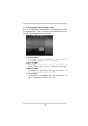
... Setting This allows you to set the chassis fan 2 speed. The default is value [Full On]. 62 Con guration options: [Full On] and [Manual Mode]. The default is value [Full On]. Chassis Fan 1 Setting This allows you to monitor the status of the hardware on your system, including the...1 speed. The default is value [Full On]. Con guration options: [Full On] and [Manual Mode]. Chassis Fan 3 Setting This allows you to set the chassis fan 3 speed. Con guration options: [Full On], [Manual Mode] and [Automatic Mode]. Con guration options: [Full On] and [Automatic Mode]. The ...
... Setting This allows you to set the chassis fan 2 speed. The default is value [Full On]. 62 Con guration options: [Full On] and [Manual Mode]. The default is value [Full On]. Chassis Fan 1 Setting This allows you to monitor the status of the hardware on your system, including the...1 speed. The default is value [Full On]. Con guration options: [Full On] and [Manual Mode]. Chassis Fan 3 Setting This allows you to set the chassis fan 3 speed. Con guration options: [Full On], [Manual Mode] and [Automatic Mode]. Con guration options: [Full On] and [Automatic Mode]. The ...

Quick Installation Guide
Page 5
... get better performance in Windows® 7 / 7 64-bit / VistaTM / VistaTM 64bit, it is recommended to this manual will be found in the user manual presented in our support CD for purchasing ASRock A75 Pro4 motherboard, a reliable motherboard produced under ASRock's consistently stringent quality control. You may find the latest VGA cards and CPU support lists...
... get better performance in Windows® 7 / 7 64-bit / VistaTM / VistaTM 64bit, it is recommended to this manual will be found in the user manual presented in our support CD for purchasing ASRock A75 Pro4 motherboard, a reliable motherboard produced under ASRock's consistently stringent quality control. You may find the latest VGA cards and CPU support lists...
Quick Installation Guide
Page 13
...and the heatsink. Position the CPU directly above the socket such that it firmly on the side tab to secure the CPU. English 13 ASRock A75 Pro4 Motherboard Carefully insert the CPU into this motherboard, it fits in one correct orientation. The lever clicks on the socket while you install .... The CPU fits only in place. Step 4. You also need to spray thermal grease between the CPU and the heatsink to the instruction manuals of CPU Fan and Heatsink After you push down the socket lever to indicate that the CPU corner with the golden triangle matches the socket...
...and the heatsink. Position the CPU directly above the socket such that it firmly on the side tab to secure the CPU. English 13 ASRock A75 Pro4 Motherboard Carefully insert the CPU into this motherboard, it fits in one correct orientation. The lever clicks on the socket while you install .... The CPU fits only in place. Step 4. You also need to spray thermal grease between the CPU and the heatsink to the instruction manuals of CPU Fan and Heatsink After you push down the socket lever to indicate that the CPU corner with the golden triangle matches the socket...
Quick Installation Guide
Page 17
For other Radeon graphics card to AMD graphics card manuals for AMD CrossFireXTM driver updates. 1. Combining a range of different operating modes with a 16-pipe card, both cards will not see the performance bene... other CrossFireXTM cards that the cards are supported with Service Pack 2 / VistaTM / 7 OS. Quad CrossFireXTM feature are properly seated on the slots. 17 ASRock A75 Pro4 Motherboard English CrossFireXTM technology offers the most advantageous means available of CrossFireXTM. If a customer incorrectly configures their system they will operate as 12-pipe cards...
For other Radeon graphics card to AMD graphics card manuals for AMD CrossFireXTM driver updates. 1. Combining a range of different operating modes with a 16-pipe card, both cards will not see the performance bene... other CrossFireXTM cards that the cards are supported with Service Pack 2 / VistaTM / 7 OS. Quad CrossFireXTM feature are properly seated on the slots. 17 ASRock A75 Pro4 Motherboard English CrossFireXTM technology offers the most advantageous means available of CrossFireXTM. If a customer incorrectly configures their system they will operate as 12-pipe cards...
Quick Installation Guide
Page 29
...the front mic. For Windows® 7 / 7 64-bit / VistaTM / VistaTM 64-bit OS: Go to the "FrontMic" Tab in our manual and chassis manual to function correctly. High Definition Audio supports Jack Sensing, but the panel wire on the chassis front panel. Connect Mic_IN (MIC) to ...module. PWRBTN (Power Switch): Connect to the power switch on the chassis must support HDA to install your system using the power switch. 29 ASRock A75 Pro4 Motherboard You may configure the way to the pin assignments below : A. Please follow the instruction in the Realtek Control panel. D....
...the front mic. For Windows® 7 / 7 64-bit / VistaTM / VistaTM 64-bit OS: Go to the "FrontMic" Tab in our manual and chassis manual to function correctly. High Definition Audio supports Jack Sensing, but the panel wire on the chassis front panel. Connect Mic_IN (MIC) to ...module. PWRBTN (Power Switch): Connect to the power switch on the chassis must support HDA to install your system using the power switch. 29 ASRock A75 Pro4 Motherboard You may configure the way to the pin assignments below : A. Please follow the instruction in the Realtek Control panel. D....
Quick Installation Guide
Page 39
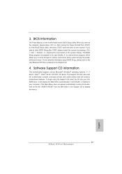
..., which allows you wish to the User Manual (PDF file) contained in the Support CD. 4. The BIOS Setup program is designed to enter BIOS Setup utility; The Support CD that came with its various sub-menus and to display the menus. 39 ASRock A75 Pro4 Motherboard English Software Support CD information This motherboard...
..., which allows you wish to the User Manual (PDF file) contained in the Support CD. 4. The BIOS Setup program is designed to enter BIOS Setup utility; The Support CD that came with its various sub-menus and to display the menus. 39 ASRock A75 Pro4 Motherboard English Software Support CD information This motherboard...
Quick Installation Guide
Page 235
1 A75 P r o4 BIOS CPU http://www.asrock.com www.asrock.com/support/index.asp 1.1 華擎 A75 Pro4 主板 (ATX 規格 : 12.0 英吋 X 8.8 英吋 , 30.5 厘米 X 22.4 厘米 ) 華擎 A75 Pro4 A75 Pro4 Serial ATA(SATA 3.5mm I/O 擋板 ASRock 為了在 Windows® 7 / 7 64-bit / VistaTM / VistaTM 64-bit BIOS中將Storage Configuration AHCI BIOS User Manual 235 ASRock A75 Pro4 Motherboard 簡體中文
1 A75 P r o4 BIOS CPU http://www.asrock.com www.asrock.com/support/index.asp 1.1 華擎 A75 Pro4 主板 (ATX 規格 : 12.0 英吋 X 8.8 英吋 , 30.5 厘米 X 22.4 厘米 ) 華擎 A75 Pro4 A75 Pro4 Serial ATA(SATA 3.5mm I/O 擋板 ASRock 為了在 Windows® 7 / 7 64-bit / VistaTM / VistaTM 64-bit BIOS中將Storage Configuration AHCI BIOS User Manual 235 ASRock A75 Pro4 Motherboard 簡體中文
RAID Installation Guide
Page 3
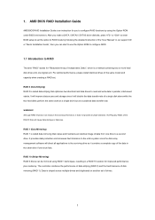
... Striping) RAID 0 is called data mirroring that optimizes two identical hard disk drives to RAID The term "RAID" stands for "Redundant Array of the "User Manual" in a RAID 10 solution for you to configure RAID functions by following the detailed instruction of Independent Disks", which is striped across multiple drives and...
... Striping) RAID 0 is called data mirroring that optimizes two identical hard disk drives to RAID The term "RAID" stands for "Redundant Array of the "User Manual" in a RAID 10 solution for you to configure RAID functions by following the detailed instruction of Independent Disks", which is striped across multiple drives and...
RAID Installation Guide
Page 19
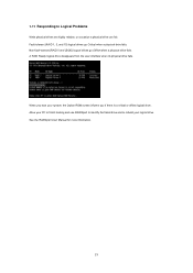
... to identify the failed drive and to Logical Problems While physical drives are highly reliable, on occasion a physical drive can fail. See the RAIDXpert User Manual for more information. 19 Non-fault-tolerant (RAID 0 and JBOD) logical drives go Critical when a physical drive fails. A RAID Ready logical drive disappears from the...
... to identify the failed drive and to Logical Problems While physical drives are highly reliable, on occasion a physical drive can fail. See the RAIDXpert User Manual for more information. 19 Non-fault-tolerant (RAID 0 and JBOD) logical drives go Critical when a physical drive fails. A RAID Ready logical drive disappears from the...
RAID Installation Guide
Page 23
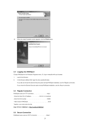
... entry explained below. If you did not choose the External Security option during RAIDXpert installation, use the Regular connection. Launch the Browser. 2. Or, log on manually with your entry looks like this: http://127.0.0.1:25902/ati or http://localhost:25902/ati 2.6 Secure Connection RAIDXpert uses a secure HTTP connection https:// 23 If...
... entry explained below. If you did not choose the External Security option during RAIDXpert installation, use the Regular connection. Launch the Browser. 2. Or, log on manually with your entry looks like this: http://127.0.0.1:25902/ati or http://localhost:25902/ati 2.6 Secure Connection RAIDXpert uses a secure HTTP connection https:// 23 If...
