User Manual
Page 5
...User Manual" in , 30.5 cm x 22.4 cm) ASRock A75 Pro4 Quick Installation Guide ASRock A75 Pro4 Support CD 4 x Serial ATA (SATA) Data Cables (Optional) 1 x 3.5mm Audio Cable (Optional) 1 x I/O Panel Shield ASRock Reminds You... In case any modi cations of the motherboard ... please refer to AHCI mode. 1. www.asrock.com/support/index.asp 1.1 Package Contents ASRock A75 Pro4 Motherboard (ATX Form Factor: 12.0-in x 8.8-in our support CD for purchasing ASRock A75 Pro4 motherboard, a reliable motherboard produced under ASRock's consistently stringent quality control. Introduction Thank you...
...User Manual" in , 30.5 cm x 22.4 cm) ASRock A75 Pro4 Quick Installation Guide ASRock A75 Pro4 Support CD 4 x Serial ATA (SATA) Data Cables (Optional) 1 x 3.5mm Audio Cable (Optional) 1 x I/O Panel Shield ASRock Reminds You... In case any modi cations of the motherboard ... please refer to AHCI mode. 1. www.asrock.com/support/index.asp 1.1 Package Contents ASRock A75 Pro4 Motherboard (ATX Form Factor: 12.0-in x 8.8-in our support CD for purchasing ASRock A75 Pro4 motherboard, a reliable motherboard produced under ASRock's consistently stringent quality control. Introduction Thank you...
User Manual
Page 6
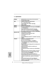
All Solid Capacitor design - AMD A75 FCH (Hudson-D3) - Support DDR3 2400+(OC)/1866/1600/1333/1066/ 800 non-ECC, un-buffered memory (see CAUTION 3) - 2 x PCI Express 2.0 x16 slots (PCIE2 @ x16 ..., DVI-D and HDMI (see CAUTION 1) - 4 x DDR3 DIMM slots - Supports HDCP function with DVI and HDMI ports - shared memory 512MB (see CAUTION 6) - V4 + 1 Power Phase Design - ATX Form Factor: 12.0-in x 8.8-in, 30.5 cm x 22.4 cm -
All Solid Capacitor design - AMD A75 FCH (Hudson-D3) - Support DDR3 2400+(OC)/1866/1600/1333/1066/ 800 non-ECC, un-buffered memory (see CAUTION 3) - 2 x PCI Express 2.0 x16 slots (PCIE2 @ x16 ..., DVI-D and HDMI (see CAUTION 1) - 4 x DDR3 DIMM slots - Supports HDCP function with DVI and HDMI ports - shared memory 512MB (see CAUTION 6) - V4 + 1 Power Phase Design - ATX Form Factor: 12.0-in x 8.8-in, 30.5 cm x 22.4 cm -
User Manual
Page 7
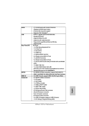
... - 1 x Power LED header - Supports LAN Cable Detection - Premium Blu-ray audio support - Realtek RTL8111E - Supports Wake-On-LAN - CPU/Chassis/Power FAN connector - 24 pin ATX power connector - 8 pin 12V power connector - PCIE x1 Gigabit LAN 10/100/1000 Mb/s - Front panel audio connector - 3 x USB 2.0 headers (support 6 USB 2.0 ports) - 1 x Dr. Debug...
... - 1 x Power LED header - Supports LAN Cable Detection - Premium Blu-ray audio support - Realtek RTL8111E - Supports Wake-On-LAN - CPU/Chassis/Power FAN connector - 24 pin ATX power connector - 8 pin 12V power connector - PCIE x1 Gigabit LAN 10/100/1000 Mb/s - Front panel audio connector - 3 x USB 2.0 headers (support 6 USB 2.0 ports) - 1 x Dr. Debug...
User Manual
Page 12
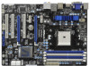
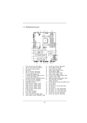
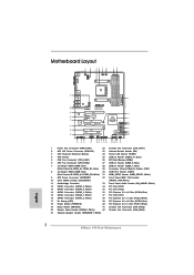
... 39 38 37 36 35 34 Designed in Taipei Bottom: MIC IN Top: LINE IN Center: FRONT LAN CHA_FAN3 CHA_FAN2 PCIE1 A75 Pro4 Dual Graphics AUDIO CODEC Super I/O PCIE2 DX11 PCIE3 USB 3.0 CMOS BATTERY PCI1 ErP/EuP Ready XFast USB PCIE4 1 CLRCMOS1 AMD... PCI Express 2.0 x1 Slot (PCIE3; Blue) 18 Power Switch (PWRBTN) 40 PCI Express 2.0 x1 Slot (PCIE1; White) 31 HDMI_SPDIF Header (HDMI_SPDIF1, White) 9 ATX Power Connector (ATXPWR1) 32 Front Panel IEEE 1394 Header 10 Clear CMOS Jumper (CLRCMOS1) (FRONT_1394, White) 11 Southbridge Controller 33 Front Panel Audio Header (HD_AUDIO1...
... 39 38 37 36 35 34 Designed in Taipei Bottom: MIC IN Top: LINE IN Center: FRONT LAN CHA_FAN3 CHA_FAN2 PCIE1 A75 Pro4 Dual Graphics AUDIO CODEC Super I/O PCIE2 DX11 PCIE3 USB 3.0 CMOS BATTERY PCI1 ErP/EuP Ready XFast USB PCIE4 1 CLRCMOS1 AMD... PCI Express 2.0 x1 Slot (PCIE3; Blue) 18 Power Switch (PWRBTN) 40 PCI Express 2.0 x1 Slot (PCIE1; White) 31 HDMI_SPDIF Header (HDMI_SPDIF1, White) 9 ATX Power Connector (ATXPWR1) 32 Front Panel IEEE 1394 Header 10 Clear CMOS Jumper (CLRCMOS1) (FRONT_1394, White) 11 Southbridge Controller 33 Front Panel Audio Header (HD_AUDIO1...
User Manual
Page 15
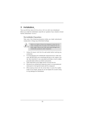
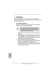
... motherboard, peripherals, and/or components. 1. Whenever you install or remove any component, ensure that the power is switched off or the power cord is an ATX form factor (12.0-in x 8.8-in the bag that the motherboard ts into the screw holes to secure the motherboard to do not touch the ICs. 4.
... motherboard, peripherals, and/or components. 1. Whenever you install or remove any component, ensure that the power is switched off or the power cord is an ATX form factor (12.0-in x 8.8-in the bag that the motherboard ts into the screw holes to secure the motherboard to do not touch the ICs. 4.
User Manual
Page 29
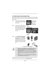
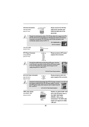
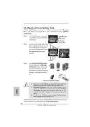
... Remote Installation Guide ASRock Smart Remote is only used for front USB only. Please refer to the USB_PWR P- Please make GND DUMMY sure the wire assignments and the pin assignments are matched correctly. 1 23 45 GND IRTX IRRX ATX+5VSB Step3. Install Multi-Angle CIR Receiver to... the other port will remain USB function. 2. Please install it before you boot the system. * ASRock Smart Remote is used for ASRock motherboard with most of ASRock motherboards. Only one of ASRock Smart Remote. The Multi-Angle ...
... Remote Installation Guide ASRock Smart Remote is only used for front USB only. Please refer to the USB_PWR P- Please make GND DUMMY sure the wire assignments and the pin assignments are matched correctly. 1 23 45 GND IRTX IRRX ATX+5VSB Step3. Install Multi-Angle CIR Receiver to... the other port will remain USB function. 2. Please install it before you boot the system. * ASRock Smart Remote is used for ASRock motherboard with most of ASRock motherboards. Only one of ASRock Smart Remote. The Multi-Angle ...
User Manual
Page 32
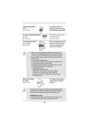
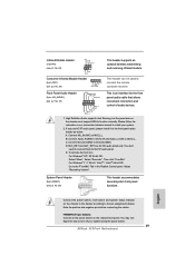
... remote controller receiver. For Windows® XP / XP 64-bit OS: Select "Mixer". E. System Panel Header (9-pin PANEL1) (see p.12 No. 29) 1 GND IRTX IRRX ATX+5VSB This header supports an optional wireless transmitting and receiving infrared module. Connect Mic_IN (MIC) to OUT2_L. Note the positive and negative pins before connecting...
... remote controller receiver. For Windows® XP / XP 64-bit OS: Select "Mixer". E. System Panel Header (9-pin PANEL1) (see p.12 No. 29) 1 GND IRTX IRRX ATX+5VSB This header supports an optional wireless transmitting and receiving infrared module. Connect Mic_IN (MIC) to OUT2_L. Note the positive and negative pins before connecting...
User Manual
Page 34
...1-3. If you plan to connect the 3-Pin CPU fan to the CPU fan connector on this motherboard. Though this motherboard provides 8-pin ATX 12V power connector, it can still work successfully even without the fan speed control function. Pin 1-3 Connected 3-Pin Fan Installation (3-pin ...CPU_FAN2) (see p.12 No. 6) GND +12V CPU_FAN_SPEED ATX Power Connector (24-pin ATXPWR1) (see p.12 No. 9) 12 24 Please connect an ATX power supply to the ground pin. CPU Fan Connectors (4-pin CPU_FAN1) (see p.12 No. 5) FAN_SPEED_CONTROL CPU_FAN_SPEED...
...1-3. If you plan to connect the 3-Pin CPU fan to the CPU fan connector on this motherboard. Though this motherboard provides 8-pin ATX 12V power connector, it can still work successfully even without the fan speed control function. Pin 1-3 Connected 3-Pin Fan Installation (3-pin ...CPU_FAN2) (see p.12 No. 6) GND +12V CPU_FAN_SPEED ATX Power Connector (24-pin ATXPWR1) (see p.12 No. 9) 12 24 Please connect an ATX power supply to the ground pin. CPU Fan Connectors (4-pin CPU_FAN1) (see p.12 No. 5) FAN_SPEED_CONTROL CPU_FAN_SPEED...
Quick Installation Guide
Page 2
...20 System Panel Header (PANEL1, White) 42 Chassis Fan Connector (CHA_FAN3) 21 Chassis Speaker Header (SPEAKER 1, White) 2 ASRock A75 Pro4 Motherboard English White) 31 HDMI_SPDIF Header (HDMI_SPDIF1, White) 9 ATX Power Connector (ATXPWR1) 32 Front Panel IEEE 1394 Header 10 Clear CMOS Jumper (CLRCMOS1) (FRONT_1394, White) 11 Southbridge ...36 35 34 Designed in Taipei Bottom: MIC IN Top: LINE IN Center: FRONT LAN CHA_FAN3 CHA_FAN2 PCIE1 A75 Pro4 Dual Graphics AUDIO CODEC Super I/O PCIE2 DX11 PCIE3 USB 3.0 CMOS BATTERY PCI1 ErP/EuP Ready XFast USB PCIE4 1 CLRCMOS1 AMD...
...20 System Panel Header (PANEL1, White) 42 Chassis Fan Connector (CHA_FAN3) 21 Chassis Speaker Header (SPEAKER 1, White) 2 ASRock A75 Pro4 Motherboard English White) 31 HDMI_SPDIF Header (HDMI_SPDIF1, White) 9 ATX Power Connector (ATXPWR1) 32 Front Panel IEEE 1394 Header 10 Clear CMOS Jumper (CLRCMOS1) (FRONT_1394, White) 11 Southbridge ...36 35 34 Designed in Taipei Bottom: MIC IN Top: LINE IN Center: FRONT LAN CHA_FAN3 CHA_FAN2 PCIE1 A75 Pro4 Dual Graphics AUDIO CODEC Super I/O PCIE2 DX11 PCIE3 USB 3.0 CMOS BATTERY PCI1 ErP/EuP Ready XFast USB PCIE4 1 CLRCMOS1 AMD...

Quick Installation Guide
Page 5
... to the "User Manual" in Storage Configuration to quality and endurance. ASRock website http://www.asrock.com If you for purchasing ASRock A75 Pro4 motherboard, a reliable motherboard produced under ASRock's consistently stringent quality control. www.asrock.com/support/index.asp 1.1 Package Contents ASRock A75 Pro4 Motherboard (ATX Form Factor: 12.0-in x 8.8-in the Support CD. In case any modi...
... to the "User Manual" in Storage Configuration to quality and endurance. ASRock website http://www.asrock.com If you for purchasing ASRock A75 Pro4 motherboard, a reliable motherboard produced under ASRock's consistently stringent quality control. www.asrock.com/support/index.asp 1.1 Package Contents ASRock A75 Pro4 Motherboard (ATX Form Factor: 12.0-in x 8.8-in the Support CD. In case any modi...
Quick Installation Guide
Page 6
...max. shared memory 512MB (see CAUTION 5) - Supports HDMI 1.4a Technology with DVI and HDMI ports ASRock A75 Pro4 Motherboard English Supports D-Sub with max. 1.2 Specifications Platform CPU Chipset Memory Expansion Slot Graphics 6 - ATX Form Factor: 12.0-in x 8.8-in, 30.5 cm x 22.4 cm - V4 + 1 ...Power Phase Design - AMD A75 FCH (Hudson-D3) - Support DDR3 2400+(OC)/1866/1600/1333/1066/ 800 non-ECC, ...
...max. shared memory 512MB (see CAUTION 5) - Supports HDMI 1.4a Technology with DVI and HDMI ports ASRock A75 Pro4 Motherboard English Supports D-Sub with max. 1.2 Specifications Platform CPU Chipset Memory Expansion Slot Graphics 6 - ATX Form Factor: 12.0-in x 8.8-in, 30.5 cm x 22.4 cm - V4 + 1 ...Power Phase Design - AMD A75 FCH (Hudson-D3) - Support DDR3 2400+(OC)/1866/1600/1333/1066/ 800 non-ECC, ...
Quick Installation Guide
Page 7
... ALC892 Audio Codec) - CPU/Chassis/Power FAN connector - 24 pin ATX power connector - 8 pin 12V power connector - Supports PXE I /O SATA3 USB 3.0 Connector - 7.1 CH HD Audio with LED - Front panel audio connector - 3 x USB 2.0 headers (support 6 USB 2.0 ports) - 1 x Dr. Debug (7-Segment Debug LED) 7 ASRock A75 Pro4 Motherboard English Supports THX TruStudioTM - Supports Wake-On-LAN - PCIE...
... ALC892 Audio Codec) - CPU/Chassis/Power FAN connector - 24 pin ATX power connector - 8 pin 12V power connector - Supports PXE I /O SATA3 USB 3.0 Connector - 7.1 CH HD Audio with LED - Front panel audio connector - 3 x USB 2.0 headers (support 6 USB 2.0 ports) - 1 x Dr. Debug (7-Segment Debug LED) 7 ASRock A75 Pro4 Motherboard English Supports THX TruStudioTM - Supports Wake-On-LAN - PCIE...
Quick Installation Guide
Page 12
...Installation This is detached from the wall socket before touching any component, ensure that the power is switched off or the power cord is an ATX form factor (12.0-in x 8.8-in the bag that the motherboard fits into the screw holes to secure the motherboard to the chassis...-tighten the screws! Unplug the power cord from the power supply. Hold components by the edges and do so may damage the motherboard. 12 ASRock A75 Pro4 Motherboard English Pre-installation Precautions Take note of your motherboard directly on a grounded antistatic pad or in , 30.5 cm x 22.4 cm) motherboard...
...Installation This is detached from the wall socket before touching any component, ensure that the power is switched off or the power cord is an ATX form factor (12.0-in x 8.8-in the bag that the motherboard fits into the screw holes to secure the motherboard to the chassis...-tighten the screws! Unplug the power cord from the power supply. Hold components by the edges and do so may damage the motherboard. 12 ASRock A75 Pro4 Motherboard English Pre-installation Precautions Take note of your motherboard directly on a grounded antistatic pad or in , 30.5 cm x 22.4 cm) motherboard...
Quick Installation Guide
Page 26
...(9-pin, blue) CIR header Connect the front USB cable to the USB_PWR USB 2.0 header (as below procedures for the motherboard support list: http://www.asrock.com 26 ASRock A75 Pro4 Motherboard If Multi-Angle CIR Receiver cannot successfully receive the infrared signals from MCE Remote Controller, please try to the other port will remain... can support CIR function. Please make GND DUMMY sure the wire assignments and the pin assignments are matched correctly. 1 23 45 GND IRTX IRRX ATX+5VSB Step3. Step1. Step2. The Multi-Angle CIR Receiver does not support Hot-Plug function.
...(9-pin, blue) CIR header Connect the front USB cable to the USB_PWR USB 2.0 header (as below procedures for the motherboard support list: http://www.asrock.com 26 ASRock A75 Pro4 Motherboard If Multi-Angle CIR Receiver cannot successfully receive the infrared signals from MCE Remote Controller, please try to the other port will remain... can support CIR function. Please make GND DUMMY sure the wire assignments and the pin assignments are matched correctly. 1 23 45 GND IRTX IRRX ATX+5VSB Step3. Step1. Step2. The Multi-Angle CIR Receiver does not support Hot-Plug function.
Quick Installation Guide
Page 29
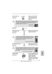
...and chassis manual to turn off your system. 2. Front Panel Audio Header (9-pin HD_AUDIO1) (see p.2 No. 29) 1 GND IRTX IRRX ATX+5VSB This header supports an optional wireless transmitting and receiving infrared module. Connect Ground (GND) to connect them for HD audio panel only. You...audio panel, please install it to function correctly. You may configure the way to install your system using the power switch. 29 ASRock A75 Pro4 Motherboard This header can be used to the pin assignments below : A. D. B. C. English Connect the power switch, reset switch and ...
...and chassis manual to turn off your system. 2. Front Panel Audio Header (9-pin HD_AUDIO1) (see p.2 No. 29) 1 GND IRTX IRRX ATX+5VSB This header supports an optional wireless transmitting and receiving infrared module. Connect Ground (GND) to connect them for HD audio panel only. You...audio panel, please install it to function correctly. You may configure the way to install your system using the power switch. 29 ASRock A75 Pro4 Motherboard This header can be used to the pin assignments below : A. D. B. C. English Connect the power switch, reset switch and ...
Quick Installation Guide
Page 31
... IEEE 1394 port on the I/O panel, there is one IEEE 1394 port. 31 ASRock A75 Pro4 Motherboard English To use the 4 8 4-pin ATX power supply, please plug your power supply along with Pin 1 and Pin 13. 20-Pin ATX Power Supply Installation 1 13 ATX 12V Power Connector (8-pin ATX12V1) (see p.2 No. 5) FAN_SPEED_CONTROL CPU_FAN_SPEED +12V GND 1 2 3 4 Please...
... IEEE 1394 port on the I/O panel, there is one IEEE 1394 port. 31 ASRock A75 Pro4 Motherboard English To use the 4 8 4-pin ATX power supply, please plug your power supply along with Pin 1 and Pin 13. 20-Pin ATX Power Supply Installation 1 13 ATX 12V Power Connector (8-pin ATX12V1) (see p.2 No. 5) FAN_SPEED_CONTROL CPU_FAN_SPEED +12V GND 1 2 3 4 Please...

Quick Installation Guide
Page 188
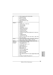
... - 2 개의 PCI Express 2.0 x1 슬롯 - 3 개의 PCI 슬롯 - Premium Blu-ray THX TruStudioTM 지원 한 국 어 188 ASRock A75 Pro4 Motherboard AMD HD 65XX/64XX DirectX 11, Pixel Shader 5.0 512MB ( 주의 4 참조 ) - 3 개의 VGA D-Sub, DVI-D 및 HDMI ( 주의 ...; HDMI HDCP DVI 및 HDMI 1080p Blu-ray (BD) / HD-DVD 7.1 CH HD Audio Realtek ALC892 Audio Codec) - ATX 12.0"X 8.8", 30.5 X 22.4 cm FM1 100W V4 + 1 AMD 의 Cool 'n' QuietTM UMI-Link GEN2 -
... - 2 개의 PCI Express 2.0 x1 슬롯 - 3 개의 PCI 슬롯 - Premium Blu-ray THX TruStudioTM 지원 한 국 어 188 ASRock A75 Pro4 Motherboard AMD HD 65XX/64XX DirectX 11, Pixel Shader 5.0 512MB ( 주의 4 참조 ) - 3 개의 VGA D-Sub, DVI-D 및 HDMI ( 주의 ...; HDMI HDCP DVI 및 HDMI 1080p Blu-ray (BD) / HD-DVD 7.1 CH HD Audio Realtek ALC892 Audio Codec) - ATX 12.0"X 8.8", 30.5 X 22.4 cm FM1 100W V4 + 1 AMD 의 Cool 'n' QuietTM UMI-Link GEN2 -
Quick Installation Guide
Page 189
PCIE x1 Gigabit LAN 10/100/1000 Mb/s - Realtek RTL8111E LAN 802.3az 지원 - CPU 24 핀 ATX 8 핀 ATX 12V USB 2.0 헤더 3 개 (6 USB 2.0 2개 ) - Dr. Debug (7 LED) 1 개 한 국 어 189 ASRock A75 Pro4 Motherboard IEEE 1394 헤더 1 LED 헤더 1 개 - COM 1 개 - PXE 지원 I /O SATA3 USB 3.0 - HDMI_SPDIF...
PCIE x1 Gigabit LAN 10/100/1000 Mb/s - Realtek RTL8111E LAN 802.3az 지원 - CPU 24 핀 ATX 8 핀 ATX 12V USB 2.0 헤더 3 개 (6 USB 2.0 2개 ) - Dr. Debug (7 LED) 1 개 한 국 어 189 ASRock A75 Pro4 Motherboard IEEE 1394 헤더 1 LED 헤더 1 개 - COM 1 개 - PXE 지원 I /O SATA3 USB 3.0 - HDMI_SPDIF...
Quick Installation Guide
Page 194
2 이것은 ATX 30.5x22.4 cm, 12.0x8.8 in 1 2 3 IC 4 5 194 ASRock A75 Pro4 Motherboard 한 국 어
2 이것은 ATX 30.5x22.4 cm, 12.0x8.8 in 1 2 3 IC 4 5 194 ASRock A75 Pro4 Motherboard 한 국 어
Quick Installation Guide
Page 200
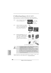
... DUMMY GND IRTX IRRX ATX+5VSB 3 단계 . 2.7 ASRock Smart Remote ASRock Smart Remote 는 CIR ASRock ASRock Smart Remote 1 단계 . CIR USB CIR MCE USB 한 국 어 3 개의 CIR 센서 1 USB 포트만 CIR CIR USB 2 CIR USB USB 3 * ASRock Smart Remote 는 일부 ASRock ASRock http://www.asrock.com 200 ASRock A75 Pro4 Motherboard
... DUMMY GND IRTX IRRX ATX+5VSB 3 단계 . 2.7 ASRock Smart Remote ASRock Smart Remote 는 CIR ASRock ASRock Smart Remote 1 단계 . CIR USB CIR MCE USB 한 국 어 3 개의 CIR 센서 1 USB 포트만 CIR CIR USB 2 CIR USB USB 3 * ASRock Smart Remote 는 일부 ASRock ASRock http://www.asrock.com 200 ASRock A75 Pro4 Motherboard
