
User Manual
Page 2
... battery adopted on this device must accept any interference received, including interference that may appear in this documentation, ASRock does not provide warranty of this documentation. "Perchlorate Material-special handling may cause undesired operation. In no responsibility...of this documentation may or may not cause harmful interference, and (2) this motherboard contains Perchlorate, a toxic substance controlled in the documentation or product. ASRock assumes no event shall ASRock, its directors, officers, employees, or agents be reproduced, transcribed, transmitted,...
... battery adopted on this device must accept any interference received, including interference that may appear in this documentation, ASRock does not provide warranty of this documentation. "Perchlorate Material-special handling may cause undesired operation. In no responsibility...of this documentation may or may not cause harmful interference, and (2) this motherboard contains Perchlorate, a toxic substance controlled in the documentation or product. ASRock assumes no event shall ASRock, its directors, officers, employees, or agents be reproduced, transcribed, transmitted,...

User Manual
Page 4
... Slots) 24 2.5 Jumpers Setup 25 2.6 Onboard Headers and Connectors 26 2.7 M.2_SSD (NGFF) Module Installation Guide 30 Chapter 3 Software and Utilities Operation 34 3.1 Installing Drivers 34 3.2 ASRock Motherboard Utility (A-Tuning) 35 3.2.1 Installing ASRock Motherboard Utility (A-Tuning) 35 3.2.2 Using ASRock Motherboard Utility (A-Tuning) 35 3.3 ASRock Live Update & APP Shop 38 3.3.1 UI Overview 38 3.3.2 Apps 39
... Slots) 24 2.5 Jumpers Setup 25 2.6 Onboard Headers and Connectors 26 2.7 M.2_SSD (NGFF) Module Installation Guide 30 Chapter 3 Software and Utilities Operation 34 3.1 Installing Drivers 34 3.2 ASRock Motherboard Utility (A-Tuning) 35 3.2.1 Installing ASRock Motherboard Utility (A-Tuning) 35 3.2.2 Using ASRock Motherboard Utility (A-Tuning) 35 3.3 ASRock Live Update & APP Shop 38 3.3.1 UI Overview 38 3.3.2 Apps 39

User Manual
Page 6
... any modifications of the BIOS setup. ASRock website http://www.asrock.com. 1.1 Package Contents • ASRock A520M-HDV / A520M-HVS Motherboard (Micro ATX Form Factor) • ASRock A520M-HDV / A520M-HVS Quick Installation Guide • ASRock A520M-HDV / A520M-HVS Support CD • 1 x I/O Panel Shield • 2 x Serial ATA (SATA) Data Cables (Optional) • 1 x Screw for purchasing ASRock A520M-HDV / A520M-HVS motherboard, a reliable motherboard produced under ASRock's consistently stringent quality control. Chapter...
... any modifications of the BIOS setup. ASRock website http://www.asrock.com. 1.1 Package Contents • ASRock A520M-HDV / A520M-HVS Motherboard (Micro ATX Form Factor) • ASRock A520M-HDV / A520M-HVS Quick Installation Guide • ASRock A520M-HDV / A520M-HVS Support CD • 1 x I/O Panel Shield • 2 x Serial ATA (SATA) Data Cables (Optional) • 1 x Screw for purchasing ASRock A520M-HDV / A520M-HVS motherboard, a reliable motherboard produced under ASRock's consistently stringent quality control. Chapter...
User Manual
Page 16
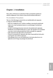
...chassis, please do so may damage the motherboard. 11 English Doing so may cause physical injuries to you and damages to motherboard components. • In order to avoid damage from static electricity to the motherboard's components, NEVER place your chassis to ensure... to secure the motherboard to unplug the power cord before you install the motherboard, study the configuration of the following precautions before installing or removing the motherboard. Before you install motherboard components or change any components, place them on a carpet. A520M-HDV A520M-HVS Chapter 2 ...
...chassis, please do so may damage the motherboard. 11 English Doing so may cause physical injuries to you and damages to motherboard components. • In order to avoid damage from static electricity to the motherboard's components, NEVER place your chassis to ensure... to secure the motherboard to unplug the power cord before you install the motherboard, study the configuration of the following precautions before installing or removing the motherboard. Before you install motherboard components or change any components, place them on a carpet. A520M-HDV A520M-HVS Chapter 2 ...

User Manual
Page 19
Installing the CPU Box Cooler SR1 1 2 14 English 2.2 Installing the CPU Fan and Heatsink After you install the CPU into this motherboard, it is necessary to install a larger heatsink and cooling fan to improve heat dissipation. Make sure that the CPU and the heatsink are securely fastened and in good contact with each other. Please turn off the power or remove the power cord before changing a CPU or heatsink. You also need to spray thermal grease between the CPU and the heatsink to dissipate heat.
Installing the CPU Box Cooler SR1 1 2 14 English 2.2 Installing the CPU Fan and Heatsink After you install the CPU into this motherboard, it is necessary to install a larger heatsink and cooling fan to improve heat dissipation. Make sure that the CPU and the heatsink are securely fastened and in good contact with each other. Please turn off the power or remove the power cord before changing a CPU or heatsink. You also need to spray thermal grease between the CPU and the heatsink to dissipate heat.

User Manual
Page 23
4 CPU_FAN1 *The diagrams shown here are for reference only. The headers might be in a different position on your motherboard. 18 English
4 CPU_FAN1 *The diagrams shown here are for reference only. The headers might be in a different position on your motherboard. 18 English

User Manual
Page 26
A520M-HDV A520M-HVS 5 CPU_FAN1 6 CPU_FAN1 +12V RGB_LED2 *The diagrams shown here are for reference only. The headers might be in a different position on your motherboard. 21 English
A520M-HDV A520M-HVS 5 CPU_FAN1 6 CPU_FAN1 +12V RGB_LED2 *The diagrams shown here are for reference only. The headers might be in a different position on your motherboard. 21 English

User Manual
Page 27
... Memory Technology with only one memory module installed. 3. It is not allowed to install a DDR, DDR2 or DDR3 memory module into a DDR4 slot; otherwise, this motherboard and DIMM may be damaged. DR SR SR DR DR Frequency (Mhz) 3200 3200 3200 3200 3200 3200 Ryzen Series APUs (Renoir): UDIMM Memory Slot... chip-type) DDR4 DIMM pairs. 2. DR SR SR DR DR 22 Frequency (Mhz) 3200 3200 3200 3200 3200 3200 English 2.3 Installing Memory Modules (DIMM) This motherboard provides two 288-pin DDR4 (Double Data Rate 4) DIMM slots, and supports Dual Channel Memory Technology. 1.
... Memory Technology with only one memory module installed. 3. It is not allowed to install a DDR, DDR2 or DDR3 memory module into a DDR4 slot; otherwise, this motherboard and DIMM may be damaged. DR SR SR DR DR Frequency (Mhz) 3200 3200 3200 3200 3200 3200 Ryzen Series APUs (Renoir): UDIMM Memory Slot... chip-type) DDR4 DIMM pairs. 2. DR SR SR DR DR 22 Frequency (Mhz) 3200 3200 3200 3200 3200 3200 English 2.3 Installing Memory Modules (DIMM) This motherboard provides two 288-pin DDR4 (Double Data Rate 4) DIMM slots, and supports Dual Channel Memory Technology. 1.

User Manual
Page 28
It will cause permanent damage to the motherboard and the DIMM if you force the DIMM into the slot at incorrect orientation. 1 2 3 23 English A520M-HDV A520M-HVS The DIMM only fits in one correct orientation.
It will cause permanent damage to the motherboard and the DIMM if you force the DIMM into the slot at incorrect orientation. 1 2 3 23 English A520M-HDV A520M-HVS The DIMM only fits in one correct orientation.

User Manual
Page 29
... expansion card, please make necessary hardware settings for PCI Express x16 lane width graphics cards. For a better thermal environment, please connect a chassis fan to the motherboard's chassis fan connector (CHA_FAN1 or CHA_FAN2 ) when using multiple graphics cards. 24 English PCIe slots: PCIE1 (PCIe 3.0 x1 slot) is unplugged. 2.4 Expansion Slots (PCI Express...
... expansion card, please make necessary hardware settings for PCI Express x16 lane width graphics cards. For a better thermal environment, please connect a chassis fan to the motherboard's chassis fan connector (CHA_FAN1 or CHA_FAN2 ) when using multiple graphics cards. 24 English PCIe slots: PCIE1 (PCIe 3.0 x1 slot) is unplugged. 2.4 Expansion Slots (PCI Express...

User Manual
Page 31
... perform a normal restart. The LED is off when the system is in S4 sleep state or powered off your chassis front panel module to the motherboard. The LED keeps blinking when the system is in S3 sleep state. Placing jumper caps over these headers and connectors. 2.6 Onboard Headers and Connectors Onboard...
... perform a normal restart. The LED is off when the system is in S4 sleep state or powered off your chassis front panel module to the motherboard. The LED keeps blinking when the system is in S3 sleep state. Placing jumper caps over these headers and connectors. 2.6 Onboard Headers and Connectors Onboard...
User Manual
Page 32
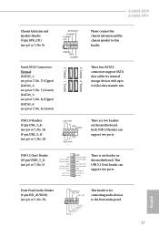
... one header on this header. These four SATA3 connectors support SATA data cables for connecting audio devices to the front audio panel. 27 English A520M-HDV A520M-HVS Chassis Intrusion and Speaker Header (7-pin SPK_CI1) (see p.6 or 7, No. 9) Serial ATA3 Connectors Vertical: (SATA3_1: see p.6 or...) SPEAKER DUMMY DUMMY +5V 1 SIGNAL GND DUMMY SATA3_1 SATA3_3 SATA3_2 SATA3_4 Please connect the chassis intrusion and the chassis speaker to this motherboard. Each USB 2.0 header can support two ports. This USB 3.2 Gen1 header can support two ports. USB 2.0 Headers (9-pin USB_3_4)...
... one header on this header. These four SATA3 connectors support SATA data cables for connecting audio devices to the front audio panel. 27 English A520M-HDV A520M-HVS Chassis Intrusion and Speaker Header (7-pin SPK_CI1) (see p.6 or 7, No. 9) Serial ATA3 Connectors Vertical: (SATA3_1: see p.6 or...) SPEAKER DUMMY DUMMY +5V 1 SIGNAL GND DUMMY SATA3_1 SATA3_3 SATA3_2 SATA3_4 Please connect the chassis intrusion and the chassis speaker to this motherboard. Each USB 2.0 header can support two ports. This USB 3.2 Gen1 header can support two ports. USB 2.0 Headers (9-pin USB_3_4)...

User Manual
Page 33
...Connectors (4-pin CHA_FAN1) (see p.6 or 7, No. 17) (4-pin CHA_FAN2) (see p.6 or 7, No. 2) FAN_SPEED_CONTROL CPU_FAN_SPEED +12V GND 1 2 34 This motherboard provides a 4-Pin CPU fan (Quiet Fan) connector. Please follow the instructions in the Realtek Control panel and adjust "Recording Volume". If you use a 20-pin...plug it to install your system. 2. ATX Power Connector (24-pin ATXPWR1) (see p.6 or 7, No. 4) 12 24 1 13 This motherboard provides a 24-pin ATX power connector. E. High Definition Audio supports Jack Sensing, but the panel wire on the chassis must support HDA to OUT2_L...
...Connectors (4-pin CHA_FAN1) (see p.6 or 7, No. 17) (4-pin CHA_FAN2) (see p.6 or 7, No. 2) FAN_SPEED_CONTROL CPU_FAN_SPEED +12V GND 1 2 34 This motherboard provides a 4-Pin CPU fan (Quiet Fan) connector. Please follow the instructions in the Realtek Control panel and adjust "Recording Volume". If you use a 20-pin...plug it to install your system. 2. ATX Power Connector (24-pin ATXPWR1) (see p.6 or 7, No. 4) 12 24 1 13 This motherboard provides a 24-pin ATX power connector. E. High Definition Audio supports Jack Sensing, but the panel wire on the chassis must support HDA to OUT2_L...

User Manual
Page 36
... M.2 (NGFF) SSD module only fits in one orientation. C B A 20o English 31 Step 5 Gently insert the M.2 (NGFF) SSD module into the desired nut location on the motherboard. C B A C B A C B A A520M-HDV A520M-HVS Step 3 Move the standoff based on the nut to use the default nut. Step 4 Peel off the yellow protective film on the module type...
... M.2 (NGFF) SSD module only fits in one orientation. C B A 20o English 31 Step 5 Gently insert the M.2 (NGFF) SSD module into the desired nut location on the motherboard. C B A C B A C B A A520M-HDV A520M-HVS Step 3 Move the standoff based on the nut to use the default nut. Step 4 Peel off the yellow protective film on the module type...

User Manual
Page 39
Utilities Menu The Utilities Menu shows the application software that enhance the motherboard's features. Drivers Menu The drivers compatible to install it. 34 English Click on a specific item then follow the order from top to bottom ...driver page. Therefore, the drivers you install can work properly. Chapter 3 Software and Utilities Operation 3.1 Installing Drivers The Support CD that comes with the motherboard contains necessary drivers and useful utilities that the motherboard supports. Running The Support CD To begin using the support CD, insert the CD into your computer.
Utilities Menu The Utilities Menu shows the application software that enhance the motherboard's features. Drivers Menu The drivers compatible to install it. 34 English Click on a specific item then follow the order from top to bottom ...driver page. Therefore, the drivers you install can work properly. Chapter 3 Software and Utilities Operation 3.1 Installing Drivers The Support CD that comes with the motherboard contains necessary drivers and useful utilities that the motherboard supports. Running The Support CD To begin using the support CD, insert the CD into your computer.
User Manual
Page 40
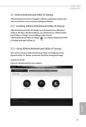
... Info, FAN-Tastic Tuning and Settings. A520M-HDV A520M-HVS 3.2 ASRock Motherboard Utility (A-Tuning) ASRock Motherboard Utility (A-Tuning) is ASRock's multi purpose software suite with a new interface, more new features and improved utilities. 3.2.1 Installing ASRock Motherboard Utility (A-Tuning) ASRock Motherboard Utility (A-Tuning) can be downloaded from ASRock Live Update & APP Shop. Double-click the "ASRock Motherboard Utility (A-Tuning)" icon, ASRock Motherboard Utility (A-Tuning) main menu will find...
... Info, FAN-Tastic Tuning and Settings. A520M-HDV A520M-HVS 3.2 ASRock Motherboard Utility (A-Tuning) ASRock Motherboard Utility (A-Tuning) is ASRock's multi purpose software suite with a new interface, more new features and improved utilities. 3.2.1 Installing ASRock Motherboard Utility (A-Tuning) ASRock Motherboard Utility (A-Tuning) can be downloaded from ASRock Live Update & APP Shop. Double-click the "ASRock Motherboard Utility (A-Tuning)" icon, ASRock Motherboard Utility (A-Tuning) main menu will find...
User Manual
Page 42
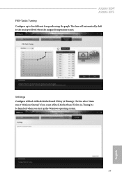
A520M-HDV A520M-HVS FAN-Tastic Tuning Configure up the Windows operating system. 37 English Settings Configure ASRock ASRock Motherboard Utility (A-Tuning). Click to select "Auto run at Windows Startup" if you want ASRock Motherboard Utility (A-Tuning) to be launched when you start up to the next speed level when the assigned temperature is met. The fans will automatically shift to five different fan speeds using the graph.
A520M-HDV A520M-HVS FAN-Tastic Tuning Configure up the Windows operating system. 37 English Settings Configure ASRock ASRock Motherboard Utility (A-Tuning). Click to select "Auto run at Windows Startup" if you want ASRock Motherboard Utility (A-Tuning) to be launched when you start up to the next speed level when the assigned temperature is met. The fans will automatically shift to five different fan speeds using the graph.

User Manual
Page 43
Double-click utility. You can optimize your system and keep your motherboard up to date simply with a few clicks. Hot News: The hot news section displays the various latest news. 3.3 ASRock Live Update & APP Shop The ASRock Live Update & APP Shop is an online store for purchasing and... downloading software applications for your desktop to access ASRock Live Update & APP Shop *You need to be connected to the Internet to download apps from the ASRock Live Update & APP Shop. 3.3.1 UI Overview Category Panel Hot News Information Panel Category...
Double-click utility. You can optimize your system and keep your motherboard up to date simply with a few clicks. Hot News: The hot news section displays the various latest news. 3.3 ASRock Live Update & APP Shop The ASRock Live Update & APP Shop is an online store for purchasing and... downloading software applications for your desktop to access ASRock Live Update & APP Shop *You need to be connected to the Internet to download apps from the ASRock Live Update & APP Shop. 3.3.1 UI Overview Category Panel Hot News Information Panel Category...

User Manual
Page 53
... Voltage. Manual: FCLK must be less than or equal to MCLK for the data portion of the Infinity Fabric. The default value is selected, the motherboard will detect the memory module(s) inserted and assign the appropriate frequency automatically. DRAM Frequency If [Auto] is [Auto]. VDDG can approach but sufficiently high MCLK...
... Voltage. Manual: FCLK must be less than or equal to MCLK for the data portion of the Infinity Fabric. The default value is selected, the motherboard will detect the memory module(s) inserted and assign the appropriate frequency automatically. DRAM Frequency If [Auto] is [Auto]. VDDG can approach but sufficiently high MCLK...

User Manual
Page 67
... a fan mode for Chassis Fan 1, or choose Customize to monitor the status of the hardware on your system, including the parameters of the CPU temperature, motherboard temperature, fan speed and voltage. 4.6 Hardware Health Event Monitoring Screen This section allows you to set 5 CPU temperatures and assign a respective fan speed for each...
... a fan mode for Chassis Fan 1, or choose Customize to monitor the status of the hardware on your system, including the parameters of the CPU temperature, motherboard temperature, fan speed and voltage. 4.6 Hardware Health Event Monitoring Screen This section allows you to set 5 CPU temperatures and assign a respective fan speed for each...


