
User Manual
Page 3
... Setup Guide 19 2.9 Serial ATA (SATA) / Serial ATAII (SATAII) Hard Disks Installation 20 2.10 Driver Installation Guide 20 2.11 Untied Overclocking Technology 20 3 BIOS SETUP UTILITY 21 3.1 Introduction 21 3.1.1 BIOS Menu Bar 21 3.1.2 Navigation Keys 22 3.2 Main Screen 22 3.3 Smart Screen 23 3.4 Advanced Screen 25 3.4.1 CPU Configuration 25 3.4.2 Chipset Configuration 26 3.4.3 ACPI...
... Setup Guide 19 2.9 Serial ATA (SATA) / Serial ATAII (SATAII) Hard Disks Installation 20 2.10 Driver Installation Guide 20 2.11 Untied Overclocking Technology 20 3 BIOS SETUP UTILITY 21 3.1 Introduction 21 3.1.1 BIOS Menu Bar 21 3.1.2 Navigation Keys 22 3.2 Main Screen 22 3.3 Smart Screen 23 3.4 Advanced Screen 25 3.4.1 CPU Configuration 25 3.4.2 Chipset Configuration 26 3.4.3 ACPI...
User Manual
Page 5
... you are using. Because the motherboard specifications and the BIOS software might be updated, the content of the motherboard and step-by-step guide to change without further notice. www.asrock.com/support/index.asp 1.1 Package Contents ASRock A330GC / A230GC Motherboard (Mini-ITX Form Factor: 6.7-in ..., 17.0 cm x 17.0 cm) One Bundled Intel® Dual-Core AtomTM Processor 330 (A330GC) One Bundled Intel® AtomTM Processor 230 (A230GC) ASRock A330GC / A230GC Quick Installation Guide ASRock A330GC / A230GC Support CD One 80-conductor Ultra ATA 66/100 IDE Ribbon Cable One Serial ATA...
... you are using. Because the motherboard specifications and the BIOS software might be updated, the content of the motherboard and step-by-step guide to change without further notice. www.asrock.com/support/index.asp 1.1 Package Contents ASRock A330GC / A230GC Motherboard (Mini-ITX Form Factor: 6.7-in ..., 17.0 cm x 17.0 cm) One Bundled Intel® Dual-Core AtomTM Processor 330 (A330GC) One Bundled Intel® AtomTM Processor 230 (A230GC) ASRock A330GC / A230GC Quick Installation Guide ASRock A330GC / A230GC Support CD One 80-conductor Ultra ATA 66/100 IDE Ribbon Cable One Serial ATA...

User Manual
Page 7
...- Hybrid Booster: - Chassis Fan Tachometer - We are not responsible for possible damage caused by overclocking. 7 AMI Legal BIOS - AMBIOS 2.3.1 Support - ASRock U-COP (see CAUTION 8) - Boot Failure Guard (B.F.G.) Hardware - Microsoft® Windows® 2000 / XP / XP... - ACPI 1.1 Compliance Wake Up Events - Supports Smart BIOS Support CD - Drivers, Utilities, AntiVirus Software (Trial Version) Unique Feature - Instant Boot - ASRock Instant Flash (see CAUTION 7) BIOS Feature - 4Mb AMI BIOS - CPU Frequency Stepless Control (see CAUTION 10) - Chassis...
...- Hybrid Booster: - Chassis Fan Tachometer - We are not responsible for possible damage caused by overclocking. 7 AMI Legal BIOS - AMBIOS 2.3.1 Support - ASRock U-COP (see CAUTION 8) - Boot Failure Guard (B.F.G.) Hardware - Microsoft® Windows® 2000 / XP / XP... - ACPI 1.1 Compliance Wake Up Events - Supports Smart BIOS Support CD - Drivers, Utilities, AntiVirus Software (Trial Version) Unique Feature - Instant Boot - ASRock Instant Flash (see CAUTION 7) BIOS Feature - 4Mb AMI BIOS - CPU Frequency Stepless Control (see CAUTION 10) - Chassis...
User Manual
Page 8
...get the best system performance under Windows® environment. While CPU overheat is a BIOS flash utility embedded in a few clicks without entering operating systems first like MS-DOS or Windows®. About the setting of ASRock OC Tuner. Please check Intel® website for details. 3. You can press... key during the POST or press key to BIOS setup menu to change. Just launch this tool and save the new...
...get the best system performance under Windows® environment. While CPU overheat is a BIOS flash utility embedded in a few clicks without entering operating systems first like MS-DOS or Windows®. About the setting of ASRock OC Tuner. Please check Intel® website for details. 3. You can press... key during the POST or press key to BIOS setup menu to change. Just launch this tool and save the new...

User Manual
Page 9
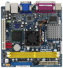
...) 18 South Bridge Controller 8 IDE1 Connector (IDE1, Blue) 19 PS2_USB_PWR1 Jumper 9 System Panel Header (PANEL1, Orange) 20 USB 2.0 Header (USB6_7, Blue) 10 BIOS SPI Chip 21 USB 2.0 Header (USB4_5, Blue) 11 Chassis Speaker Header (SPEAKER 1, Purple) 9 1.3 Motherboard Layout PS2 Keyboard 1 2 3 45 6 17.0cm... LAN T: USB0 B: USB1 Top: RJ-45 PHY 1 PS2_USB_PWR1 1 USB6_7 1 USB4_5 Intel ICH7 CMOS Battery 18 PANEL 1 9 CD1 4Mb BIOS SATAII_1 SATAII_2 PLED PWRBTN 1 HDLED RESET 1 HD_AUDIO1 Top: Line In Center: Line Out Bottom: Mic In AUDIO CODEC PCI1 CLRCMOS1 SPEAKER1 1...
...) 18 South Bridge Controller 8 IDE1 Connector (IDE1, Blue) 19 PS2_USB_PWR1 Jumper 9 System Panel Header (PANEL1, Orange) 20 USB 2.0 Header (USB6_7, Blue) 10 BIOS SPI Chip 21 USB 2.0 Header (USB4_5, Blue) 11 Chassis Speaker Header (SPEAKER 1, Purple) 9 1.3 Motherboard Layout PS2 Keyboard 1 2 3 45 6 17.0cm... LAN T: USB0 B: USB1 Top: RJ-45 PHY 1 PS2_USB_PWR1 1 USB6_7 1 USB4_5 Intel ICH7 CMOS Battery 18 PANEL 1 9 CD1 4Mb BIOS SATAII_1 SATAII_2 PLED PWRBTN 1 HDLED RESET 1 HD_AUDIO1 Top: Line In Center: Line Out Bottom: Mic In AUDIO CODEC PCI1 CLRCMOS1 SPEAKER1 1...

User Manual
Page 17
..." of audio devices. 1. E. Set the Front Panel Control option from sound sources such as the default record device. 17 G. Connect Ground (GND) to OUT2_L. Enter BIOS Setup Utility. F. Click "Set Default Device" to make the Front Mic as a CD-ROM, DVD-ROM, TV tuner card, or MPEG card. Internal Audio Connector...
..." of audio devices. 1. E. Set the Front Panel Control option from sound sources such as the default record device. 17 G. Connect Ground (GND) to OUT2_L. Enter BIOS Setup Utility. F. Click "Set Default Device" to make the Front Mic as a CD-ROM, DVD-ROM, TV tuner card, or MPEG card. Internal Audio Connector...

User Manual
Page 20
... fixed mode so that supports Serial ATA (SATA) / Serial ATAII (SATAII) hard disks. STEP 1: Install the SATA / SATAII hard disks into the drive bays of BIOS setup to set the selection from up to bottom side to the SATA / SATAII hard disk. 2.9 Serial ATA (SATA) / Serial ATAII (SATAII) Hard Disks Installation...
... fixed mode so that supports Serial ATA (SATA) / Serial ATAII (SATAII) hard disks. STEP 1: Install the SATA / SATAII hard disks into the drive bays of BIOS setup to set the selection from up to bottom side to the SATA / SATAII hard disk. 2.9 Serial ATA (SATA) / Serial ATAII (SATAII) Hard Disks Installation...

User Manual
Page 21
...< > key to choose among the selections on your requirements Advanced To set up the advanced BIOS features PCIPnP To set up the PCI features Boot To set up the default system device to... Chipset To set up the system time/date information Smart To load the BIOS according to your screen. 3.1.1 BIOS Menu Bar The top of the screen has a menu bar with its test routines. You... may run the BIOS SETUP UTILITY when you see on the menu bar, and then press to enter the BIOS SETUP UTILITY, otherwise, POST will continue with the following selections: ...
...< > key to choose among the selections on your requirements Advanced To set up the advanced BIOS features PCIPnP To set up the PCI features Boot To set up the default system device to... Chipset To set up the system time/date information Smart To load the BIOS according to your screen. 3.1.1 BIOS Menu Bar The top of the screen has a menu bar with its test routines. You... may run the BIOS SETUP UTILITY when you see on the menu bar, and then press to enter the BIOS SETUP UTILITY, otherwise, POST will continue with the following selections: ...
User Manual
Page 22
...To jump to the Exit Screen or exit the current screen 3.2 Main Screen When you enter the BIOS SETUP UTILITY, the Main screen will appear and display the system overview. A330GC BIOS SETUP UTILITY Main Smart Advanced H/W Monitor Boot Security Exit System Overview System Time System Date [14:...00:09] [Wed 05/13/2009] BIOS Version : A330GC P1.00 Processor Type : Intel (R) Atom (TM) CPU 330 @ 1.60GHz (64bit) Processor Speed : 1600MHz Microcode Update : 106C2/213 Cache Size : ...
...To jump to the Exit Screen or exit the current screen 3.2 Main Screen When you enter the BIOS SETUP UTILITY, the Main screen will appear and display the system overview. A330GC BIOS SETUP UTILITY Main Smart Advanced H/W Monitor Boot Security Exit System Overview System Time System Date [14:...00:09] [Wed 05/13/2009] BIOS Version : A330GC P1.00 Processor Type : Intel (R) Atom (TM) CPU 330 @ 1.60GHz (64bit) Processor Speed : 1600MHz Microcode Update : 106C2/213 Cache Size : ...

User Manual
Page 23
... Load Performance Setup Default Load Power Saving Setup Default EZ Overclocking Load Optimized CPU OC Setting [Press Enter] BIOS Update Utility ASRock Instant Flash Exit system setup after saving the changes. Use [+] or [-] to Sub Screen F1 General Help F9 Load Defaults F10 Save and Exit ...ESC Exit v02.54 (C) Copyright 1985-2005, American Megatrends, Inc. F10 key can load the BIOS setup according to specify the system date. 3.3 Smart ...
... Load Performance Setup Default Load Power Saving Setup Default EZ Overclocking Load Optimized CPU OC Setting [Press Enter] BIOS Update Utility ASRock Instant Flash Exit system setup after saving the changes. Use [+] or [-] to Sub Screen F1 General Help F9 Load Defaults F10 Save and Exit ...ESC Exit v02.54 (C) Copyright 1985-2005, American Megatrends, Inc. F10 key can load the BIOS setup according to specify the system date. 3.3 Smart ...

User Manual
Page 24
...USB flash drive, floppy disk or hard drive, then you execute ASRock Instant Flash utility, the utility will show the BIOS files and their respective information. Just launch this operation. Select the proper BIOS file to update your BIOS, and reboot your own risk and expense. Configuration options: [1.7 GHz... Default Load power saving setup default. Load Optimized CPU OC Setting You can update your CPU and motherboard. ASRock Instant Flash ASRock Instant Flash is a BIOS flash utility embedded in a few clicks without entering operating systems first like MS-DOS or Windows®. Please...
...USB flash drive, floppy disk or hard drive, then you execute ASRock Instant Flash utility, the utility will show the BIOS files and their respective information. Just launch this operation. Select the proper BIOS file to update your BIOS, and reboot your own risk and expense. Configuration options: [1.7 GHz... Default Load power saving setup default. Load Optimized CPU OC Setting You can update your CPU and motherboard. ASRock Instant Flash ASRock Instant Flash is a BIOS flash utility embedded in a few clicks without entering operating systems first like MS-DOS or Windows®. Please...

User Manual
Page 25
...Configuration, SuperIO Configuration, and USB Configuration. Setting wrong values in this section may cause the system to malfunction. 3.4.1 CPU Configuration BIOS SETUP UTILITY Advanced CPU Configuration WARNING : Setting wrong values in below sections may cause system to Sub Screen F1 General Help F9 ..., Inc. Overclock Mode Use this to adjust PCIE frequency. 25 PCIE Frequency (MHz) Use this option to select Overclock Mode. BIOS SETUP UTILITY Main Smart Advanced H/W Monitor Boot Security Exit Advanced Settings WARNING : Setting wrong values in below sections may set the ...
...Configuration, SuperIO Configuration, and USB Configuration. Setting wrong values in this section may cause the system to malfunction. 3.4.1 CPU Configuration BIOS SETUP UTILITY Advanced CPU Configuration WARNING : Setting wrong values in below sections may cause system to Sub Screen F1 General Help F9 ..., Inc. Overclock Mode Use this to adjust PCIE frequency. 25 PCIE Frequency (MHz) Use this option to select Overclock Mode. BIOS SETUP UTILITY Main Smart Advanced H/W Monitor Boot Security Exit Advanced Settings WARNING : Setting wrong values in below sections may set the ...
User Manual
Page 26
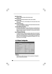
... CPU from being used by malicious software to [Enabled] if using Microsoft® Windows® XP, or Linux kernel version 2.4.18 or higher. 3.4.2 Chipset Configuration BIOS SETUP UTILITY Advanced Chipset Configuration DRAM tCL DRAM tRCD DRAM tRP DRAM tRAS Advanced DRAM Configuration Primary Graphics Adapter Internal Graphics Mode Select DVMT Mode...
... CPU from being used by malicious software to [Enabled] if using Microsoft® Windows® XP, or Linux kernel version 2.4.18 or higher. 3.4.2 Chipset Configuration BIOS SETUP UTILITY Advanced Chipset Configuration DRAM tCL DRAM tRCD DRAM tRP DRAM tRAS Advanced DRAM Configuration Primary Graphics Adapter Internal Graphics Mode Select DVMT Mode...

User Manual
Page 29
... system from the power-soft-off mode. If [Power Off] is [Disabled]. Please set the power state after an unexpected AC/Power loss. 3.4.3 ACPI Configuration BIOS SETUP UTILITY Advanced ACPI Configuration Suspend To RAM Restore on the system from the power-soft-off mode. Suspend to RAM This field allows you...
... system from the power-soft-off mode. If [Power Off] is [Disabled]. Please set the power state after an unexpected AC/Power loss. 3.4.3 ACPI Configuration BIOS SETUP UTILITY Advanced ACPI Configuration Suspend To RAM Restore on the system from the power-soft-off mode. Suspend to RAM This field allows you...

User Manual
Page 30
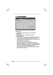
BIOS SETUP UTILITY Advanced Primary IDE Master Device Vendor Size LBA Mode Block Mode PIO Mode Async DMA Ultra DMA S.M.A.R.T. TYPE Use this item to automatically ... Master" as the example in the following instruction. IDE Device Configuration You may set the IDE configuration for the device that you specify. 3.4.4 IDE Configuration BIOS SETUP UTILITY Advanced IDE Configuration ATA/IDE Configuration SATAII_1 SATAII_2 IDE1 Master IDE1 Slave [Enhanced] [Not Detected] [Not Detected] [Not Detected] [Not Detected] Set [Compatible...
BIOS SETUP UTILITY Advanced Primary IDE Master Device Vendor Size LBA Mode Block Mode PIO Mode Async DMA Ultra DMA S.M.A.R.T. TYPE Use this item to automatically ... Master" as the example in the following instruction. IDE Device Configuration You may set the IDE configuration for the device that you specify. 3.4.4 IDE Configuration BIOS SETUP UTILITY Advanced IDE Configuration ATA/IDE Configuration SATAII_1 SATAII_2 IDE1 Master IDE1 Slave [Enhanced] [Not Detected] [Not Detected] [Not Detected] [Not Detected] Set [Compatible...

User Manual
Page 31
...-Monitoring, Analysis, and Reporting Technology) feature. This is used for a hard disk > 512 MB under DOS and Windows; After selecting the hard disk information into BIOS, use a disk utility, such as MO. Block (Multi-Sector Transfer) The default value of the Primary IDE hard disk drives to active. [CD/DVD]: This...
...-Monitoring, Analysis, and Reporting Technology) feature. This is used for a hard disk > 512 MB under DOS and Windows; After selecting the hard disk information into BIOS, use a disk utility, such as MO. Block (Multi-Sector Transfer) The default value of the Primary IDE hard disk drives to active. [CD/DVD]: This...

User Manual
Page 32
3.4.5 PCIPnP Configuration BIOS SETUP UTILITY Advanced Advanced PCI / PnP Settings PCI Latency Timer PCI IDE BusMaster [32] [Enabled] Value in units of PCI clocks for PCI device latency ...
3.4.5 PCIPnP Configuration BIOS SETUP UTILITY Advanced Advanced PCI / PnP Settings PCI Latency Timer PCI IDE BusMaster [32] [Enabled] Value in units of PCI clocks for PCI device latency ...

User Manual
Page 33
... to [ECP+EPP], it . ECP Mode DMA Channel Use this item to set the IRQ for the parallel port. 3.4.6 Super IO Configuration BIOS SETUP UTILITY Advanced Configure Super IO Chipset Serial Port Address Parallel Port Address Parallel Port Mode EPP Version ECP Mode DMA Channel Parallel Port IRQ... [3F8 / IRQ4] [378] [ECP + EPP] [1.9] [DMA3] [IRQ7] Allow BIOS to set the address for the onboard serial port or disable it will show the EPP version in the following item, "EPP Version". Configuration options...
... to [ECP+EPP], it . ECP Mode DMA Channel Use this item to set the IRQ for the parallel port. 3.4.6 Super IO Configuration BIOS SETUP UTILITY Advanced Configure Super IO Chipset Serial Port Address Parallel Port Address Parallel Port Mode EPP Version ECP Mode DMA Channel Parallel Port IRQ... [3F8 / IRQ4] [378] [ECP + EPP] [1.9] [DMA3] [IRQ7] Allow BIOS to set the address for the onboard serial port or disable it will show the EPP version in the following item, "EPP Version". Configuration options...
User Manual
Page 34
...: [Enabled] - Enables legacy support if USB devices are not allowed to select legacy support for legacy USB. [Auto] - 3.4.7 USB Configuration BIOS SETUP UTILITY Advanced USB Configuration USB Controller USB 2.0 Support Legacy USB Support [Enabled] [Enabled] [Enabled] To enable or disable the onboard USB ...Copyright 1985-2005, American Megatrends, Inc. The default value is recommended to select [Disabled] to enable or disable the use under BIOS setup and Windows / Linux OS. 34 USB Controller Use this item to below descriptions for the details of USB controller. If ...
...: [Enabled] - Enables legacy support if USB devices are not allowed to select legacy support for legacy USB. [Auto] - 3.4.7 USB Configuration BIOS SETUP UTILITY Advanced USB Configuration USB Controller USB 2.0 Support Legacy USB Support [Enabled] [Enabled] [Enabled] To enable or disable the onboard USB ...Copyright 1985-2005, American Megatrends, Inc. The default value is recommended to select [Disabled] to enable or disable the use under BIOS setup and Windows / Linux OS. 34 USB Controller Use this item to below descriptions for the details of USB controller. If ...

User Manual
Page 35
... Load Defaults Save and Exit Exit v02.54 (C) Copyright 1985-2003, American Megatrends, Inc. The default value is [50 C/122 F]. The default value is [Disabled]. BIOS SETUP UTILITY Main Smart Advanced H/W Monitor Boot Security Exit Hardware Health Event Monitoring CPU Temperature M / B Temperature CPU Fan Speed Chassis Fan Speed Vcore + 3.30V + 5.00V...
... Load Defaults Save and Exit Exit v02.54 (C) Copyright 1985-2003, American Megatrends, Inc. The default value is [50 C/122 F]. The default value is [Disabled]. BIOS SETUP UTILITY Main Smart Advanced H/W Monitor Boot Security Exit Hardware Health Event Monitoring CPU Temperature M / B Temperature CPU Fan Speed Chassis Fan Speed Vcore + 3.30V + 5.00V...


