
User Manual
Page 2
...including damages for loss of profits, loss of business, loss of data, interruption of business and the like), even if ASRock has been advised of the possibility of such damages arising from any means, except duplication of documentation by the purchaser for informational use...of this manual may or may cause undesired operation. CALIFORNIA, USA ONLY The Lithium battery adopted on this motherboard contains Perchlorate, a toxic substance controlled in this manual, ASRock does not provide warranty of the FCC Rules. With respect to the implied warranties or conditions of their ...
...including damages for loss of profits, loss of business, loss of data, interruption of business and the like), even if ASRock has been advised of the possibility of such damages arising from any means, except duplication of documentation by the purchaser for informational use...of this manual may or may cause undesired operation. CALIFORNIA, USA ONLY The Lithium battery adopted on this motherboard contains Perchlorate, a toxic substance controlled in this manual, ASRock does not provide warranty of the FCC Rules. With respect to the implied warranties or conditions of their ...

User Manual
Page 3
UEFI SETUP UTILITY 42 3.1 Introduction 42 3.1.1 UEFI Menu Bar 42 3.1.2 Navigation Keys 43 3 Introduction 5 1.1 Package Contents 5 1.2 Specifications 6 1.3 Motherboard Layout 12 1.4 I/O Panel 13 2. Contents 1. Installation 15 Pre-installation Precautions 15 2.1 CPU Installation 16 2.2 Installation of CPU Fan and Heatsink 16 2.3 Installation of Memory Modules (...
UEFI SETUP UTILITY 42 3.1 Introduction 42 3.1.1 UEFI Menu Bar 42 3.1.2 Navigation Keys 43 3 Introduction 5 1.1 Package Contents 5 1.2 Specifications 6 1.3 Motherboard Layout 12 1.4 I/O Panel 13 2. Contents 1. Installation 15 Pre-installation Precautions 15 2.1 CPU Installation 16 2.2 Installation of CPU Fan and Heatsink 16 2.3 Installation of Memory Modules (...

User Manual
Page 5
... BIOS setup and information of this motherboard, please visit our website for purchasing ASRock 990FX Extreme3 motherboard, a reliable motherboard produced under ASRock's consistently stringent quality control. Chapter 3 and 4 contain the configuration guide to AHCI mode. ASRock website http://www.asrock.com If you are using. www.asrock.com/support/index.asp 1.1 Package Contents ASRock 990FX Extreme3 Motherboard (ATX Form Factor: 12.0-in...
... BIOS setup and information of this motherboard, please visit our website for purchasing ASRock 990FX Extreme3 motherboard, a reliable motherboard produced under ASRock's consistently stringent quality control. Chapter 3 and 4 contain the configuration guide to AHCI mode. ASRock website http://www.asrock.com If you are using. www.asrock.com/support/index.asp 1.1 Package Contents ASRock 990FX Extreme3 Motherboard (ATX Form Factor: 12.0-in...

User Manual
Page 9
... responsible for possible damage caused by AM3+ CPU. For audio output, this motherboard supports both stereo and mono modes. CAUTION! 1. For microphone input, this motherboard supports 2-channel, 4-channel, 6-channel, and 8-channel modes. ASRock Extreme Tuning Utility (AXTU) is an all-in-one tool to ne-tune... there is a certain risk involved with overclocking, including adjusting the setting in the UEFI option "ASRock UCC", you want to adopt DDR3 2100 memory module on this motherboard, please refer to the memory support list on our website for the compatible memory modules. Please ...
... responsible for possible damage caused by AM3+ CPU. For audio output, this motherboard supports both stereo and mono modes. CAUTION! 1. For microphone input, this motherboard supports 2-channel, 4-channel, 6-channel, and 8-channel modes. ASRock Extreme Tuning Utility (AXTU) is an all-in-one tool to ne-tune... there is a certain risk involved with overclocking, including adjusting the setting in the UEFI option "ASRock UCC", you want to adopt DDR3 2100 memory module on this motherboard, please refer to the memory support list on our website for the compatible memory modules. Please ...

User Manual
Page 10
.../ VistaTM 64 bit, and your Apple devices, such as iPhone/iPad/iPod Touch, ASRock has prepared a wonderful solution for you can easily enjoy the marvelous charging experience. ASRock motherboards are exclusively equipped with the ASRock SmartView utility that the USB flash drive or hard drive must use... ASRock SmartView feature, please make sure your OS version is the ...
.../ VistaTM 64 bit, and your Apple devices, such as iPhone/iPad/iPod Touch, ASRock has prepared a wonderful solution for you can easily enjoy the marvelous charging experience. ASRock motherboards are exclusively equipped with the ASRock SmartView utility that the USB flash drive or hard drive must use... ASRock SmartView feature, please make sure your OS version is the ...

User Manual
Page 11
...heat dissipation, remember to perform over-clocking. According to your PC, even when the PC is detected, the system will automatically shutdown. This motherboard also provides a free 3.5mm audio cable (optional) that ensures users the most convenient computing environment. 14. To meet the standard of ... mobile phone to Intel's suggestion, the EuP ready power supply must meet EuP standards, an EuP ready motherboard and an EuP ready power supply are required. ASRock On/Off Play Technology allows users to check with the power supply manufacturer for the completed system. Frequencies ...
...heat dissipation, remember to perform over-clocking. According to your PC, even when the PC is detected, the system will automatically shutdown. This motherboard also provides a free 3.5mm audio cable (optional) that ensures users the most convenient computing environment. 14. To meet the standard of ... mobile phone to Intel's suggestion, the EuP ready power supply must meet EuP standards, an EuP ready motherboard and an EuP ready power supply are required. ASRock On/Off Play Technology allows users to check with the power supply manufacturer for the completed system. Frequencies ...
User Manual
Page 12
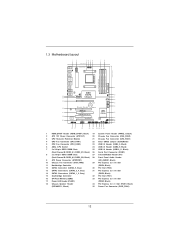
...Express 2.0 x16 Slot 17 Power LED Header (PLED1) (PCIE2; Black) 18 Chassis Speaker Header 34 PCI Express 2.0 x1 Slot (PCIE1; 1.3 Motherboard Layout 12 34 5 6 21.8cm (8.6-in) Designed in Taipei 1 HDMI_SPDIF1 ATX12V1 CPU_FAN1 CPU_FAN2 PS2 Mouse PS2 Keyboard Coaxial SPDIF Optical SPDIF 78...: LINE IN Center: FRONT Bottom: MIC IN LAN PHY PWR_FAN1 PCIE1 AMD 990FX Chipset CHA_FAN3 SATA3_5 SATA3_3_4 PCIE2 RoHS SATA3_1_2 CMOS BATTERY XFast LAN XFast USB USB 3.0 AUDIO CODEC PCI1 PCIE3 990FX Extreme3 AMD SB950 Chipset Super I/O PCI2 Support 8-Core CPU SATA3 6Gb/s ErP/EuP...
...Express 2.0 x16 Slot 17 Power LED Header (PLED1) (PCIE2; Black) 18 Chassis Speaker Header 34 PCI Express 2.0 x1 Slot (PCIE1; 1.3 Motherboard Layout 12 34 5 6 21.8cm (8.6-in) Designed in Taipei 1 HDMI_SPDIF1 ATX12V1 CPU_FAN1 CPU_FAN2 PS2 Mouse PS2 Keyboard Coaxial SPDIF Optical SPDIF 78...: LINE IN Center: FRONT Bottom: MIC IN LAN PHY PWR_FAN1 PCIE1 AMD 990FX Chipset CHA_FAN3 SATA3_5 SATA3_3_4 PCIE2 RoHS SATA3_1_2 CMOS BATTERY XFast LAN XFast USB USB 3.0 AUDIO CODEC PCI1 PCIE3 990FX Extreme3 AMD SB950 Chipset Super I/O PCI2 Support 8-Core CPU SATA3 6Gb/s ErP/EuP...

User Manual
Page 15
... Hold components by the edges and do so may damage the motherboard. 15 Before you install or remove any motherboard settings. 2. To avoid damaging the motherboard's components due to static electricity, NEVER place your chassis to the motherboard, peripherals, and/or components. 1. When placing screws into it.... Unplug the power cord from the power supply. Pre-installation Precautions Take note of your motherboard directly on a grounded antistatic pad or in , 30.5 cm x 21.8 cm) motherboard. Doing so may cause severe damage to ensure that the power is switched off or the...
... Hold components by the edges and do so may damage the motherboard. 15 Before you install or remove any motherboard settings. 2. To avoid damaging the motherboard's components due to static electricity, NEVER place your chassis to the motherboard, peripherals, and/or components. 1. When placing screws into it.... Unplug the power cord from the power supply. Pre-installation Precautions Take note of your motherboard directly on a grounded antistatic pad or in , 30.5 cm x 21.8 cm) motherboard. Doing so may cause severe damage to ensure that the power is switched off or the...

User Manual
Page 16
... the CPU fan and the heatsink. 16 Unlock the socket by lifting the lever up to dissipate heat. DO NOT force the CPU into this motherboard, it firmly on the side tab to the instruction manuals of the pins. 2.1 CPU Installation o Step 1. Step 2. When the CPU is necessary to install...
... the CPU fan and the heatsink. 16 Unlock the socket by lifting the lever up to dissipate heat. DO NOT force the CPU into this motherboard, it firmly on the side tab to the instruction manuals of the pins. 2.1 CPU Installation o Step 1. Step 2. When the CPU is necessary to install...

User Manual
Page 17
... DDR3 DIMMs in the set of slots DDR3_A1 and DDR3_B1, or in all four slots. Please install the memory module into DDR3 slot; This motherboard also allows you to the Dual Channel Memory Configuration Table below. Populated - In other words, you always need to activate the Dual...slots. If only one memory module or three memory modules are installed in the DDR3 DIMM slots on DDR3_A2 and DDR3_B2 slots. 17 otherwise, this motherboard, it is not allowed to install identical DDR3 DIMM pair in Dual Channel B (DDR3_A2 and DDR3_ B2; If you want to install two ...
... DDR3 DIMMs in the set of slots DDR3_A1 and DDR3_B1, or in all four slots. Please install the memory module into DDR3 slot; This motherboard also allows you to the Dual Channel Memory Configuration Table below. Populated - In other words, you always need to activate the Dual...slots. If only one memory module or three memory modules are installed in the DDR3 DIMM slots on DDR3_A2 and DDR3_B2 slots. 17 otherwise, this motherboard, it is not allowed to install identical DDR3 DIMM pair in Dual Channel B (DDR3_A2 and DDR3_ B2; If you want to install two ...

User Manual
Page 18
... 2. Step 3. Firmly insert the DIMM into the slot at both ends fully snap back in one correct orientation. Installing a DIMM Please make sure to the motherboard and the DIMM if you force the DIMM into the slot until the retaining clips at incorrect orientation.
... 2. Step 3. Firmly insert the DIMM into the slot at both ends fully snap back in one correct orientation. Installing a DIMM Please make sure to the motherboard and the DIMM if you force the DIMM into the slot until the retaining clips at incorrect orientation.

User Manual
Page 19
...Express x16 graphics cards on PCIE2, PCIE3 and PCIE4 slots. Installing an expansion card Step 1. Step 2. Remove the system unit cover (if your motherboard is used to install PCI Express graphics cards to support 3-Way CrossFireXTM function. 1. Step 4. Fasten the card to use . PCIE4 (PCIE ...power cord is completely seated on PCIE2 slot. 2. Step 6. Black) is used for PCI Express x16 lane width graphics cards, or used to motherboard chassis fan connector (CHA_FAN1, CHA_FAN2 or CHA_FAN3) when using multiple graphics cards for later use . Step 3. 2.4 Expansion Slots (PCI and PCI...
...Express x16 graphics cards on PCIE2, PCIE3 and PCIE4 slots. Installing an expansion card Step 1. Step 2. Remove the system unit cover (if your motherboard is used to install PCI Express graphics cards to support 3-Way CrossFireXTM function. 1. Step 4. Fasten the card to use . PCIE4 (PCIE ...power cord is completely seated on PCIE2 slot. 2. Step 6. Black) is used for PCI Express x16 lane width graphics cards, or used to motherboard chassis fan connector (CHA_FAN1, CHA_FAN2 or CHA_FAN3) when using multiple graphics cards for later use . Step 3. 2.4 Expansion Slots (PCI and PCI...

User Manual
Page 20
... that are NVIDIA® certified. 2. Please refer to three identical PCI Express x16 graphics cards. Step2. 2.5 SLITM and Quad SLITM Operation Guide This motherboard supports NVIDIA® SLITM and Quad SLITM (Scalable Link Interface) technology that allows you to install up to NVIDIA® website for details. 2.5.1 Graphics Card...
... that are NVIDIA® certified. 2. Please refer to three identical PCI Express x16 graphics cards. Step2. 2.5 SLITM and Quad SLITM Operation Guide This motherboard supports NVIDIA® SLITM and Quad SLITM (Scalable Link Interface) technology that allows you to install up to NVIDIA® website for details. 2.5.1 Graphics Card...

User Manual
Page 23
... the AMD website for detailed installation guides. 2.6 CrossFireXTM, 3-Way CrossFireXTM and Quad CrossFireXTM Operation Guide This motherboard supports CrossFireXTM, 3-way CrossFireXTM and Quad CrossFireXTM features. If you pair a 12-pipe CrossFireXTM Edition card ..., CrossFireXTM enables the highest possible level of CrossFireXTM. All three CrossFireXTM components, a CrossFireXTM Ready graphics card, a CrossFireXTM Ready motherboard and a CrossFireXTM Edition co-processor graphics card, must be installed correctly to AMDTM graphics card manuals for AMDTM CrossFireXTM driver updates...
... the AMD website for detailed installation guides. 2.6 CrossFireXTM, 3-Way CrossFireXTM and Quad CrossFireXTM Operation Guide This motherboard supports CrossFireXTM, 3-way CrossFireXTM and Quad CrossFireXTM features. If you pair a 12-pipe CrossFireXTM Edition card ..., CrossFireXTM enables the highest possible level of CrossFireXTM. All three CrossFireXTM components, a CrossFireXTM Ready graphics card, a CrossFireXTM Ready motherboard and a CrossFireXTM Edition co-processor graphics card, must be installed correctly to AMDTM graphics card manuals for AMDTM CrossFireXTM driver updates...

User Manual
Page 24
... to the DVI connector on the top of Radeon graphics cards. (CrossFire Bridge is provided with the graphics card you purchase, not bundled with this motherboard. Connect two Radeon graphics cards by installing CrossFire Bridge on CrossFire Bridge Interconnects on the Radeon graphics card in the PCIE2 slot. (You may use...
... to the DVI connector on the top of Radeon graphics cards. (CrossFire Bridge is provided with the graphics card you purchase, not bundled with this motherboard. Connect two Radeon graphics cards by installing CrossFire Bridge on CrossFire Bridge Interconnects on the Radeon graphics card in the PCIE2 slot. (You may use...

User Manual
Page 25
... refer to connect Radeon graphics cards on PCIE3 and PCIE4 slots. (CrossFireTM Bridge is provided with the graphics card you purchase, not bundled with this motherboard. Use one Radeon graphics card to your graphics card vendor for details.) 25 Step 3. Please refer to the PCIE2 slot. Install one CrossFireTM Bridge to...
... refer to connect Radeon graphics cards on PCIE3 and PCIE4 slots. (CrossFireTM Bridge is provided with the graphics card you purchase, not bundled with this motherboard. Use one Radeon graphics card to your graphics card vendor for details.) 25 Step 3. Please refer to the PCIE2 slot. Install one CrossFireTM Bridge to...

User Manual
Page 28
Although you are able to infringe. * For further information of AMDTM CrossFireXTM technology, please check AMD website for updates and details. 2.7 Surround Display Feature This motherboard supports Surround Display upgrade. For the detailed instruction, please refer to the document at the following path in "ATI Catalyst Control Center" is used only ...
Although you are able to infringe. * For further information of AMDTM CrossFireXTM technology, please check AMD website for updates and details. 2.7 Surround Display Feature This motherboard supports Surround Display upgrade. For the detailed instruction, please refer to the document at the following path in "ATI Catalyst Control Center" is used only ...

User Manual
Page 30
...transfer rate. Serial ATA3 Connectors (SATA3_1_2: see p.12, No. 14) (SATA3_3_4: see p.12, No. 13) (SATA3_5: see p.12 No. 24) Either end of the motherboard! Each USB 2.0 header can be connected to the SATA3 hard disk or the SATA3 connector on this... motherboard. 2.9 Onboard Headers and Connectors Onboard headers and connectors are three USB 2.0 headers on this motherboard. Placing jumper caps over these headers and connectors. The current SATA3 interface allows up to the portable audio ...
...transfer rate. Serial ATA3 Connectors (SATA3_1_2: see p.12, No. 14) (SATA3_3_4: see p.12, No. 13) (SATA3_5: see p.12 No. 24) Either end of the motherboard! Each USB 2.0 header can be connected to the SATA3 hard disk or the SATA3 connector on this... motherboard. 2.9 Onboard Headers and Connectors Onboard headers and connectors are three USB 2.0 headers on this motherboard. Placing jumper caps over these headers and connectors. The current SATA3 interface allows up to the portable audio ...

User Manual
Page 33
...FAN_SPEED_CONTROL (see p.12 No. 20) Please connect the fan cables to the fan connectors and match the black wire to this connector. 1 13 Though this motherboard provides 24-pin ATX power connector, 12 24 it to the ground pin. Pin 1-3 Connected 3-Pin Fan Installation (3-pin CPU_FAN2) (see p.12 No....Supply Installation 1 13 33 CHA_FAN1/2/3 fan speed can work if you plan to connect the 3-Pin CPU fan to the CPU fan connector on this motherboard provides 4-Pin CPU fan (Quiet Fan) support, the 3-Pin CPU fan still can be controlled through UEFI or AXTU. (3-pin CHA_FAN3) (see ...
...FAN_SPEED_CONTROL (see p.12 No. 20) Please connect the fan cables to the fan connectors and match the black wire to this connector. 1 13 Though this motherboard provides 24-pin ATX power connector, 12 24 it to the ground pin. Pin 1-3 Connected 3-Pin Fan Installation (3-pin CPU_FAN2) (see p.12 No....Supply Installation 1 13 33 CHA_FAN1/2/3 fan speed can work if you plan to connect the 3-Pin CPU fan to the CPU fan connector on this motherboard provides 4-Pin CPU fan (Quiet Fan) support, the 3-Pin CPU fan still can be controlled through UEFI or AXTU. (3-pin CHA_FAN3) (see ...

User Manual
Page 34
... 5. 5 1 Serial port Header (9-pin COM1) (see p.12 No.26) HDMI_SPDIF Header (2-pin HDMI_SPDIF1) (see p.12 No. 2) 8 4 Please connect an ATX 12V power supply to this motherboard provides 8-pin ATX 12V power connector, it can still work if you adopt a traditional 4-pin ATX 12V power supply. ATX 12V Power Connector 5 1 (8-pin ATX12V1...
... 5. 5 1 Serial port Header (9-pin COM1) (see p.12 No.26) HDMI_SPDIF Header (2-pin HDMI_SPDIF1) (see p.12 No. 2) 8 4 Please connect an ATX 12V power supply to this motherboard provides 8-pin ATX 12V power connector, it can still work if you adopt a traditional 4-pin ATX 12V power supply. ATX 12V Power Connector 5 1 (8-pin ATX12V1...


