
User Manual
Page 5
....5 cm x 21.8 cm) ASRock 990FX Extreme3 Quick Installation Guide ASRock 990FX Extreme3 Support CD 1 x ASRock SLI_Bridge_2S Card 2 x Serial ATA (SATA) Data Cables (Optional) 1 x 3.5mm Audio Cable (Optional) 1 x I/O Panel Shield ASRock Reminds You... It delivers excellent performance with robust design conforming to ASRock's commitment to AHCI mode. Chapter 3 and 4 contain the configuration guide to BIOS setup and information of...
....5 cm x 21.8 cm) ASRock 990FX Extreme3 Quick Installation Guide ASRock 990FX Extreme3 Support CD 1 x ASRock SLI_Bridge_2S Card 2 x Serial ATA (SATA) Data Cables (Optional) 1 x 3.5mm Audio Cable (Optional) 1 x I/O Panel Shield ASRock Reminds You... It delivers excellent performance with robust design conforming to ASRock's commitment to AHCI mode. Chapter 3 and 4 contain the configuration guide to BIOS setup and information of...

User Manual
Page 7
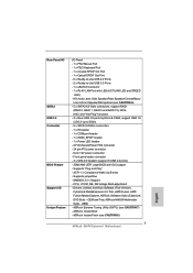
... Suite - OEM) 7 Supports "Plug and Play" - CPU, VCCM, NB, SB Voltage Multi-adjustment - Supports jumperfree - ACPI 1.1 Compliance Wake Up Events - ASRock MAGIX Multimedia Suite - OEM and Trial; Rear Panel I/O SATA3 USB 3.0 Connector BIOS Feature Support CD I/O Panel - 1 x PS/2 Mouse Port - 1 x PS/2 Keyboard Port - 1 x Coaxial SPDIF Out Port - 1 x Optical SPDIF Out Port - ... - 24 pin ATX power connector - 8 pin 12V power connector - Front panel audio connector - 3 x USB 2.0 headers (support 6 USB 2.0 ports) - 32Mb AMI UEFI Legal BIOS with LED (ACT/LINK LED and SPEED LED) -
... Suite - OEM) 7 Supports "Plug and Play" - CPU, VCCM, NB, SB Voltage Multi-adjustment - Supports jumperfree - ACPI 1.1 Compliance Wake Up Events - ASRock MAGIX Multimedia Suite - OEM and Trial; Rear Panel I/O SATA3 USB 3.0 Connector BIOS Feature Support CD I/O Panel - 1 x PS/2 Mouse Port - 1 x PS/2 Keyboard Port - 1 x Coaxial SPDIF Out Port - 1 x Optical SPDIF Out Port - ... - 24 pin ATX power connector - 8 pin 12V power connector - Front panel audio connector - 3 x USB 2.0 headers (support 6 USB 2.0 ports) - 32Mb AMI UEFI Legal BIOS with LED (ACT/LINK LED and SPEED LED) -

User Manual
Page 9
... Technology. Before you adopt. It should be noted that there is a certain risk involved with AM3 CPU only, and in the BIOS, applying Untied Overclocking Technology, or using third-party overclocking tools. Due to the operating system limitation, the actual memory size may affect... your OC settings as a profile and 9 For microphone input, this motherboard supports both stereo and mono modes. ASRock Extreme Tuning Utility (AXTU) is supported with overclocking, including adjusting the setting in addition, not every AM3 CPU can support this function because...
... Technology. Before you adopt. It should be noted that there is a certain risk involved with AM3 CPU only, and in the BIOS, applying Untied Overclocking Technology, or using third-party overclocking tools. Due to the operating system limitation, the actual memory size may affect... your OC settings as a profile and 9 For microphone input, this motherboard supports both stereo and mono modes. ASRock Extreme Tuning Utility (AXTU) is supported with overclocking, including adjusting the setting in addition, not every AM3 CPU can support this function because...

User Manual
Page 10
...priority higher, it makes your iPhone charge much quickly from your BIOS only in Flash ROM. ASRock APP Charger allows you can update your computer and up to update system BIOS without sacrificing computing performance. ASRock SmartView, a new function for you to 40% faster than before.... To use FAT32/16/12 file system. 9. ASRock website: http://www.asrock.com/Feature/SmartView/index.asp 11. Real-...
...priority higher, it makes your iPhone charge much quickly from your BIOS only in Flash ROM. ASRock APP Charger allows you can update your computer and up to update system BIOS without sacrificing computing performance. ASRock SmartView, a new function for you to 40% faster than before.... To use FAT32/16/12 file system. 9. ASRock website: http://www.asrock.com/Feature/SmartView/index.asp 11. Real-...
User Manual
Page 12
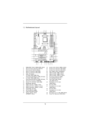
...LINE IN Center: FRONT Bottom: MIC IN LAN PHY PWR_FAN1 PCIE1 AMD 990FX Chipset CHA_FAN3 SATA3_5 SATA3_3_4 PCIE2 RoHS SATA3_1_2 CMOS BATTERY XFast LAN XFast USB USB 3.0 AUDIO CODEC PCI1 PCIE3 990FX Extreme3 AMD SB950 Chipset Super I/O PCI2 Support 8-Core CPU SATA3 6Gb/s ErP.../EuP Ready HD_AUDIO1 1 IR1 1 PCIE4 COM1 USB10_11 USB8_9 1 1 USB4_5 1 32Mb BIOS PLED1 1 CHA_FAN1 CLRCMOS1 1 CHA_FAN2 1 SPEAKER1 PANEL 1 PLED ...
...LINE IN Center: FRONT Bottom: MIC IN LAN PHY PWR_FAN1 PCIE1 AMD 990FX Chipset CHA_FAN3 SATA3_5 SATA3_3_4 PCIE2 RoHS SATA3_1_2 CMOS BATTERY XFast LAN XFast USB USB 3.0 AUDIO CODEC PCI1 PCIE3 990FX Extreme3 AMD SB950 Chipset Super I/O PCI2 Support 8-Core CPU SATA3 6Gb/s ErP.../EuP Ready HD_AUDIO1 1 IR1 1 PCIE4 COM1 USB10_11 USB8_9 1 1 USB4_5 1 32Mb BIOS PLED1 1 CHA_FAN1 CLRCMOS1 1 CHA_FAN2 1 SPEAKER1 PANEL 1 PLED ...

User Manual
Page 29
... CMOS Jumper (CLRCMOS1) (see p.12, No. 22) Default Clear CMOS Note: CLRCMOS1 allows you to clear the CMOS when you just finished updating the BIOS, you must boot up the system first, and then shut it down before you do not clear the CMOS right after you need to... system setup information such as system password, date, time, and system setup parameters. The data in CMOS. After waiting for 5 seconds. If you update the BIOS. However, please do the clear-CMOS action. 29 To clear and reset the system parameters to short pin2 and pin3 on pins, the jumper is...
... CMOS Jumper (CLRCMOS1) (see p.12, No. 22) Default Clear CMOS Note: CLRCMOS1 allows you to clear the CMOS when you just finished updating the BIOS, you must boot up the system first, and then shut it down before you do not clear the CMOS right after you need to... system setup information such as system password, date, time, and system setup parameters. The data in CMOS. After waiting for 5 seconds. If you update the BIOS. However, please do the clear-CMOS action. 29 To clear and reset the system parameters to short pin2 and pin3 on pins, the jumper is...

User Manual
Page 39
...: .. \ RAID Installation Guide STEP 3: Make a SATA3 Driver Diskette. A. Enter UEFI SETUP UTILITY Advanced screen Storage Configuration. STEP 2: Use "RAID Installation Guide" to the BIOS RAID installation guide part of Windows® setup, press F6 to [RAID]. Before you start to set RAID configuration. Please refer to install... AMD RAID driver. Before you start to configure RAID function, you can start to configure RAID function, you want to the BIOS RAID installation guide part of 2 or more SATA3 HDDs with RAID functions, please follow below steps.
...: .. \ RAID Installation Guide STEP 3: Make a SATA3 Driver Diskette. A. Enter UEFI SETUP UTILITY Advanced screen Storage Configuration. STEP 2: Use "RAID Installation Guide" to the BIOS RAID installation guide part of Windows® setup, press F6 to [RAID]. Before you start to set RAID configuration. Please refer to install... AMD RAID driver. Before you start to configure RAID function, you can start to configure RAID function, you want to the BIOS RAID installation guide part of 2 or more SATA3 HDDs with RAID functions, please follow below steps.

User Manual
Page 62
... use Windows® VistaTM 64-bit (with SP1 or above) or Windows® 7 64-bit. 2. Set AHCI Mode in AHCI Mode This motherboard adopts UEFI BIOS that allows Windows® OS to boot. 4. Start Windows® installation. 62 Installing OS on a large size HDD (>2TB). Choose the item "UEFI:xxx" to...
... use Windows® VistaTM 64-bit (with SP1 or above) or Windows® 7 64-bit. 2. Set AHCI Mode in AHCI Mode This motherboard adopts UEFI BIOS that allows Windows® OS to boot. 4. Start Windows® installation. 62 Installing OS on a large size HDD (>2TB). Choose the item "UEFI:xxx" to...

User Manual
Page 63
... (>2TB). Key in drvcfg, for example: key in dh 4E. 63 Installing OS on a HDD Larger Than 2TB in RAID Mode This motherboard adopts UEFI BIOS that allows Windows® OS to save the change and exit. 4. Please make sure to enter Boot Manual. Please follow the procedures below : Drv[4E...
... (>2TB). Key in drvcfg, for example: key in dh 4E. 63 Installing OS on a HDD Larger Than 2TB in RAID Mode This motherboard adopts UEFI BIOS that allows Windows® OS to save the change and exit. 4. Please make sure to enter Boot Manual. Please follow the procedures below : Drv[4E...

Quick Installation Guide
Page 2
... XFast LAN XFast USB USB 3.0 AUDIO CODEC PCI1 PCIE3 990FX Extreme3 AMD SB950 Chipset Super I/O PCI2 Support 8-Core CPU SATA3 6Gb/s ErP/EuP Ready HD_AUDIO1 1 IR1 1 PCIE4 COM1 USB10_11 USB8_9 1 1 USB4_5 1 32Mb BIOS PLED1 1 CHA_FAN1 CLRCMOS1 1 CHA_FAN2 1 SPEAKER1 PANEL 1 ...PCI Express 2.0 x16 Slot 17 Power LED Header (PLED1) (PCIE2; Black) (SPEAKER 1, Black) 35 Power Fan Connector (PWR_FAN1) 2 ASRock 990FX Extreme3 Motherboard English Black) 28 Front Panel Audio Header 9 ATX Power Connector (ATXPWR1) (HD_AUDIO1, Black) 10 Chassis Fan Connector (CHA_FAN3) 29 PCI...
... XFast LAN XFast USB USB 3.0 AUDIO CODEC PCI1 PCIE3 990FX Extreme3 AMD SB950 Chipset Super I/O PCI2 Support 8-Core CPU SATA3 6Gb/s ErP/EuP Ready HD_AUDIO1 1 IR1 1 PCIE4 COM1 USB10_11 USB8_9 1 1 USB4_5 1 32Mb BIOS PLED1 1 CHA_FAN1 CLRCMOS1 1 CHA_FAN2 1 SPEAKER1 PANEL 1 ...PCI Express 2.0 x16 Slot 17 Power LED Header (PLED1) (PCIE2; Black) (SPEAKER 1, Black) 35 Power Fan Connector (PWR_FAN1) 2 ASRock 990FX Extreme3 Motherboard English Black) 28 Front Panel Audio Header 9 ATX Power Connector (ATXPWR1) (HD_AUDIO1, Black) 10 Chassis Fan Connector (CHA_FAN3) 29 PCI...

Quick Installation Guide
Page 5
...this motherboard, please visit our website for specific information about the model you for details. 5 ASRock 990FX Extreme3 Motherboard English For the BIOS setup, please refer to AHCI mode. More detailed information of this manual will be found in the ...VistaTM / VistaTM 64 bit, it is recommended to set the BIOS option in Storage Configuration to the "User Manual" in our support CD for purchasing ASRock 990FX Extreme3 motherboard, a reliable motherboard produced under ASRock's consistently stringent quality control. This Quick Installation Guide contains introduction...
...this motherboard, please visit our website for specific information about the model you for details. 5 ASRock 990FX Extreme3 Motherboard English For the BIOS setup, please refer to AHCI mode. More detailed information of this manual will be found in the ...VistaTM / VistaTM 64 bit, it is recommended to set the BIOS option in Storage Configuration to the "User Manual" in our support CD for purchasing ASRock 990FX Extreme3 motherboard, a reliable motherboard produced under ASRock's consistently stringent quality control. This Quick Installation Guide contains introduction...
Quick Installation Guide
Page 7
... UEFI Legal BIOS with LED (ACT/LINK LED and SPEED LED) - OEM and Trial; CPU/Chassis/Power FAN connector - 24 pin ATX power connector - 8 pin 12V power connector - ASRock Instant Boot - ASRock MAGIX Multimedia Suite - Supports "Plug and Play" - OEM) - ASRock Extreme Tuning ... (see CAUTION 7) - CPU, VCCM, NB, SB Voltage Multi-adjustment - Supports jumperfree - ASRock Instant Flash (see CAUTION 8) English 7 ASRock 990FX Extreme3 Motherboard SMBIOS 2.3.1 Support - Drivers, Utilities, AntiVirus Software (Trial Version), CyberLink MediaEspresso 6.5 Trial, AMD Fusion...
... UEFI Legal BIOS with LED (ACT/LINK LED and SPEED LED) - OEM and Trial; CPU/Chassis/Power FAN connector - 24 pin ATX power connector - 8 pin 12V power connector - ASRock Instant Boot - ASRock MAGIX Multimedia Suite - Supports "Plug and Play" - OEM) - ASRock Extreme Tuning ... (see CAUTION 7) - CPU, VCCM, NB, SB Voltage Multi-adjustment - Supports jumperfree - ASRock Instant Flash (see CAUTION 8) English 7 ASRock 990FX Extreme3 Motherboard SMBIOS 2.3.1 Support - Drivers, Utilities, AntiVirus Software (Trial Version), CyberLink MediaEspresso 6.5 Trial, AMD Fusion...

Quick Installation Guide
Page 9
...64257;es AMD CPU activation. Whether 2100MHz memory speed is supported depends on our website for the compatible memory modules. ASRock website http://www.asrock.com 5. In Hardware Monitor, it with your system. In OC DNA, you can unlock the extra CPU core to... 4. Via a simple switch in the BIOS, applying Untied Overclocking Technology, or using third-party overclocking tools. Please check the table on page 33 for details. 3. CAUTION! 1. If you can load the OC profile to 9 ASRock 990FX Extreme3 Motherboard English This motherboard supports Untied Overclocking Technology...
...64257;es AMD CPU activation. Whether 2100MHz memory speed is supported depends on our website for the compatible memory modules. ASRock website http://www.asrock.com 5. In Hardware Monitor, it with your system. In OC DNA, you can unlock the extra CPU core to... 4. Via a simple switch in the BIOS, applying Untied Overclocking Technology, or using third-party overclocking tools. Please check the table on page 33 for details. 3. CAUTION! 1. If you can load the OC profile to 9 ASRock 990FX Extreme3 Motherboard English This motherboard supports Untied Overclocking Technology...

Quick Installation Guide
Page 10
... Flash. In IES (Intelligent Energy Saver), the voltage regulator can update your PC enters into the BIOS setup menu to get the same OC settings. Just launch this utility, you are transferring currently. 10 ASRock 990FX Extreme3 Motherboard English Simply install the APP Charger driver, it can press the key during the POST or...
... Flash. In IES (Intelligent Energy Saver), the voltage regulator can update your PC enters into the BIOS setup menu to get the same OC settings. Just launch this utility, you are transferring currently. 10 ASRock 990FX Extreme3 Motherboard English Simply install the APP Charger driver, it can press the key during the POST or...

Quick Installation Guide
Page 26
...are "Short" when jumper cap is placed on these 2 pins. The illustration shows a 3-pin jumper whose pin1 and pin2 are setup. English 26 ASRock 990FX Extreme3 Motherboard When the jumper cap is placed on pins, the jumper is removed. After waiting for 15 seconds, use a jumper cap to default setup, ... from the power supply. Jumper Setting Clear CMOS Jumper (CLRCMOS1) (see p.2, No. 22) Default Clear CMOS Note: CLRCMOS1 allows you update the BIOS. The data in CMOS. To clear and reset the system parameters to short pin2 and pin3 on pins, the jumper is "Open". Please be ...
...are "Short" when jumper cap is placed on these 2 pins. The illustration shows a 3-pin jumper whose pin1 and pin2 are setup. English 26 ASRock 990FX Extreme3 Motherboard When the jumper cap is placed on pins, the jumper is removed. After waiting for 15 seconds, use a jumper cap to default setup, ... from the power supply. Jumper Setting Clear CMOS Jumper (CLRCMOS1) (see p.2, No. 22) Default Clear CMOS Note: CLRCMOS1 allows you update the BIOS. The data in CMOS. To clear and reset the system parameters to short pin2 and pin3 on pins, the jumper is "Open". Please be ...
Quick Installation Guide
Page 34
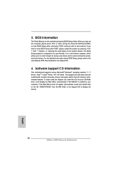
..., please press or during the Power-On-Self-Test (POST) to be user-friendly. For the detailed information about BIOS Setup, please refer to enter BIOS Setup after POST, please restart the system by pressing + + , or pressing the reset button on the system chassis...Menu does not appear automatically, locate and double-click on the motherboard stores BIOS Setup Utility. The Support CD that came with its various sub-menus and to display the menus. 34 ASRock 990FX Extreme3 Motherboard English Software Support CD information This motherboard supports various Microsoft® ...
..., please press or during the Power-On-Self-Test (POST) to be user-friendly. For the detailed information about BIOS Setup, please refer to enter BIOS Setup after POST, please restart the system by pressing + + , or pressing the reset button on the system chassis...Menu does not appear automatically, locate and double-click on the motherboard stores BIOS Setup Utility. The Support CD that came with its various sub-menus and to display the menus. 34 ASRock 990FX Extreme3 Motherboard English Software Support CD information This motherboard supports various Microsoft® ...

Quick Installation Guide
Page 126
1.3 그림은 3 1-2 쇼트 오픈 점퍼 CMOS 초기화 (CLRCMOS1, 3 2 22 세팅 CMOS 삭제 참고 : CLRCMOS1 CMOS 15 CLRCMOS1 의 핀 2 와 핀 3 을 5 BIOS CMOS BIOS CMOS CMOS CMOS 1394 GUID, MAC 한 국 어 126 ASRock 990FX Extreme3 Motherboard
1.3 그림은 3 1-2 쇼트 오픈 점퍼 CMOS 초기화 (CLRCMOS1, 3 2 22 세팅 CMOS 삭제 참고 : CLRCMOS1 CMOS 15 CLRCMOS1 의 핀 2 와 핀 3 을 5 BIOS CMOS BIOS CMOS CMOS CMOS 1394 GUID, MAC 한 국 어 126 ASRock 990FX Extreme3 Motherboard

Quick Installation Guide
Page 137
...;ット CPU の Windows® OS 6. 2 4 6 8 3 ださい。 7. BIOS 注意 1. ASRock UCC (Unlock CPU Core CPU AMD CPU UEFI nlock CPU Core CPU CPU UCC CPU CPU に引き CPU... OC DDR3 1866 は AM3+ CPU ASRock Web サイト http://www.asrock.com 5. ASRock Extreme Tuning Utility (AXTU OC DNA、IES CPU OC DNA OC 設定 OC OC IES CPU ASRock 137 ASRock 990FX Extreme3 Motherboard 日本語
...;ット CPU の Windows® OS 6. 2 4 6 8 3 ださい。 7. BIOS 注意 1. ASRock UCC (Unlock CPU Core CPU AMD CPU UEFI nlock CPU Core CPU CPU UCC CPU CPU に引き CPU... OC DDR3 1866 は AM3+ CPU ASRock Web サイト http://www.asrock.com 5. ASRock Extreme Tuning Utility (AXTU OC DNA、IES CPU OC DNA OC 設定 OC OC IES CPU ASRock 137 ASRock 990FX Extreme3 Motherboard 日本語

Quick Installation Guide
Page 138
ASRock Instant Flash は、Flash ROM ROM BIOS BIOS MS-DOS Windows BIOS POST の間に Extreme Tuning Utility (AXTU Web ASRock Web サイト :http://www.asrock.com 8.
ASRock Instant Flash は、Flash ROM ROM BIOS BIOS MS-DOS Windows BIOS POST の間に Extreme Tuning Utility (AXTU Web ASRock Web サイト :http://www.asrock.com 8.

Quick Installation Guide
Page 140
1.3 1-2 ショート CMOS CLRCMOS1 22 参照) 設定 説明 CMOS の消去 オープン 注 : CLRCMOS1 CMOS 15 CLRCMOS1 のピン 2 とピン 3 を 5 BIOS CMOS BIOS CMOS CMOS 1394 GUID と MAC CMOS 日本語 140 ASRock 990FX Extreme3 Motherboard
1.3 1-2 ショート CMOS CLRCMOS1 22 参照) 設定 説明 CMOS の消去 オープン 注 : CLRCMOS1 CMOS 15 CLRCMOS1 のピン 2 とピン 3 を 5 BIOS CMOS BIOS CMOS CMOS 1394 GUID と MAC CMOS 日本語 140 ASRock 990FX Extreme3 Motherboard


