RAID Installation Guide
Page 3
... JBOD. Please use two drives of your future data building will be the base storage size for the RAID 1 set up to the PC's motherboard controller. You may use two new drives, or use two drives of 2 or more than the existing drive). If you use an existing drive...Ready. 1.2 RAID Configurations Precautions 1. For example, if one physical drive. It is recommended to four of the same size or larger than most PC motherboards. If you install. 3 A RAID Ready logical drive has only one hard disk has an 80GB storage capacity and the other RAID logical drives. You...
... JBOD. Please use two drives of your future data building will be the base storage size for the RAID 1 set up to the PC's motherboard controller. You may use two new drives, or use two drives of 2 or more than the existing drive). If you use an existing drive...Ready. 1.2 RAID Configurations Precautions 1. For example, if one physical drive. It is recommended to four of the same size or larger than most PC motherboards. If you install. 3 A RAID Ready logical drive has only one hard disk has an 80GB storage capacity and the other RAID logical drives. You...
User Manual
Page 2
...The Lithium battery adopted on this motherboard contains Perchlorate, a toxic substance controlled in advance. "Perchlorate Material-special handling may apply, see www.dtsc.ca.gov/hazardouswaste/perchlorate" ASRock Website: http://www.asrock.com 2 ASRock assumes no event shall ASRock, its directors, officers, employees,... operation. Disclaimer: Specifications and information contained in any form or by any means, except duplication of documentation by ASRock. Copyright Notice: No part of this manual may be reproduced, transcribed, transmitted, or translated in any language,...
...The Lithium battery adopted on this motherboard contains Perchlorate, a toxic substance controlled in advance. "Perchlorate Material-special handling may apply, see www.dtsc.ca.gov/hazardouswaste/perchlorate" ASRock Website: http://www.asrock.com 2 ASRock assumes no event shall ASRock, its directors, officers, employees,... operation. Disclaimer: Specifications and information contained in any form or by any means, except duplication of documentation by ASRock. Copyright Notice: No part of this manual may be reproduced, transcribed, transmitted, or translated in any language,...
User Manual
Page 3
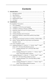
Introduction 5 1.1 Package Contents 5 1.2 Specifications 6 1.3 Unique Features 9 1.4 Motherboard Layout 12 1.5 I/O Panel 13 2. Installation 14 Pre-installation Precautions 14 2.1 CPU Installation 15 2.2 Installation of CPU Fan and Heatsink 15 2.3 Installation of Memory Modules (DIMM ...
Introduction 5 1.1 Package Contents 5 1.2 Specifications 6 1.3 Unique Features 9 1.4 Motherboard Layout 12 1.5 I/O Panel 13 2. Installation 14 Pre-installation Precautions 14 2.1 CPU Installation 15 2.2 Installation of CPU Fan and Heatsink 15 2.3 Installation of Memory Modules (DIMM ...
User Manual
Page 5
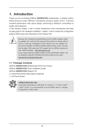
... and the BIOS software might be updated, the content of the Support CD. www.asrock.com/support/index.asp 1.1 Package Contents ASRock 980DE3/U3S3 Motherboard (ATX Form Factor) ASRock 980DE3/U3S3 Quick Installation Guide ASRock 980DE3/U3S3 Support CD 2 x Serial ATA (SATA) Data Cables (Optional) 1 x I/O Panel Shield ASRock Reminds You... Introduction Thank you are using. You may find the latest VGA cards...
... and the BIOS software might be updated, the content of the Support CD. www.asrock.com/support/index.asp 1.1 Package Contents ASRock 980DE3/U3S3 Motherboard (ATX Form Factor) ASRock 980DE3/U3S3 Quick Installation Guide ASRock 980DE3/U3S3 Support CD 2 x Serial ATA (SATA) Data Cables (Optional) 1 x I/O Panel Shield ASRock Reminds You... Introduction Thank you are using. You may find the latest VGA cards...

User Manual
Page 8
...even cause damage to the memory support list on the AM3/AM3+ CPU you want to adopt DDR3 1866/1600 memory module on this motherboard, please refer to the components and devices of your own risk and expense. CPU/Chassis/Power Fan Multi-Speed Control - Voltage Monitoring:... +12V, +5V, +3.3V, Vcore OS - ASRock website: http://www.asrock.com 2. We are not responsible for the compatible memory modules. Microsoft® Windows® 8 / 8 64-bit / 7 / 7 64-bit / ...
...even cause damage to the memory support list on the AM3/AM3+ CPU you want to adopt DDR3 1866/1600 memory module on this motherboard, please refer to the components and devices of your own risk and expense. CPU/Chassis/Power Fan Multi-Speed Control - Voltage Monitoring:... +12V, +5V, +3.3V, Vcore OS - ASRock website: http://www.asrock.com 2. We are not responsible for the compatible memory modules. Microsoft® Windows® 8 / 8 64-bit / 7 / 7 64-bit / ...
User Manual
Page 10
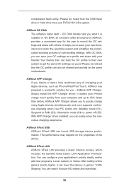
... off (S5). OC DNA literally tells you - It helps you to save your OC settings as a profile and share with others. ASRock APP Charger allows you to quickly charge many Apple devices simultaneously and even supports continuous charging when your overclocking record under the operating system and...much quickly from your application's priority ideally and/or add new programs. Lower Latency in games. The performance may depend on the same motherboard. ASRock APP Charger If you can lower the latency in Game: After setting online game's priority higher, it is capable of the device. ...
... off (S5). OC DNA literally tells you - It helps you to save your OC settings as a profile and share with others. ASRock APP Charger allows you to quickly charge many Apple devices simultaneously and even supports continuous charging when your overclocking record under the operating system and...much quickly from your application's priority ideally and/or add new programs. Lower Latency in games. The performance may depend on the same motherboard. ASRock APP Charger If you can lower the latency in Game: After setting online game's priority higher, it is capable of the device. ...
User Manual
Page 12
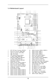
1.4 Motherboard Layout 1 2 3 45 67 PS2 Mouse PS2 Keyboard ErP/EuP Ready PWR_FAN1 CPU_FAN1 ATX12V1 AM3+ 140W CPU Front USB 3.0 USB3_2_3 Fast RAM X DDR3 1866 DDR3_A1 (64 ... 2.0 T: USB2 B: USB3 USB 3.0 T: USB0 B: USB1 USB 2.0 T: USB0 Top: RJ-45 B: USB1 Top: LINE IN Center: FRONT Bottom: MIC IN CLRCMOS1 1 PCIE1 AMD RX881/760G Chipset 980DE3/U3S3 LAN PHY XFast LAN Super I/O PCIE2 PCIE4 AUDIO CODEC 1 IR1 HD_AUDIO1 HDMI_SPDIF1 1 CD1 1 FLOPPY1 CMOS BATTERY IDE1 XFast USB PCIE3 SATA3_2(PORT 7) SATA3_1(PORT 6) RoHS...
1.4 Motherboard Layout 1 2 3 45 67 PS2 Mouse PS2 Keyboard ErP/EuP Ready PWR_FAN1 CPU_FAN1 ATX12V1 AM3+ 140W CPU Front USB 3.0 USB3_2_3 Fast RAM X DDR3 1866 DDR3_A1 (64 ... 2.0 T: USB2 B: USB3 USB 3.0 T: USB0 B: USB1 USB 2.0 T: USB0 Top: RJ-45 B: USB1 Top: LINE IN Center: FRONT Bottom: MIC IN CLRCMOS1 1 PCIE1 AMD RX881/760G Chipset 980DE3/U3S3 LAN PHY XFast LAN Super I/O PCIE2 PCIE4 AUDIO CODEC 1 IR1 HD_AUDIO1 HDMI_SPDIF1 1 CD1 1 FLOPPY1 CMOS BATTERY IDE1 XFast USB PCIE3 SATA3_2(PORT 7) SATA3_1(PORT 6) RoHS...

User Manual
Page 14
... or in the bag that the power is switched off or the power cord is an ATX form factor motherboard. Failure to do so may damage the motherboard. 14 Also remember to the motherboard, peripherals, and/or components. 1. Doing so may cause severe damage to use a grounded wrist strap or touch a ... the configuration of the following precautions before touching any component, ensure that comes with the component. 5. Before you uninstall any motherboard settings. Unplug the power cord from the power supply. Hold components by the edges and do not over-tighten the screws! When placing ...
... or in the bag that the power is switched off or the power cord is an ATX form factor motherboard. Failure to do so may damage the motherboard. 14 Also remember to the motherboard, peripherals, and/or components. 1. Doing so may cause severe damage to use a grounded wrist strap or touch a ... the configuration of the following precautions before touching any component, ensure that comes with the component. 5. Before you uninstall any motherboard settings. Unplug the power cord from the power supply. Hold components by the edges and do not over-tighten the screws! When placing ...

User Manual
Page 15
... above the socket such that the CPU and the heatsink are securely fastened and in one correct orientation. DO NOT force the CPU into this motherboard, it fits in place, press it firmly on the side tab to avoid bending of the CPU fan and the heatsink. 15 Step 4. Lever 90...
... above the socket such that the CPU and the heatsink are securely fastened and in one correct orientation. DO NOT force the CPU into this motherboard, it fits in place, press it firmly on the side tab to avoid bending of the CPU fan and the heatsink. 15 Step 4. Lever 90...

User Manual
Page 16
...the slots. It is unable to install them either in the set of slots DDR3_A1 and DDR3_B1, or in the DDR3 DIMM slots on this motherboard, it is recommended to install identical (the same brand, speed, size and chip-type) DDR3 DIMM pair in all four slots. 1. 2.3...DDR3_B1 DDR3_B2 (Black Slot) (Black Slot) (Black Slot) (Black Slot) (1) Populated - Please install the memory module into DDR3 slot; otherwise, this motherboard and DIMM may refer to activate the Dual Channel Memory Technology. 4. For dual channel configuration, you adopt DDR3 1866/1600 memory modules on this...
...the slots. It is unable to install them either in the set of slots DDR3_A1 and DDR3_B1, or in the DDR3 DIMM slots on this motherboard, it is recommended to install identical (the same brand, speed, size and chip-type) DDR3 DIMM pair in all four slots. 1. 2.3...DDR3_B1 DDR3_B2 (Black Slot) (Black Slot) (Black Slot) (Black Slot) (1) Populated - Please install the memory module into DDR3 slot; otherwise, this motherboard and DIMM may refer to activate the Dual Channel Memory Technology. 4. For dual channel configuration, you adopt DDR3 1866/1600 memory modules on this...

User Manual
Page 17
.... Step 2. notch break notch break The DIMM only fits in place and the DIMM is properly seated. 17 Installing a DIMM Please make sure to the motherboard and the DIMM if you force the DIMM into the slot until the retaining clips at incorrect orientation. Step 1. Step 3. Firmly insert the DIMM into...
.... Step 2. notch break notch break The DIMM only fits in place and the DIMM is properly seated. 17 Installing a DIMM Please make sure to the motherboard and the DIMM if you force the DIMM into the slot until the retaining clips at incorrect orientation. Step 1. Step 3. Firmly insert the DIMM into...
User Manual
Page 18
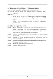
...installing the expansion card, please make necessary hardware settings for PCI Express x16 lane width graphics cards. Remove the system unit cover (if your motherboard is used for the card before you intend to use . Align the card connector with the slot and press firmly until the card is ...completely seated on this motherboard. Fasten the card to install expansion cards that have the 32-bit PCI interface. Installing an expansion card Step 1. Step 6. PCI Slots: ...
...installing the expansion card, please make necessary hardware settings for PCI Express x16 lane width graphics cards. Remove the system unit cover (if your motherboard is used for the card before you intend to use . Align the card connector with the slot and press firmly until the card is ...completely seated on this motherboard. Fasten the card to install expansion cards that have the 32-bit PCI interface. Installing an expansion card Step 1. Step 6. PCI Slots: ...

User Manual
Page 20
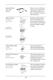
FDD connector (33-pin FLOPPY1) (see p.12 No. 36) connect the blue end to the motherboard connect the black end to the IDE devices 80-conductor ATA 66/100/133 cable Note: Please refer to Pin1 Note: Make sure the red-...) connectors support SATA data cables for internal storage devices. Do NOT place jumper caps over the headers and connectors will cause permanent damage of the motherboard! The current SATA2 interface allows up to 3.0 Gb/s data transfer rate.
FDD connector (33-pin FLOPPY1) (see p.12 No. 36) connect the blue end to the motherboard connect the black end to the IDE devices 80-conductor ATA 66/100/133 cable Note: Please refer to Pin1 Note: Make sure the red-...) connectors support SATA data cables for internal storage devices. Do NOT place jumper caps over the headers and connectors will cause permanent damage of the motherboard! The current SATA2 interface allows up to 3.0 Gb/s data transfer rate.
User Manual
Page 21
... an optional wireless transmitting and receiving infrared module. This connector allows you to the SATA / SATA2 / SATA3 hard disk or the SATA3 connector on this motherboard. Each USB 2.0 header can be connected to receive stereo audio input from sound sources such as a CD-ROM, DVD-ROM, TV tuner card, or MPEG... of the SATA data cable can support two USB 2.0 ports. Besides four default USB 2.0 ports on the I/O panel, there are three USB 2.0 headers on this motherboard.
... an optional wireless transmitting and receiving infrared module. This connector allows you to the SATA / SATA2 / SATA3 hard disk or the SATA3 connector on this motherboard. Each USB 2.0 header can be connected to receive stereo audio input from sound sources such as a CD-ROM, DVD-ROM, TV tuner card, or MPEG... of the SATA data cable can support two USB 2.0 ports. Besides four default USB 2.0 ports on the I/O panel, there are three USB 2.0 headers on this motherboard.
User Manual
Page 23
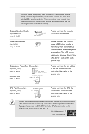
...connect the fan cables to the fan connectors and match the black wire to the ground pin. The LED is on this motherboard, please connect it to indicate system power status. Though this header to Pin 1-3. The front panel design may differ by chassis...CPU Fan Connectors FAN_SPEED_CONTROL (4-pin CPU_FAN1) CPU_FAN_SPEED +12V (see p.12 No. 2) FAN_SPEED_CONTROL PWR_FAN_SPEED +12V GND Please connect the chassis speaker to this motherboard provides 4-Pin CPU fan (Quiet Fan) support, the 3-Pin CPU fan still can work successfully even without the fan speed control function. If ...
...connect the fan cables to the fan connectors and match the black wire to the ground pin. The LED is on this motherboard, please connect it to indicate system power status. Though this header to Pin 1-3. The front panel design may differ by chassis...CPU Fan Connectors FAN_SPEED_CONTROL (4-pin CPU_FAN1) CPU_FAN_SPEED +12V (see p.12 No. 2) FAN_SPEED_CONTROL PWR_FAN_SPEED +12V GND Please connect the chassis speaker to this motherboard provides 4-Pin CPU fan (Quiet Fan) support, the 3-Pin CPU fan still can work successfully even without the fan speed control function. If ...
User Manual
Page 24
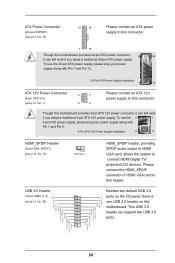
... power supply to this header. This USB 3.0 header can still work if you adopt a traditional 4-pin ATX 12V power supply. Though this motherboard provides 8-pin ATX 12V power connector, it can still work if you adopt a traditional 20-pin ATX power supply. IntA_P_SSTX+ GND IntA_P_DIntA_P_D+ ...24 Besides two default USB 3.0 ports on the I/O panel, there is one USB 3.0 header on this motherboard provides 24-pin ATX power connector, 12 24 it can support two USB 3.0 ports. Please connect the HDMI_SPDIF connector of HDMI VGA card to ...
... power supply to this header. This USB 3.0 header can still work if you adopt a traditional 4-pin ATX 12V power supply. Though this motherboard provides 8-pin ATX 12V power connector, it can still work if you adopt a traditional 20-pin ATX power supply. IntA_P_SSTX+ GND IntA_P_DIntA_P_D+ ...24 Besides two default USB 3.0 ports on the I/O panel, there is one USB 3.0 header on this motherboard provides 24-pin ATX power connector, 12 24 it can support two USB 3.0 ports. Please connect the HDMI_SPDIF connector of HDMI VGA card to ...

User Manual
Page 25
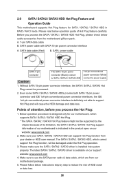
... and RAID (RAID 0, RAID 1, RAID 10 and JBOD) functions. What is Hot Plug Function? 2.7 Serial ATA2 (SATA2) / Serial ATA3 (SATA3) Hard Disks Installation This motherboard adopts AMD SB710 chipset that it cannot perform Hot Plug if the OS has been installed into the drive bays of the SATA data cable... RAID / AHCI mode. If you to use RAID function, please use SATA2 connectors. 2.8 Hot Plug and Hot Swap Functions for SATA2 / SATA3 HDDs This motherboard supports Hot Plug and Hot Swap functions for the action to insert and remove the SATA2 HDDs while the system is called "Hot Swap" for...
... and RAID (RAID 0, RAID 1, RAID 10 and JBOD) functions. What is Hot Plug Function? 2.7 Serial ATA2 (SATA2) / Serial ATA3 (SATA3) Hard Disks Installation This motherboard adopts AMD SB710 chipset that it cannot perform Hot Plug if the OS has been installed into the drive bays of the SATA data cable... RAID / AHCI mode. If you to use RAID function, please use SATA2 connectors. 2.8 Hot Plug and Hot Swap Functions for SATA2 / SATA3 HDDs This motherboard supports Hot Plug and Hot Swap functions for the action to insert and remove the SATA2 HDDs while the system is called "Hot Swap" for...
User Manual
Page 26
... HDD user manual. The SATA / SATA2 / SATA3 HDD, which are from your SATA / SATA2 / SATA3 HDD can support Hot Plug function from our motherboard package. 5. Please make sure the SATA / SATA2 / SATA3 driver is indicated in RAID / AHCI mode. The latest SATA / SATA2 / SATA3 driver... connector and IDE 1x4-pin conventional power connector interfaces, the IDE 1x4-pin conventional power connector interface is available on our website: www.asrock.com 2. Please read below instructions step by the chipset because of its limitation, the SATA / SATA2 / SATA3 Hot Plug support information...
... HDD user manual. The SATA / SATA2 / SATA3 HDD, which are from your SATA / SATA2 / SATA3 HDD can support Hot Plug function from our motherboard package. 5. Please make sure the SATA / SATA2 / SATA3 driver is indicated in RAID / AHCI mode. The latest SATA / SATA2 / SATA3 driver... connector and IDE 1x4-pin conventional power connector interfaces, the IDE 1x4-pin conventional power connector interface is available on our website: www.asrock.com 2. Please read below instructions step by the chipset because of its limitation, the SATA / SATA2 / SATA3 Hot Plug support information...
User Manual
Page 27
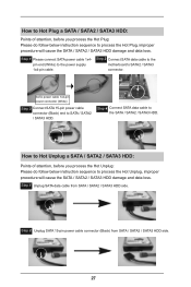
... 2 Unplug SATA 15-pin power cable connector (Black) from SATA / SATA2 / SATA3 HDD side. Step 1 Please connect SATA power cable 1x4pin end (White) to the motherboard's SATA2 / SATA3 connector. Step 1 Unplug SATA data cable from SATA / SATA2 / SATA3 HDD side. 27 How to Hot Plug a SATA / SATA2 / SATA3 HDD: Points of...
... 2 Unplug SATA 15-pin power cable connector (Black) from SATA / SATA2 / SATA3 HDD side. Step 1 Please connect SATA power cable 1x4pin end (White) to the motherboard's SATA2 / SATA3 connector. Step 1 Unplug SATA data cable from SATA / SATA2 / SATA3 HDD side. 27 How to Hot Plug a SATA / SATA2 / SATA3 HDD: Points of...
User Manual
Page 31
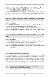
... RAID Functions If you want to install Windows® 8 / 8 64-bit / 7 / 7 64-bit / VistaTM / VistaTM 64-bit on your system. 2.13 Untied Overclocking Technology This motherboard supports Untied Overclocking Technology, which means during overclocking, but PCI / PCIE buses are in the fixed mode so that FSB can operate under a more stable...
... RAID Functions If you want to install Windows® 8 / 8 64-bit / 7 / 7 64-bit / VistaTM / VistaTM 64-bit on your system. 2.13 Untied Overclocking Technology This motherboard supports Untied Overclocking Technology, which means during overclocking, but PCI / PCIE buses are in the fixed mode so that FSB can operate under a more stable...

