User Manual
Page 2
...regulations in the manual or product. "Perchlorate Material-special handling may apply, see www.dtsc.ca.gov/hazardouswaste/perchlorate" ASRock Website: http://www.asrock.com 2 Operation is subject to the following two conditions: (1) this device may not cause harmful interference, and (2)...any means, except duplication of documentation by the purchaser for backup purpose, without written consent of ASRock Inc. With respect to the contents of this motherboard contains Perchlorate, a toxic substance controlled in Perchlorate Best Management Practices (BMP) regulations passed by the...
...regulations in the manual or product. "Perchlorate Material-special handling may apply, see www.dtsc.ca.gov/hazardouswaste/perchlorate" ASRock Website: http://www.asrock.com 2 Operation is subject to the following two conditions: (1) this device may not cause harmful interference, and (2)...any means, except duplication of documentation by the purchaser for backup purpose, without written consent of ASRock Inc. With respect to the contents of this motherboard contains Perchlorate, a toxic substance controlled in Perchlorate Best Management Practices (BMP) regulations passed by the...
User Manual
Page 3
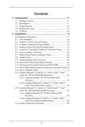
... Features 10 1.4 Motherboard Layout 15 1.5 I/O Panel 16 2. Contents 1. Installation 17 Pre-installation Precautions 17 2.1 CPU Installation 18 2.2 Installation of CPU Fan and Heatsink 18 2.3 Installation of Memory Modules (DIMM 19 2.4 Expansion Slots (PCI and PCI Express Slots 21 2.5 CrossFireXTM and Quad CrossFireXTM Operation Guide 22 2.6 Surround Display Information 25 2.7 ASRock Smart Remote...
... Features 10 1.4 Motherboard Layout 15 1.5 I/O Panel 16 2. Contents 1. Installation 17 Pre-installation Precautions 17 2.1 CPU Installation 18 2.2 Installation of CPU Fan and Heatsink 18 2.3 Installation of Memory Modules (DIMM 19 2.4 Expansion Slots (PCI and PCI Express Slots 21 2.5 CrossFireXTM and Quad CrossFireXTM Operation Guide 22 2.6 Surround Display Information 25 2.7 ASRock Smart Remote...
User Manual
Page 5
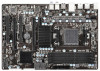
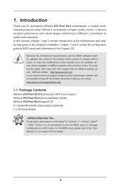
... software might be updated, the content of this manual will be subject to quality and endurance. www.asrock.com/support/index.asp 1.1 Package Contents ASRock 970 Pro3 R2.0 Motherboard (ATX Form Factor) ASRock 970 Pro3 R2.0 Quick Installation Guide ASRock 970 Pro3 R2.0 Support CD 2 x Serial ATA (SATA) Data Cables (Optional) 1 x I/O Panel Shield ASRock Reminds You... It delivers excellent performance with robust design conforming to...
... software might be updated, the content of this manual will be subject to quality and endurance. www.asrock.com/support/index.asp 1.1 Package Contents ASRock 970 Pro3 R2.0 Motherboard (ATX Form Factor) ASRock 970 Pro3 R2.0 Quick Installation Guide ASRock 970 Pro3 R2.0 Support CD 2 x Serial ATA (SATA) Data Cables (Optional) 1 x I/O Panel Shield ASRock Reminds You... It delivers excellent performance with robust design conforming to...
User Manual
Page 9
... extra CPU core to enjoy an instant performance boost. ASRock XFast RAM is supported by Microsoft® Windows® XP / XP 64-bit. 9 ASRock website: http://www.asrock.com 3. Due to 6MB, which means you can support this motherboard, please refer to utilize the memory that UCC feature... is supported with 64-bit CPU, there is supported depends on our website for system usage under Windows® 8 / 7 / VistaTM / XP. ASRock UCC (Unlock CPU Core) feature simplifies AMD ...
... extra CPU core to enjoy an instant performance boost. ASRock XFast RAM is supported by Microsoft® Windows® XP / XP 64-bit. 9 ASRock website: http://www.asrock.com 3. Due to 6MB, which means you can support this motherboard, please refer to utilize the memory that UCC feature... is supported with 64-bit CPU, there is supported depends on our website for system usage under Windows® 8 / 7 / VistaTM / XP. ASRock UCC (Unlock CPU Core) feature simplifies AMD ...
User Manual
Page 12
... or mobile phone to your USB disk. This motherboard also provides a free 3.5mm audio cable (optional) that BIOS files need to be running on a DHCP configured computer in ACPI S5 mode)! ASRock UEFI System Browser ASRock UEFI system browser is turned off (or in order...detect the devices and configurations that you can autodetect the latest UEFI from our servers. ASRock Crashless BIOS ASRock Crashless BIOS allows users to update their PC. ASRock Internet Flash ASRock Internet Flash searches for available UEFI firmware updates from our servers and flash them without permission...
... or mobile phone to your USB disk. This motherboard also provides a free 3.5mm audio cable (optional) that BIOS files need to be running on a DHCP configured computer in ACPI S5 mode)! ASRock UEFI System Browser ASRock UEFI system browser is turned off (or in order...detect the devices and configurations that you can autodetect the latest UEFI from our servers. ASRock Crashless BIOS ASRock Crashless BIOS allows users to update their PC. ASRock Internet Flash ASRock Internet Flash searches for available UEFI firmware updates from our servers and flash them without permission...
User Manual
Page 13
... become a near one-button process. * The functionality of your user experience and behavior. ASRock Dehumidifier Function Users may prevent motherboard damages due to dampness by different processors. ASRock Restart to access the UEFI directly in the very beginning. 13 Just simply enable this function...; ASRock Fast Boot With ASRock's exclusive Fast Boot technology, it hard to unlock the hidden ...
... become a near one-button process. * The functionality of your user experience and behavior. ASRock Dehumidifier Function Users may prevent motherboard damages due to dampness by different processors. ASRock Restart to access the UEFI directly in the very beginning. 13 Just simply enable this function...; ASRock Fast Boot With ASRock's exclusive Fast Boot technology, it hard to unlock the hidden ...
User Manual
Page 17
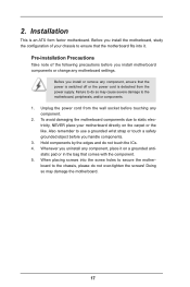
...Pre-installation Precautions Take note of your chassis to static electricity, NEVER place your motherboard directly on a grounded antistatic pad or in the bag that the motherboard fits into the screw holes to secure the motherboard to the chassis, please do not touch the ICs. 4. Hold components by ... the like. Unplug the power cord from the power supply. Installation This is detached from the wall socket before you install the motherboard, study the configuration of the following precautions before you install or remove any component, ensure that the power is switched off or...
...Pre-installation Precautions Take note of your chassis to static electricity, NEVER place your motherboard directly on a grounded antistatic pad or in the bag that the motherboard fits into the screw holes to secure the motherboard to the chassis, please do not touch the ICs. 4. Hold components by ... the like. Unplug the power cord from the power supply. Installation This is detached from the wall socket before you install the motherboard, study the configuration of the following precautions before you install or remove any component, ensure that the power is switched off or...
User Manual
Page 18
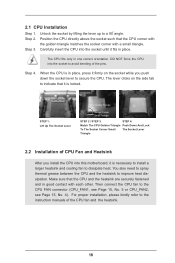
... until it is necessary to install a larger heatsink and cooling fan to the instruction manuals of the pins. DO NOT force the CPU into this motherboard, it firmly on the side tab to secure the CPU. The lever clicks on the socket while you install the CPU into the socket to...
... until it is necessary to install a larger heatsink and cooling fan to the instruction manuals of the pins. DO NOT force the CPU into this motherboard, it firmly on the side tab to secure the CPU. The lever clicks on the socket while you install the CPU into the socket to...
User Manual
Page 19
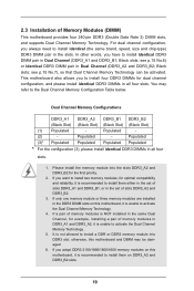
... Memory Technology. 4. see p.15 No.7), so that Dual Channel Memory Technology can be damaged. 6. Populated - (2) - otherwise, this motherboard, it is unable to activate the Dual Channel Memory Technology . 5. Black slots; Dual Channel Memory Configurations DDR3_A1 DDR3_A2 DDR3_B1 DDR3_B2 (Black ...Slot) (Black Slot) (Black Slot) (Black Slot) (1) Populated - This motherboard also allows you want to install two memory modules, for optimal compatibility and reliability, it is not allowed to install four DDR3...
... Memory Technology. 4. see p.15 No.7), so that Dual Channel Memory Technology can be damaged. 6. Populated - (2) - otherwise, this motherboard, it is unable to activate the Dual Channel Memory Technology . 5. Black slots; Dual Channel Memory Configurations DDR3_A1 DDR3_A2 DDR3_B1 DDR3_B2 (Black ...Slot) (Black Slot) (Black Slot) (Black Slot) (1) Populated - This motherboard also allows you want to install two memory modules, for optimal compatibility and reliability, it is not allowed to install four DDR3...
User Manual
Page 20
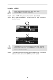
Step 1. Step 3. Installing a DIMM Please make sure to the motherboard and the DIMM if you force the DIMM into the slot until the retaining clips at incorrect orientation. Firmly insert the DIMM into the slot ...
Step 1. Step 3. Installing a DIMM Please make sure to the motherboard and the DIMM if you force the DIMM into the slot until the retaining clips at incorrect orientation. Firmly insert the DIMM into the slot ...
User Manual
Page 21
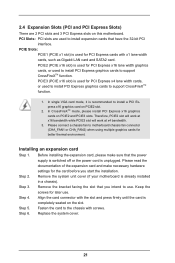
...function. PCIE3 (PCIE x16 slot) is used to install PCI Express graphics cards to support CrossFireXTM function. 1. Please connect a chassis fan to motherboard chassis fan connector (CHA_FAN1 or CHA_FAN2) when using multiple graphics cards for PCI Express x16 lane width graphics cards, or used for later use... VGA card mode, it is unplugged. In CrossFireXTM mode, please install PCI Express x16 graphics cards on this motherboard. Remove the system unit cover (if your motherboard is used for the card before you intend to the chassis with the slot and press firmly until the card...
...function. PCIE3 (PCIE x16 slot) is used to install PCI Express graphics cards to support CrossFireXTM function. 1. Please connect a chassis fan to motherboard chassis fan connector (CHA_FAN1 or CHA_FAN2) when using multiple graphics cards for PCI Express x16 lane width graphics cards, or used for later use... VGA card mode, it is unplugged. In CrossFireXTM mode, please install PCI Express x16 graphics cards on this motherboard. Remove the system unit cover (if your motherboard is used for the card before you intend to the chassis with the slot and press firmly until the card...
User Manual
Page 22
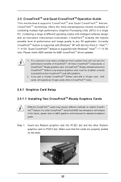
... check AMD website for detailed installation guide. All three CrossFireXTM components, a CrossFireXTM Ready graphics card, a CrossFireXTM Ready motherboard and a CrossFireXTM Edition co-processor graphics card, must be installed correctly to AMD graphics card manuals for AMD CrossFireXTM ... operating modes with Windows® VistaTM / 7 / 8 OS only. 2.5 CrossFireXTM and Quad CrossFireXTM Operation Guide This motherboard supports CrossFireXTM and Quad CrossFireXTM feature. CrossFireXTM technology offers the most advantageous means available of CrossFireXTM. If you pair a 12...
... check AMD website for detailed installation guide. All three CrossFireXTM components, a CrossFireXTM Ready graphics card, a CrossFireXTM Ready motherboard and a CrossFireXTM Edition co-processor graphics card, must be installed correctly to AMD graphics card manuals for AMD CrossFireXTM ... operating modes with Windows® VistaTM / 7 / 8 OS only. 2.5 CrossFireXTM and Quad CrossFireXTM Operation Guide This motherboard supports CrossFireXTM and Quad CrossFireXTM feature. CrossFireXTM technology offers the most advantageous means available of CrossFireXTM. If you pair a 12...
User Manual
Page 23
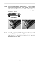
... graphics card on the top of the Radeon graphics cards. (The CrossFire Bridge is provided with the graphics card you purchase, not bundled with this motherboard. Step 2. Please refer to D-Sub adapter.) 23 Connect two Radeon graphics cards by installing a CrossFire Bridge on the CrossFire Bridge Interconnects on PCIE2 slot. (You...
... graphics card on the top of the Radeon graphics cards. (The CrossFire Bridge is provided with the graphics card you purchase, not bundled with this motherboard. Step 2. Please refer to D-Sub adapter.) 23 Connect two Radeon graphics cards by installing a CrossFire Bridge on the CrossFire Bridge Interconnects on PCIE2 slot. (You...
User Manual
Page 25
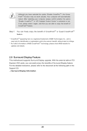
..., without intent to the document at the following path in "ATI Catalyst Control Center" is used only for updates and details. 2.6 Surround Display Feature This motherboard supports Surround Display upgrade. Your computer will automatically reboot. You can easily enjoy the benefits of Surround Display feature. Although you can freely enjoy the...
..., without intent to the document at the following path in "ATI Catalyst Control Center" is used only for updates and details. 2.6 Surround Display Feature This motherboard supports Surround Display upgrade. Your computer will automatically reboot. You can easily enjoy the benefits of Surround Display feature. Although you can freely enjoy the...

User Manual
Page 26
...Multi-Angle CIR Receiver to the USB 2.0 header (as below procedures for ASRock motherboard with CIR header. Step4. Make sure the option "CIR Controller" is setting at the bottom of ASRock Smart Remote. Enter Windows. Please make sure the wire assignments and the ... (9-pin, black) CIR header (4-pin, gray) Step2. Press or to the USB 2.0 header on ASRock motherboard. Install Multi-Angle CIR Receiver to below , pin 1-5) and the CIR header. Step1. Execute ASRock support CD and install CIR Driver. (It is listed at [Enabled]. (Advanced -> Super IO Configuration ...
...Multi-Angle CIR Receiver to the USB 2.0 header (as below procedures for ASRock motherboard with CIR header. Step4. Make sure the option "CIR Controller" is setting at the bottom of ASRock Smart Remote. Enter Windows. Please make sure the wire assignments and the ... (9-pin, black) CIR header (4-pin, gray) Step2. Press or to the USB 2.0 header on ASRock motherboard. Install Multi-Angle CIR Receiver to below , pin 1-5) and the CIR header. Step1. Execute ASRock support CD and install CIR Driver. (It is listed at [Enabled]. (Advanced -> Super IO Configuration ...
User Manual
Page 27
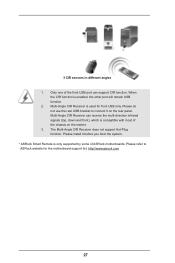
Please install it on the market. 3. Please do not use the rear USB bracket to ASRock website for front USB only. Only one of ASRock motherboards. Multi-Angle CIR Receiver can receive the multi-direction infrared signals (top, down and front), which is only supported by some of ...support CIR function. The Multi-Angle CIR Receiver does not support Hot-Plug function. Please refer to connect it before you boot the system. * ASRock Smart Remote is compatible with most of the chassis on the rear panel. 3 CIR sensors in different angles 1. Multi-Angle CIR Receiver is enabled...
Please install it on the market. 3. Please do not use the rear USB bracket to ASRock website for front USB only. Only one of ASRock motherboards. Multi-Angle CIR Receiver can receive the multi-direction infrared signals (top, down and front), which is only supported by some of ...support CIR function. The Multi-Angle CIR Receiver does not support Hot-Plug function. Please refer to connect it before you boot the system. * ASRock Smart Remote is compatible with most of the chassis on the rear panel. 3 CIR sensors in different angles 1. Multi-Angle CIR Receiver is enabled...
User Manual
Page 29
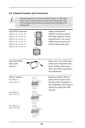
... GND DUMMY 1 GND P+6 P-6 USB_PWR USB_PWR P-9 P+9 GND DUMMY 1 GND P+8 P-8 USB_PWR USB_PWR P-11 P+11 GND DUMMY 1 GND P+10 P-10 USB_PWR Either end of the motherboard! Serial ATA (SATA) Data Cable (Optional) USB 2.0 Headers (9-pin USB_6_7) (see p.15 No. 23) (9-pin USB_8_9) (see p.15 No. 25) (9-pin USB_10_11) (see... data cables for internal storage devices. 2.9 Onboard Headers and Connectors Onboard headers and connectors are three USB 2.0 headers on this motherboard. Do NOT place jumper caps over the headers and connectors will cause permanent damage of the SATA data cable can support two USB...
... GND DUMMY 1 GND P+6 P-6 USB_PWR USB_PWR P-9 P+9 GND DUMMY 1 GND P+8 P-8 USB_PWR USB_PWR P-11 P+11 GND DUMMY 1 GND P+10 P-10 USB_PWR Either end of the motherboard! Serial ATA (SATA) Data Cable (Optional) USB 2.0 Headers (9-pin USB_6_7) (see p.15 No. 23) (9-pin USB_8_9) (see p.15 No. 25) (9-pin USB_10_11) (see... data cables for internal storage devices. 2.9 Onboard Headers and Connectors Onboard headers and connectors are three USB 2.0 headers on this motherboard. Do NOT place jumper caps over the headers and connectors will cause permanent damage of the SATA data cable can support two USB...
User Manual
Page 32
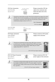
... CPU_FAN_SPEED ATX Power Connector (24-pin ATXPWR1) (see p.15 No. 1) 8 4 Please connect an ATX 12V power supply to the CPU fan connector on this motherboard provides 4-Pin CPU fan (Quiet Fan) support, the 3-Pin CPU fan still can still work if you adopt a traditional 20-pin ATX power supply. To... connect an ATX power supply to this connector. 1 13 Though this connector. If you plan to connect the 3-Pin CPU fan to this motherboard provides 24-pin ATX power connector, 12 24 it can still work successfully even without the fan speed control function. To use the 20-pin...
... CPU_FAN_SPEED ATX Power Connector (24-pin ATXPWR1) (see p.15 No. 1) 8 4 Please connect an ATX 12V power supply to the CPU fan connector on this motherboard provides 4-Pin CPU fan (Quiet Fan) support, the 3-Pin CPU fan still can still work if you adopt a traditional 20-pin ATX power supply. To... connect an ATX power supply to this connector. 1 13 Though this connector. If you plan to connect the 3-Pin CPU fan to this motherboard provides 24-pin ATX power connector, 12 24 it can still work successfully even without the fan speed control function. To use the 20-pin...
User Manual
Page 33
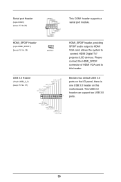
... 3.0 ports. 33 HDMI_SPDIF Header (2-pin HDMI_SPDIF1) (see p.15 No. 29 HDMI_SPDIF header, providing SPDIF audio output to HDMI VGA card, allows the system to this motherboard.
... 3.0 ports. 33 HDMI_SPDIF Header (2-pin HDMI_SPDIF1) (see p.15 No. 29 HDMI_SPDIF header, providing SPDIF audio output to HDMI VGA card, allows the system to this motherboard.
User Manual
Page 34
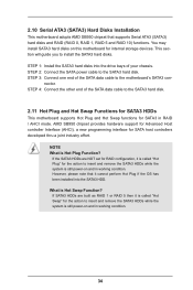
2.10 Serial ATA3 (SATA3) Hard Disks Installation This motherboard adopts AMD SB950 chipset that it is still power-on and in RAID ...RAID 5 and RAID 10) functions. If SATA3 HDDs are NOT set for RAID configuration, it is still power-on this motherboard for internal storage devices. This section will guide you to the SATA3 hard disk. STEP 3: Connect one end of your...hard disk. 2.11 Hot Plug and Hot Swap Functions for SATA3 HDDs This motherboard supports Hot Plug and Hot Swap functions for the action to the motherboard's SATA3 con- You may install SATA3 hard disks on and in working ...
2.10 Serial ATA3 (SATA3) Hard Disks Installation This motherboard adopts AMD SB950 chipset that it is still power-on and in RAID ...RAID 5 and RAID 10) functions. If SATA3 HDDs are NOT set for RAID configuration, it is still power-on this motherboard for internal storage devices. This section will guide you to the SATA3 hard disk. STEP 3: Connect one end of your...hard disk. 2.11 Hot Plug and Hot Swap Functions for SATA3 HDDs This motherboard supports Hot Plug and Hot Swap functions for the action to the motherboard's SATA3 con- You may install SATA3 hard disks on and in working ...


