RAID Installation Guide
Page 1
AMD BIOS RAID Installation Guide 2 1.1 Introduction to RAIDXpert from the Internet 18 2.9 Running RAIDXpert without Network Connection 18 1 AMD Windows RAID Installation Guide 11 2.1 Components of RAIDXpert ...
AMD BIOS RAID Installation Guide 2 1.1 Introduction to RAIDXpert from the Internet 18 2.9 Running RAIDXpert without Network Connection 18 1 AMD Windows RAID Installation Guide 11 2.1 Components of RAIDXpert ...
RAID Installation Guide
Page 2
...all applications to read and write data in our support CD or "Quick Installation Guide", then you make a SATA3 driver diskette, press or to enter BIOS setup to set . RAID 0 (Data Striping) RAID 0 is called data mirroring that optimizes two identical hard disk drives to the surviving drive as fault... disks perform the same work as a single drive but at a sustained data transfer rate. After you can be mirrored using the onboard FastBuild BIOS utility under BIOS environment. AMD BIOS RAID Installation Guide AMD BIOS RAID Installation Guide is the most versatile RAID Level.
...all applications to read and write data in our support CD or "Quick Installation Guide", then you make a SATA3 driver diskette, press or to enter BIOS setup to set . RAID 0 (Data Striping) RAID 0 is called data mirroring that optimizes two identical hard disk drives to the surviving drive as fault... disks perform the same work as a single drive but at a sustained data transfer rate. After you can be mirrored using the onboard FastBuild BIOS utility under BIOS environment. AMD BIOS RAID Installation Guide AMD BIOS RAID Installation Guide is the most versatile RAID Level.

RAID Installation Guide
Page 4
Insert the ASRock Support CD into the floppy drive. Please refer to install a third-party RAID driver. At the beginning of 2 or more SATA3 HDDs with RAID functions, ... drive to boot your system. Formatting the floppy diskette will see the message on a RAID disk composed of Windows® setup, press F6 to the BIOS RAID installation guide part in it! E. Set the "SATA Mode" option to format and copy files [YN]? During POST at the beginning of system boot...
Insert the ASRock Support CD into the floppy drive. Please refer to install a third-party RAID driver. At the beginning of 2 or more SATA3 HDDs with RAID functions, ... drive to boot your system. Formatting the floppy diskette will see the message on a RAID disk composed of Windows® setup, press F6 to the BIOS RAID installation guide part in it! E. Set the "SATA Mode" option to format and copy files [YN]? During POST at the beginning of system boot...

RAID Installation Guide
Page 5
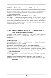
B. STEP 3: Make a SATA3 Driver Diskette. (Please use USB floppy or floppy disk.) Make a SATA3 driver diskette by following section 1.3.1 step 2 on your system. 5 STEP 2: Use "RAID Installation Guide" to [RAID]. STEP 4: Install Windows® 7 / 7 64-bit / VistaTM / VistaTM 64-bit OS on page 4. Before you start to configure RAID function, you need to the BIOS RAID installation guide part in this RAID installation guide for details. Please refer to check this document for proper configuration. Set the "SATA Mode" option to set RAID configuration.
B. STEP 3: Make a SATA3 Driver Diskette. (Please use USB floppy or floppy disk.) Make a SATA3 driver diskette by following section 1.3.1 step 2 on your system. 5 STEP 2: Use "RAID Installation Guide" to [RAID]. STEP 4: Install Windows® 7 / 7 64-bit / VistaTM / VistaTM 64-bit OS on page 4. Before you start to configure RAID function, you need to the BIOS RAID installation guide part in this RAID installation guide for details. Please refer to check this document for proper configuration. Set the "SATA Mode" option to set RAID configuration.

User Manual
Page 5
... of the Support CD. Chapter 3 and 4 contain the configuration guide to BIOS setup and information of the motherboard and stepby-step guide to change without further notice. www.asrock.com/support/index.asp 1.1 Package Contents ASRock 970 Extreme3 R2.0 Motherboard (ATX Form Factor) ASRock 970 Extreme3 R2.0 Quick Installation Guide ASRock 970 Extreme3 R2.0 Support CD 2 x Serial ATA (SATA) Data Cables (Optional) 1 x I/O Panel Shield...
... of the Support CD. Chapter 3 and 4 contain the configuration guide to BIOS setup and information of the motherboard and stepby-step guide to change without further notice. www.asrock.com/support/index.asp 1.1 Package Contents ASRock 970 Extreme3 R2.0 Motherboard (ATX Form Factor) ASRock 970 Extreme3 R2.0 Quick Installation Guide ASRock 970 Extreme3 R2.0 Support CD 2 x Serial ATA (SATA) Data Cables (Optional) 1 x I/O Panel Shield...
User Manual
Page 7
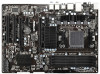
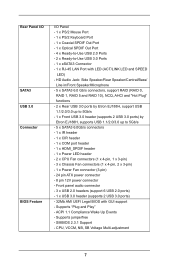
Rear Panel I/O SATA3 USB 3.0 Connector BIOS Feature I/O Panel - 1 x PS/2 Mouse Port - 1 x PS/2 Keyboard Port - 1 x Coaxial SPDIF Out Port - 1 x Optical SPDIF Out Port - 4 x Ready-to-Use USB 2.0 Ports - 2 x Ready-to 5Gb/s - 5 x... 1.1 Compliance Wake Up Events - SMBIOS 2.3.1 Support - Front panel audio connector - 3 x USB 2.0 headers (support 6 USB 2.0 ports) - 1 x USB 3.0 header (supports 2 USB 3.0 ports) - 32Mb AMI UEFI Legal BIOS with LED (ACT/LINK LED and SPEED LED) - HD Audio Jack: Side Speaker/Rear Speaker/Central/Bass/ Line in/Front Speaker/Microphone - 5 x SATA3 6.0 Gb/s connectors...
Rear Panel I/O SATA3 USB 3.0 Connector BIOS Feature I/O Panel - 1 x PS/2 Mouse Port - 1 x PS/2 Keyboard Port - 1 x Coaxial SPDIF Out Port - 1 x Optical SPDIF Out Port - 4 x Ready-to-Use USB 2.0 Ports - 2 x Ready-to 5Gb/s - 5 x... 1.1 Compliance Wake Up Events - SMBIOS 2.3.1 Support - Front panel audio connector - 3 x USB 2.0 headers (support 6 USB 2.0 ports) - 1 x USB 3.0 header (supports 2 USB 3.0 ports) - 32Mb AMI UEFI Legal BIOS with LED (ACT/LINK LED and SPEED LED) - HD Audio Jack: Side Speaker/Rear Speaker/Central/Bass/ Line in/Front Speaker/Microphone - 5 x SATA3 6.0 Gb/s connectors...

User Manual
Page 8
... system. CPU Temperature Sensing Monitor - ErP/EuP Ready (ErP/EuP ready power supply is required) * For detailed product information, please visit our website: http://www.asrock.com WARNING Please realize that there is a certain risk involved with overclocking, including adjusting the setting in the...
... system. CPU Temperature Sensing Monitor - ErP/EuP Ready (ErP/EuP ready power supply is required) * For detailed product information, please visit our website: http://www.asrock.com WARNING Please realize that there is a certain risk involved with overclocking, including adjusting the setting in the...

User Manual
Page 10
... S4 at specific timing during the POST or the key to enter into the BIOS setup menu to get the same OC settings. 1.3 Unique Features ASRock Extreme Tuning Utility (AXTU) ASRock Extreme Tuning Utility (AXTU) is a BIOS flash utility embedded in Flash ROM. In Overclocking, you are idle without entering ...174; to shorten boot up time. Just launch this utility, you can load the OC profile to their own system to access ASRock Instant Flash. This convenient BIOS update tool allows you can save energy, time, money, and improves system running speed for your friends. Please be used under ...
... S4 at specific timing during the POST or the key to enter into the BIOS setup menu to get the same OC settings. 1.3 Unique Features ASRock Extreme Tuning Utility (AXTU) ASRock Extreme Tuning Utility (AXTU) is a BIOS flash utility embedded in Flash ROM. In Overclocking, you are idle without entering ...174; to shorten boot up time. Just launch this utility, you can load the OC profile to their own system to access ASRock Instant Flash. This convenient BIOS update tool allows you can save energy, time, money, and improves system running speed for your friends. Please be used under ...

User Manual
Page 12
...to modify the system time are required. If power loss occurs during the BIOS update process, ASRock Crashless BIOS will automatically finish the BIOS update procedure after regaining power. ASRock On/Off Play Technology ASRock On/Off Play Technology allows users to enjoy the great audio experience from ...ports support this function. It can detect the devices and configurations that ensures users the most convenient computing environment. ASRock Crashless BIOS ASRock Crashless BIOS allows users to establish an internet curfew or restrict internet access at specified times via OMG.
...to modify the system time are required. If power loss occurs during the BIOS update process, ASRock Crashless BIOS will automatically finish the BIOS update procedure after regaining power. ASRock On/Off Play Technology ASRock On/Off Play Technology allows users to enjoy the great audio experience from ...ports support this function. It can detect the devices and configurations that ensures users the most convenient computing environment. ASRock Crashless BIOS ASRock Crashless BIOS allows users to establish an internet curfew or restrict internet access at specified times via OMG.
User Manual
Page 13
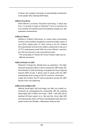
...Keyboard LED when the system enters into Standby / Hibernation mode as well. 13 ASRock X-Boost ASRock's X-Boost Technology is a smart auto-overclocking function and is brilliantly designed to access the UEFI directly in BIOS, the Power / HDD / LAN LED will automatically switch off when system ...is designed for those requiring frequent UEFI access. With the smart X-Boost, overclocking CPU can offer you a better environment by different processors. ASRock Restart to easily enter ...
...Keyboard LED when the system enters into Standby / Hibernation mode as well. 13 ASRock X-Boost ASRock's X-Boost Technology is a smart auto-overclocking function and is brilliantly designed to access the UEFI directly in BIOS, the Power / HDD / LAN LED will automatically switch off when system ...is designed for those requiring frequent UEFI access. With the smart X-Boost, overclocking CPU can offer you a better environment by different processors. ASRock Restart to easily enter ...

User Manual
Page 14
... RJ-45 LAN USB 2.0 T: USB2 B: USB3 eSATA3 USB 3.0 T: USB0 B: USB1 CHA_FAN3 SOCKET AM3b CPU_FAN2 CPU_FAN1 Front USB 3.0 USB3_2_3 AMD 970 PCIE1 Chipset PCIE2 AM3+ 140W CPU DDR3 2100+ Support 8-Core CPU DDR3_A1 (64 bit, 240-FpinSBmo8d0ul0e) DDR3_A2 (64 bit, 240-pin module...HD_AUDIO1 1 HDMI_SPDIF1 1 PCIE3 CMOS X Fast LAN BATTERY PCIE4 AMD SB950 Chipset 970 Extreme3 PCI1 ErP/EuP Ready COM1 1 PCI2 IR1 1 1 USB_8_9 RoHS USB_6_7 1 X Fast RAM X Fast USB SPEAKER1 1 PLED1 CLRCMOS1 1 1 32Mb BIOS SATA3_3 USB_4_5 1 1 CIR1 PANEL 1 PLED PWRBTN 1 HDLED RESET SATA3_5 ...
... RJ-45 LAN USB 2.0 T: USB2 B: USB3 eSATA3 USB 3.0 T: USB0 B: USB1 CHA_FAN3 SOCKET AM3b CPU_FAN2 CPU_FAN1 Front USB 3.0 USB3_2_3 AMD 970 PCIE1 Chipset PCIE2 AM3+ 140W CPU DDR3 2100+ Support 8-Core CPU DDR3_A1 (64 bit, 240-FpinSBmo8d0ul0e) DDR3_A2 (64 bit, 240-pin module...HD_AUDIO1 1 HDMI_SPDIF1 1 PCIE3 CMOS X Fast LAN BATTERY PCIE4 AMD SB950 Chipset 970 Extreme3 PCI1 ErP/EuP Ready COM1 1 PCI2 IR1 1 1 USB_8_9 RoHS USB_6_7 1 X Fast RAM X Fast USB SPEAKER1 1 PLED1 CLRCMOS1 1 1 32Mb BIOS SATA3_3 USB_4_5 1 1 CIR1 PANEL 1 PLED PWRBTN 1 HDLED RESET SATA3_5 ...

User Manual
Page 26
USB 2.0 header (9-pin, black) CIR header (4-pin, gray) Step2. Install Multi-Angle CIR Receiver to enter BIOS Setup Utility. Execute ASRock support CD and install CIR Driver. (It is listed at [Enabled]. (Advanced -> Super IO Configuration -> CIR Controller -> [Enabled]) If you cannot find ...assignments and the USB_PWR PP+ GND DUMMY pin assignments are matched correctly. 1 23 45 GND IRTX IRRX ATX+5VSB Step3. 2.7 ASRock Smart Remote Installation Guide ASRock Smart Remote is only used for the quick installation and usage of driver list.) 26 Find the CIR header located next to the...
USB 2.0 header (9-pin, black) CIR header (4-pin, gray) Step2. Install Multi-Angle CIR Receiver to enter BIOS Setup Utility. Execute ASRock support CD and install CIR Driver. (It is listed at [Enabled]. (Advanced -> Super IO Configuration -> CIR Controller -> [Enabled]) If you cannot find ...assignments and the USB_PWR PP+ GND DUMMY pin assignments are matched correctly. 1 23 45 GND IRTX IRRX ATX+5VSB Step3. 2.7 ASRock Smart Remote Installation Guide ASRock Smart Remote is only used for the quick installation and usage of driver list.) 26 Find the CIR header located next to the...

User Manual
Page 28
... is placed on pins, the jumper is "Open". After waiting for 5 seconds. If you need to clear the CMOS when you just finish updating the BIOS, you must boot up the system first, and then shut it down before you do not clear the CMOS right after you to clear the... cord from the power supply. Jumper Setting Description Clear CMOS Jumper (CLRCMOS1) (see p.14, No. 21) Default Clear CMOS Note: CLRCMOS1 allows you update the BIOS. 2.8 Jumpers Setup The illustration shows how jumpers are "Short" when jumper cap is placed on these 2 pins.
... is placed on pins, the jumper is "Open". After waiting for 5 seconds. If you need to clear the CMOS when you just finish updating the BIOS, you must boot up the system first, and then shut it down before you do not clear the CMOS right after you to clear the... cord from the power supply. Jumper Setting Description Clear CMOS Jumper (CLRCMOS1) (see p.14, No. 21) Default Clear CMOS Note: CLRCMOS1 allows you update the BIOS. 2.8 Jumpers Setup The illustration shows how jumpers are "Short" when jumper cap is placed on these 2 pins.
User Manual
Page 38
... 64-bit OS on your system. 38 Please refer to install a third-party RAID driver. Please refer to the BIOS RAID installation guide part of Windows® setup, press F6 to the BIOS RAID installation guide part of 2 or more SATA3 HDDs with RAID functions, please follow below steps. STEP 2: Use "RAID...
... 64-bit OS on your system. 38 Please refer to install a third-party RAID driver. Please refer to the BIOS RAID installation guide part of Windows® setup, press F6 to the BIOS RAID installation guide part of 2 or more SATA3 HDDs with RAID functions, please follow below steps. STEP 2: Use "RAID...
User Manual
Page 59
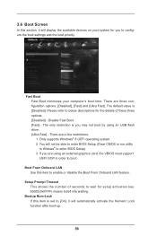
.... [Fast] - Only supports Windows® 8 UEFI operating system. 2. 3.6 Boot Screen In this section, it will not be able to enter BIOS Setup (Clear CMOS or run utility in order to enter BIOS Setup). 3. Fast Boot Fast Boot minimizes your system for you may not boot by using an external graphics card, the...
.... [Fast] - Only supports Windows® 8 UEFI operating system. 2. 3.6 Boot Screen In this section, it will not be able to enter BIOS Setup (Clear CMOS or run utility in order to enter BIOS Setup). 3. Fast Boot Fast Boot minimizes your system for you may not boot by using an external graphics card, the...
User Manual
Page 64
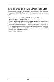
... drive.) You can also press to be installed on a large size HDD (>2TB). Installing OS on a HDD Larger Than 2TB This motherboard is adopting UEFI BIOS that allows Windows® OS to launch boot menu at system POST.
... drive.) You can also press to be installed on a large size HDD (>2TB). Installing OS on a HDD Larger Than 2TB This motherboard is adopting UEFI BIOS that allows Windows® OS to launch boot menu at system POST.
User Manual
Page 65
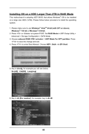
... make sure to be installed on a large size HDD (>2TB). Installing OS on a HDD Larger Than 2TB in RAID Mode This motherboard is adopting UEFI BIOS that allows Windows® OS to use Windows® VistaTM 64-bit (with SP1 or above), Windows® 7 64-bit or Windows® 8 64-bit...
... make sure to be installed on a large size HDD (>2TB). Installing OS on a HDD Larger Than 2TB in RAID Mode This motherboard is adopting UEFI BIOS that allows Windows® OS to use Windows® VistaTM 64-bit (with SP1 or above), Windows® 7 64-bit or Windows® 8 64-bit...

Quick Installation Guide
Page 2
...T: USB2 B: USB3 eSATA3 USB 3.0 T: USB0 B: USB1 CHA_FAN3 SOCKET AM3b CPU_FAN2 CPU_FAN1 Front USB 3.0 USB3_2_3 AMD 970 PCIE1 Chipset PCIE2 AM3+ 140W CPU DDR3 2100+ Support 8-Core CPU DDR3_A1 (64 bit, 240-FpinSBmo8d0ul0e) DDR3_A2 (64...CMOS X Fast LAN BATTERY PCIE4 AMD SB950 Chipset 970 Extreme3 PCI1 ErP/EuP Ready COM1 1 PCI2 IR1 1 1 USB_8_9 RoHS USB_6_7 1 X Fast RAM X Fast USB SPEAKER1 1 PLED1 CLRCMOS1 1 1 32Mb BIOS SATA3_3 USB_4_5 1 1 CIR1 PANEL 1 PLED ... Express 2.0 x1 Slot (PCIE1) 38 USB 3.0 Header (USB3_2_3) 2 ASRock 970 Extreme3 R2.0 Motherboard English
...T: USB2 B: USB3 eSATA3 USB 3.0 T: USB0 B: USB1 CHA_FAN3 SOCKET AM3b CPU_FAN2 CPU_FAN1 Front USB 3.0 USB3_2_3 AMD 970 PCIE1 Chipset PCIE2 AM3+ 140W CPU DDR3 2100+ Support 8-Core CPU DDR3_A1 (64 bit, 240-FpinSBmo8d0ul0e) DDR3_A2 (64...CMOS X Fast LAN BATTERY PCIE4 AMD SB950 Chipset 970 Extreme3 PCI1 ErP/EuP Ready COM1 1 PCI2 IR1 1 1 USB_8_9 RoHS USB_6_7 1 X Fast RAM X Fast USB SPEAKER1 1 PLED1 CLRCMOS1 1 1 32Mb BIOS SATA3_3 USB_4_5 1 1 CIR1 PANEL 1 PLED ... Express 2.0 x1 Slot (PCIE1) 38 USB 3.0 Header (USB3_2_3) 2 ASRock 970 Extreme3 R2.0 Motherboard English

Quick Installation Guide
Page 5
.../support/index.asp 1.1 Package Contents ASRock 970 Extreme3 R2.0 Motherboard (ATX Form Factor) ASRock 970 Extreme3 R2.0 Quick Installation Guide ASRock 970 Extreme3 R2.0 Support CD 2 x Serial ATA (SATA) Data Cables (Optional) 1 x I/O Panel Shield ASRock Reminds You... To get better performance in Windows® 8 / 8 64-bit / 7 / 7 64-bit / VistaTM / VistaTM 64-bit, it is recommended to set the BIOS option in the Support CD...
.../support/index.asp 1.1 Package Contents ASRock 970 Extreme3 R2.0 Motherboard (ATX Form Factor) ASRock 970 Extreme3 R2.0 Quick Installation Guide ASRock 970 Extreme3 R2.0 Support CD 2 x Serial ATA (SATA) Data Cables (Optional) 1 x I/O Panel Shield ASRock Reminds You... To get better performance in Windows® 8 / 8 64-bit / 7 / 7 64-bit / VistaTM / VistaTM 64-bit, it is recommended to set the BIOS option in the Support CD...
Quick Installation Guide
Page 7
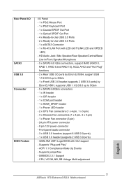
...- CPU, VCCM, NB, SB Voltage Multi-adjustment English 7 ASRock 970 Extreme3 R2.0 Motherboard Front panel audio connector - 3 x USB 2.0 headers (support 6 USB 2.0 ports) - 1 x USB 3.0 header (supports 2 USB 3.0 ports) - 32Mb AMI UEFI Legal BIOS with LED (ACT/LINK LED and SPEED LED) - Supports ...EJ188H, supports USB 1.1/2.0/3.0 up to -Use USB 3.0 Ports - 1 x eSATA3 Connector - 1 x RJ-45 LAN Port with GUI support - Rear Panel I/O SATA3 USB 3.0 Connector BIOS Feature I/O Panel - 1 x PS/2 Mouse Port - 1 x PS/2 Keyboard Port - 1 x Coaxial SPDIF Out Port - 1 x Optical SPDIF Out Port - 4 x ...
...- CPU, VCCM, NB, SB Voltage Multi-adjustment English 7 ASRock 970 Extreme3 R2.0 Motherboard Front panel audio connector - 3 x USB 2.0 headers (support 6 USB 2.0 ports) - 1 x USB 3.0 header (supports 2 USB 3.0 ports) - 32Mb AMI UEFI Legal BIOS with LED (ACT/LINK LED and SPEED LED) - Supports ...EJ188H, supports USB 1.1/2.0/3.0 up to -Use USB 3.0 Ports - 1 x eSATA3 Connector - 1 x RJ-45 LAN Port with GUI support - Rear Panel I/O SATA3 USB 3.0 Connector BIOS Feature I/O Panel - 1 x PS/2 Mouse Port - 1 x PS/2 Keyboard Port - 1 x Coaxial SPDIF Out Port - 1 x Optical SPDIF Out Port - 4 x ...


