User Manual
Page 3
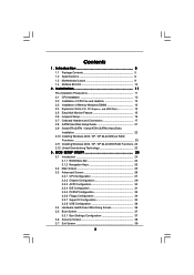
... 24 3.1.1 BIOS Menu Bar 24 3.1.2 Navigation Keys 25 3.2 Main Screen 25 3.3 Advanced Screen 26 3.3.1 CPU Configuration 27 3.3.2 Chipset Configuration 29 3.3.3 ACPI Configuration 30 3.3.4 IDE Configuration 31 3.3.5 PCIPnP Configuration 33 3.3.6 Floppy...Screen 39 3 Introduction 5 1.1 Package Contents 5 1.2 Specifications 6 1.3 Motherboard Layout 9 1.4 ASRock 8CH I/O 10 2 . Contents 1 . Installation 11 Pre-installation Precautions 11 2.1 CPU Installation 12 2.2 Installation of CPU Fan and Heatsink 12 2.3 Installation of Memory Modules (DIMM 13 2.4 Expansion Slots (PCI, PCI...
... 24 3.1.1 BIOS Menu Bar 24 3.1.2 Navigation Keys 25 3.2 Main Screen 25 3.3 Advanced Screen 26 3.3.1 CPU Configuration 27 3.3.2 Chipset Configuration 29 3.3.3 ACPI Configuration 30 3.3.4 IDE Configuration 31 3.3.5 PCIPnP Configuration 33 3.3.6 Floppy...Screen 39 3 Introduction 5 1.1 Package Contents 5 1.2 Specifications 6 1.3 Motherboard Layout 9 1.4 ASRock 8CH I/O 10 2 . Contents 1 . Installation 11 Pre-installation Precautions 11 2.1 CPU Installation 12 2.2 Installation of CPU Fan and Heatsink 12 2.3 Installation of Memory Modules (DIMM 13 2.4 Expansion Slots (PCI, PCI...

User Manual
Page 5
... latest memory and CPU support lists on ASRock website without notice. In case any modifications of this manual occur, the updated version will be available on ASRock website as well. Introduction Thank you for purchasing ASRock 939NF4G-SATA2 motherboard, a reliable motherboard produced under ASRock's consistently stringent quality control. ASRock website http://www.asrock.com 1.1 Package Contents 1 x ASRock 939NF4G-SATA2 Motherboard (Micro ATX...
... latest memory and CPU support lists on ASRock website without notice. In case any modifications of this manual occur, the updated version will be available on ASRock website as well. Introduction Thank you for purchasing ASRock 939NF4G-SATA2 motherboard, a reliable motherboard produced under ASRock's consistently stringent quality control. ASRock website http://www.asrock.com 1.1 Package Contents 1 x ASRock 939NF4G-SATA2 Motherboard (Micro ATX...

User Manual
Page 6
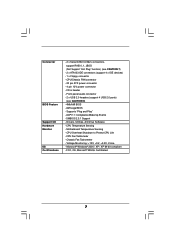
... - 1 x AMR slot - Realtek PHY RTL8201CL - Southbridge: nVidia® nForce 410 MCP - CPU Frequency Stepless Control (see CAUTION 2) - Pixel Shader 3.0 - Supports Wake-On-LAN ASRock 8CH I /O - FSB 1 GHz (2.0 GT/s) - Supports Untied Overclocking Technology (see CAUTION 4) - Northbridge: nVidia® GeForce 6100 - CPU Voltage - ASRock U-COP (see CAUTION 3) - 4 x DDR DIMM slots - Micro ATX Form Factor: 9.6-in x 8.8-in...
... - 1 x AMR slot - Realtek PHY RTL8201CL - Southbridge: nVidia® nForce 410 MCP - CPU Frequency Stepless Control (see CAUTION 2) - Pixel Shader 3.0 - Supports Wake-On-LAN ASRock 8CH I /O - FSB 1 GHz (2.0 GT/s) - Supports Untied Overclocking Technology (see CAUTION 4) - Northbridge: nVidia® GeForce 6100 - CPU Voltage - ASRock U-COP (see CAUTION 3) - 4 x DDR DIMM slots - Micro ATX Form Factor: 9.6-in x 8.8-in...
User Manual
Page 7
... - SMBIOS 2.3.1 Support - CPU Temperature Sensing - Chassis Fan Tachometer - ACPI 1.1 Compliance Wake Up Events - Microsoft® Windows® 2000 / XP / XP 64-bit compliant - Motherboard Temperature Sensing .../s connectors, support RAID 0, 1, JBOD (Not Support "Hot Plug" function) (see CAUTION 8) - 4Mb AMI BIOS - AMI Legal BIOS - Drivers, Utilities, AntiVirus Software - CPU Overheat Shutdown to Protect CPU Life - CPU/Chassis FAN connector - 20 pin ATX power connector - 4 pin 12V power connector - Front panel audio connector - 2 x USB 2.0 headers (support 4 USB 2.0 ports) (...
... - SMBIOS 2.3.1 Support - CPU Temperature Sensing - Chassis Fan Tachometer - ACPI 1.1 Compliance Wake Up Events - Microsoft® Windows® 2000 / XP / XP 64-bit compliant - Motherboard Temperature Sensing .../s connectors, support RAID 0, 1, JBOD (Not Support "Hot Plug" function) (see CAUTION 8) - 4Mb AMI BIOS - AMI Legal BIOS - Drivers, Utilities, AntiVirus Software - CPU Overheat Shutdown to Protect CPU Life - CPU/Chassis FAN connector - 20 pin ATX power connector - 4 pin 12V power connector - Front panel audio connector - 2 x USB 2.0 headers (support 4 USB 2.0 ports) (...
User Manual
Page 8
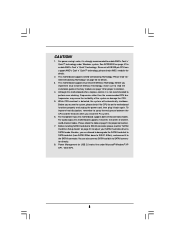
...connection. 7. For power-saving's sake, it is not recommended to read the installation guide of the system or damage the CPU. 5. Since not all K8 939-pin CPU can also connect SATA hard disk to the SATAII connector. Before you install the PC system. 6. Frequencies other than the ... unplug the power cord, then plug it to SATAII connector directly. 8. While CPU overheat is strongly recommended to spray thermal grease between the CPU and the heatsink when you resume the system, please check if the CPU fan on page 13 for details. 3. To improve heat dissipation, remember to...
...connection. 7. For power-saving's sake, it is not recommended to read the installation guide of the system or damage the CPU. 5. Since not all K8 939-pin CPU can also connect SATA hard disk to the SATAII connector. Before you install the PC system. 6. Frequencies other than the ... unplug the power cord, then plug it to SATAII connector directly. 8. While CPU overheat is strongly recommended to spray thermal grease between the CPU and the heatsink when you resume the system, please check if the CPU fan on page 13 for details. 3. To improve heat dissipation, remember to...

User Manual
Page 12
... is in place, press it fits in place. Then connect the CPU fan to a 90o angle. DO NOT force the CPU into this motherboard, it is locked. The CPU fits only in good contact with a small triangle. When the CPU is necessary to install a larger heatsink and cooling fan to avoid... bending of the pins. Step 4. Lever 90° Up CPU Golden Triangle STEP 1: Lift Up The Socket Lever Socket Corner STEP 2 / STEP 3: STEP 4: Match The CPU Golden Triangle Push Down And Lock To The Socket Corner The Socket Lever 2.2 Installation of the...
... is in place, press it fits in place. Then connect the CPU fan to a 90o angle. DO NOT force the CPU into this motherboard, it is locked. The CPU fits only in good contact with a small triangle. When the CPU is necessary to install a larger heatsink and cooling fan to avoid... bending of the pins. Step 4. Lever 90° Up CPU Golden Triangle STEP 1: Lift Up The Socket Lever Socket Corner STEP 2 / STEP 3: STEP 4: Match The CPU Golden Triangle Push Down And Lock To The Socket Corner The Socket Lever 2.2 Installation of the...

User Manual
Page 19
...pin PANEL1) (see p.9 No. 16) Chassis Speaker Header (4-pin SPEAKER 1) (see p.9 No. 14) Chassis Fan Connector (3-pin CHA_FAN1) (see p.9 No. 15) CPU Fan Connector (3-pin CPU_FAN1) (see p.9 No. 10) ATX Power Connector (20-pin ATXPWR1) (see p.9 item 32) +5V JBB1 JBX MIDI_OUT JBY JBB2 MIDI_IN 1 ...CHA_FAN_SPEED GND +12V CPU_FAN_SPEED Please connect a chassis fan cable to this connector and match the black wire to this connector. Please connect the CPU fan cable to this connector and match the black wire to this connector. This COM1 connector supports a serial port module. Failing to this...
...pin PANEL1) (see p.9 No. 16) Chassis Speaker Header (4-pin SPEAKER 1) (see p.9 No. 14) Chassis Fan Connector (3-pin CHA_FAN1) (see p.9 No. 15) CPU Fan Connector (3-pin CPU_FAN1) (see p.9 No. 10) ATX Power Connector (20-pin ATXPWR1) (see p.9 item 32) +5V JBB1 JBX MIDI_OUT JBY JBB2 MIDI_IN 1 ...CHA_FAN_SPEED GND +12V CPU_FAN_SPEED Please connect a chassis fan cable to this connector and match the black wire to this connector. Please connect the CPU fan cable to this connector and match the black wire to this connector. This COM1 connector supports a serial port module. Failing to this...
User Manual
Page 23
... and want to manage (create, convert, delete, or rebuild) RAID functions on SATA / SATAII HDDs, you can operate under a more stable overclocking environment. 23 Therefore, CPU FSB is located in the folder at the following path: .. \Information\Manual\RAID Utility for Windows Guide" in the fixed mode so that FSB can... Configuration", which means during overclocking, but PCI and PCIE buses are in Windows environment. NOTE. Before you need to set the selection from [Auto] to [CPU, PCIE, Async.]. Before you start to install Windows 2000 / Windows XP / Windows XP 64-bit.
... and want to manage (create, convert, delete, or rebuild) RAID functions on SATA / SATAII HDDs, you can operate under a more stable overclocking environment. 23 Therefore, CPU FSB is located in the folder at the following path: .. \Information\Manual\RAID Utility for Windows Guide" in the fixed mode so that FSB can... Configuration", which means during overclocking, but PCI and PCIE buses are in Windows environment. NOTE. Before you need to set the selection from [Auto] to [CPU, PCIE, Async.]. Before you start to install Windows 2000 / Windows XP / Windows XP 64-bit.

User Manual
Page 26
... SuperIO Configuration USB Configuration Options for the following items: CPU Configuration, Chipset Configuration, ACPI Configuration, IDE Configuration, PCIPnP Configuration, Floppy Configuration, SuperIO Configuration, and USB Configuration. CPU Frequency (MHz) Use this section may cause the system...Mode Use this section, you may cause system to malfunction. 3.3.1 CPU Configuration BIOS SETUP UTILITY Advanced CPU Configuration Overclock Mode CPU Frequency (MHz) PCIE Frequency (MHz) Boot Failure Guard CPU Spread Spectrum PCIE Spread Spectrum SATA Spread Spectrum HT Spread Spectrum ...
... SuperIO Configuration USB Configuration Options for the following items: CPU Configuration, Chipset Configuration, ACPI Configuration, IDE Configuration, PCIPnP Configuration, Floppy Configuration, SuperIO Configuration, and USB Configuration. CPU Frequency (MHz) Use this section may cause the system...Mode Use this section, you may cause system to malfunction. 3.3.1 CPU Configuration BIOS SETUP UTILITY Advanced CPU Configuration Overclock Mode CPU Frequency (MHz) PCIE Frequency (MHz) Boot Failure Guard CPU Spread Spectrum PCIE Spread Spectrum SATA Spread Spectrum HT Spread Spectrum ...

User Manual
Page 27
... Exit Exit v02.54 (C) Copyright 1985-2003, American Megatrends, Inc. BIOS SETUP UTILITY Advanced CPU Configuration Overclock Mode CPU Frequency (MHz) PCIE Frequency (MHz) Boot Failure Guard CPU Spread Spectrum PCIE Spread Spectrum SATA Spread Spectrum HT Spread Spectrum Cool' n' Quiet Processor Maximum ...and Processor Voltage. Configuration options: [Disabled], [Center Spread], and [Down Spread]. For example, if 27 The range is [100]. CPU Spread Spectrum This feature will be left at the rated frequency/voltage. Processor Maximum Voltage It will be set to [Center Spread] as...
... Exit Exit v02.54 (C) Copyright 1985-2003, American Megatrends, Inc. BIOS SETUP UTILITY Advanced CPU Configuration Overclock Mode CPU Frequency (MHz) PCIE Frequency (MHz) Boot Failure Guard CPU Spread Spectrum PCIE Spread Spectrum SATA Spread Spectrum HT Spread Spectrum Cool' n' Quiet Processor Maximum ...and Processor Voltage. Configuration options: [Disabled], [Center Spread], and [Down Spread]. For example, if 27 The range is [100]. CPU Spread Spectrum This feature will be left at the rated frequency/voltage. Processor Maximum Voltage It will be set to [Center Spread] as...

User Manual
Page 29
... the PCI Bus scanning order while searching for video card. It allows you to NB link width. NB Link Speed This feature allows you selecting CPU to set share memory feature. Configuration options: [Auto], [Ultra High], [High], [Normal], and [Low]. Configuration options: [Auto], [200 MHz], [400 ... Speed This feature allows you to NB link frequency. The default value is [Auto]. OnBoard LAN This allows you selecting NB to select DRAM voltage. CPU - NB - Configuration options: [Auto], [200 MHz], [400 MHz], [600 MHz], and [800 MHz]. The default value is [Auto]. 29 ...
... the PCI Bus scanning order while searching for video card. It allows you to NB link width. NB Link Speed This feature allows you selecting CPU to set share memory feature. Configuration options: [Auto], [Ultra High], [High], [Normal], and [Low]. Configuration options: [Auto], [200 MHz], [400 ... Speed This feature allows you to NB link frequency. The default value is [Auto]. OnBoard LAN This allows you selecting NB to select DRAM voltage. CPU - NB - Configuration options: [Auto], [200 MHz], [400 MHz], [600 MHz], and [800 MHz]. The default value is [Auto]. 29 ...

User Manual
Page 36
... 2.0 Support Use this item to enable or disable the USB 2.0 support. BIOS SETUP UTILITY Main Advanced H/W Monitor Boot Security Exit Hardware Health Event Monitoring CPU Temperature M / B Temperature CPU Fan Speed Chassis Fan Speed Vcore + 3.30V + 5.00V + 12.00V : 37 C / 98 F : 31 C / 87 F : 2833 RPM : N/A : 1.532 V : 3.129 V : 4.877 V : 11.741 V ...USB flash... if there is no USB device connected, "Auto" option will start to auto-detect; Or you to emulate the I/O devices of the CPU temperature, motherboard temperature, CPU fan speed, chassis fan speed, and the critical voltage.
... 2.0 Support Use this item to enable or disable the USB 2.0 support. BIOS SETUP UTILITY Main Advanced H/W Monitor Boot Security Exit Hardware Health Event Monitoring CPU Temperature M / B Temperature CPU Fan Speed Chassis Fan Speed Vcore + 3.30V + 5.00V + 12.00V : 37 C / 98 F : 31 C / 87 F : 2833 RPM : N/A : 1.532 V : 3.129 V : 4.877 V : 11.741 V ...USB flash... if there is no USB device connected, "Auto" option will start to auto-detect; Or you to emulate the I/O devices of the CPU temperature, motherboard temperature, CPU fan speed, chassis fan speed, and the critical voltage.

Quick Installation Guide
Page 2
... PCI Express x 1 Slot (PCIE2) 8 Secondary IDE Connector (IDE2, Black) 25 AMR Slot (AMR1) 9 Primary IDE Connector (IDE1, Blue) 26 Front Panel Audio Header (AUDIO1) 10 CPU Fan Connector (CPU_FAN1) 27 JR1 JL1 Jumper 11 South Bridge Controller 28 2 x PCI Slots (PCI1- 2) 12 Secondary Serial ATAII Connector (SATAII_2, red) 29 PCI Express... Internal Audio Connector: CD1 (Black) 14 Chassis Speaker Header (SPEAKER 1) 31 ATX Power Connector (ATXPWR1) 15 Chassis Fan Connector (CHA_FAN1) 32 Serial Port Connector (COM1) 2 ASRock 939NF4G-SATA2 Motherboard
... PCI Express x 1 Slot (PCIE2) 8 Secondary IDE Connector (IDE2, Black) 25 AMR Slot (AMR1) 9 Primary IDE Connector (IDE1, Blue) 26 Front Panel Audio Header (AUDIO1) 10 CPU Fan Connector (CPU_FAN1) 27 JR1 JL1 Jumper 11 South Bridge Controller 28 2 x PCI Slots (PCI1- 2) 12 Secondary Serial ATAII Connector (SATAII_2, red) 29 PCI Express... Internal Audio Connector: CD1 (Black) 14 Chassis Speaker Header (SPEAKER 1) 31 ATX Power Connector (ATXPWR1) 15 Chassis Fan Connector (CHA_FAN1) 32 Serial Port Connector (COM1) 2 ASRock 939NF4G-SATA2 Motherboard
Quick Installation Guide
Page 4
... Contents 1 x ASRock 939NF4G-SATA2 Motherboard (Micro ATX Form Factor: 9.6-in x 8.8-in, 24.4 cm x 22.4 cm) 1 x ASRock 939NF4G-SATA2 Quick Installation Guide 1 x ASRock 939NF4G-SATA2 Support CD 1 x Ultra ATA 66/100/133 IDE Ribbon Cable (80-conductor) 1 x 3.5-in the Support CD. 1. You may find the latest memory and CPU support lists on ASRock website without notice. Introduction Thank you for purchasing ASRock 939NF4G-SATA2 motherboard...
... Contents 1 x ASRock 939NF4G-SATA2 Motherboard (Micro ATX Form Factor: 9.6-in x 8.8-in, 24.4 cm x 22.4 cm) 1 x ASRock 939NF4G-SATA2 Quick Installation Guide 1 x ASRock 939NF4G-SATA2 Support CD 1 x Ultra ATA 66/100/133 IDE Ribbon Cable (80-conductor) 1 x 3.5-in the Support CD. 1. You may find the latest memory and CPU support lists on ASRock website without notice. Introduction Thank you for purchasing ASRock 939NF4G-SATA2 motherboard...

Quick Installation Guide
Page 5
... (see CAUTION 3) - 4 x DDR DIMM slots - Max. Speed: 10/100 Ethernet - Dual Channel DDR Memory Technology (see CAUTION 1) - Integrated NV44 graphics DX9.0 VGA - CPU Frequency Stepless Control (see CAUTION 6) 5 ASRock 939NF4G-SATA2 Motherboard English shared memory 128MB Audio - Southbridge: nVidia® nForce 410 MCP Memory - 1.2 Specifications Platform - Realtek ALC850 7.1 channel AC'97 audio codec LAN...
... (see CAUTION 3) - 4 x DDR DIMM slots - Max. Speed: 10/100 Ethernet - Dual Channel DDR Memory Technology (see CAUTION 1) - Integrated NV44 graphics DX9.0 VGA - CPU Frequency Stepless Control (see CAUTION 6) 5 ASRock 939NF4G-SATA2 Motherboard English shared memory 128MB Audio - Southbridge: nVidia® nForce 410 MCP Memory - 1.2 Specifications Platform - Realtek ALC850 7.1 channel AC'97 audio codec LAN...

Quick Installation Guide
Page 6
... 2.3.1 Support - CD in header - Voltage Monitoring: +12V, +5V, +3.3V, Vcore - Chassis Fan Tachometer - Supports "Plug and Play" - Drivers, Utilities, AntiVirus Software - FCC, CE, WHQL English 6 ASRock 939NF4G-SATA2 Motherboard CPU Temperature Sensing - ACPI 1.1 Compliance Wake Up Events - Front panel audio connector - 2 x USB 2.0 headers (support 4 USB 2.0 ports) (see CAUTION 7) - 2 x ATA133 IDE connectors (support 4 x IDE devices...
... 2.3.1 Support - CD in header - Voltage Monitoring: +12V, +5V, +3.3V, Vcore - Chassis Fan Tachometer - Supports "Plug and Play" - Drivers, Utilities, AntiVirus Software - FCC, CE, WHQL English 6 ASRock 939NF4G-SATA2 Motherboard CPU Temperature Sensing - ACPI 1.1 Compliance Wake Up Events - Front panel audio connector - 2 x USB 2.0 headers (support 4 USB 2.0 ports) (see CAUTION 7) - 2 x ATA133 IDE connectors (support 4 x IDE devices...

Quick Installation Guide
Page 7
... 2-channel, 4-channel, 6-channel, and 8-channel modes. This motherboard supports Dual Channel Memory Technology. Frequencies other than the recommended CPU bus frequencies may cause the instability of "User Manual" in the Support CD to SATAII mode. Please check the table on ... it is not recommended to enable AMD's Cool 'n' QuietTM technology under Microsoft® Windows® XP SP1 / 2000 SP4. 7 ASRock 939NF4G-SATA2 Motherboard English To improve heat dissipation, remember to SATAII connector directly. 8. Besides, you implement Dual Channel Memory Technology, make sure to...
... 2-channel, 4-channel, 6-channel, and 8-channel modes. This motherboard supports Dual Channel Memory Technology. Frequencies other than the recommended CPU bus frequencies may cause the instability of "User Manual" in the Support CD to SATAII mode. Please check the table on ... it is not recommended to enable AMD's Cool 'n' QuietTM technology under Microsoft® Windows® XP SP1 / 2000 SP4. 7 ASRock 939NF4G-SATA2 Motherboard English To improve heat dissipation, remember to SATAII connector directly. 8. Besides, you implement Dual Channel Memory Technology, make sure to...

Quick Installation Guide
Page 8
... antstatic pad or in place. Unlock the socket by the edges and do so may damage the motherboard. 2.1 CPU Installation Step 1. When the CPU is in one correct orientation. Unplug the power cord from the wall socket before you install motherboard components or change... socket until it on the socket while you uninstall any component. Step 2. Carefully insert the CPU into the screw holes to secure the motherboard to secure the CPU. English 8 ASRock 939NF4G-SATA2 Motherboard 2. Failure to do not touch the ICs. 4. To avoid damaging the motherboard components due...
... antstatic pad or in place. Unlock the socket by the edges and do so may damage the motherboard. 2.1 CPU Installation Step 1. When the CPU is in one correct orientation. Unplug the power cord from the wall socket before you install motherboard components or change... socket until it on the socket while you uninstall any component. Step 2. Carefully insert the CPU into the screw holes to secure the motherboard to secure the CPU. English 8 ASRock 939NF4G-SATA2 Motherboard 2. Failure to do not touch the ICs. 4. To avoid damaging the motherboard components due...

Quick Installation Guide
Page 15
Please connect the CPU fan cable to this connector and match the black wire to do so will cause power up failure. Failing to the ground pin. Connect a Game ... CHA_FAN1) (see p.2 No. 15) CPU Fan Connector (3-pin CPU_FAN1) (see p.2 No. 10) ATX Power Connector (20-pin ATXPWR1) (see p.2 No. 31) ATX 12V Power Connector (4-pin ATX12V1) (see p.2 No. 2) Game Port Header (15-pin GAME1) (see p.2 item 32) This COM1 connector supports a serial port module. 15 ASRock 939NF4G-SATA2 Motherboard Please connect an ATX...
Please connect the CPU fan cable to this connector and match the black wire to do so will cause power up failure. Failing to the ground pin. Connect a Game ... CHA_FAN1) (see p.2 No. 15) CPU Fan Connector (3-pin CPU_FAN1) (see p.2 No. 10) ATX Power Connector (20-pin ATXPWR1) (see p.2 No. 31) ATX 12V Power Connector (4-pin ATX12V1) (see p.2 No. 2) Game Port Header (15-pin GAME1) (see p.2 item 32) This COM1 connector supports a serial port module. 15 ASRock 939NF4G-SATA2 Motherboard Please connect an ATX...

Quick Installation Guide
Page 19
... functions on SATA / SATAII HDDs, you enable Untied Overclocking function, please enter "Overclock Mode" option of BIOS setup to set the selection from [Auto] to [CPU, PCIE, Async.]. NOTE. Before you still need to check the installation guide in the Support CD for proper configuration. Then, please set up "SATAII Operation...\Manual\RAID Utility for Windows Guide" in the Support CD, "Guide to configure the RAID function, you can operate under a more stable overclocking environment. 19 ASRock 939NF4G-SATA2 Motherboard English Please refer to the document in Windows environment.
... functions on SATA / SATAII HDDs, you enable Untied Overclocking function, please enter "Overclock Mode" option of BIOS setup to set the selection from [Auto] to [CPU, PCIE, Async.]. NOTE. Before you still need to check the installation guide in the Support CD for proper configuration. Then, please set up "SATAII Operation...\Manual\RAID Utility for Windows Guide" in the Support CD, "Guide to configure the RAID function, you can operate under a more stable overclocking environment. 19 ASRock 939NF4G-SATA2 Motherboard English Please refer to the document in Windows environment.


