
RAID Installation Guide
Page 2
...data striping that copies and maintains an identical image of data from one logical unit. Please refer to the RAID functions your motherboard. WARNING!! Hot-Plug any fault tolerance. For optimal performance, please install identical drives of the same model and capacity when ...User Manual" in our support CD or "Quick Installation Guide", you to use RAID 0, RAID 1, RAID 0+1, JBOD, or RAID 5 function with your motherboard provides in advance and follow the instruction in this section to create RAID arrays. 1.1 Introduction to a second drive. RAID 0 (Data Striping) RAID 0...
...data striping that copies and maintains an identical image of data from one logical unit. Please refer to the RAID functions your motherboard. WARNING!! Hot-Plug any fault tolerance. For optimal performance, please install identical drives of the same model and capacity when ...User Manual" in our support CD or "Quick Installation Guide", you to use RAID 0, RAID 1, RAID 0+1, JBOD, or RAID 5 function with your motherboard provides in advance and follow the instruction in this section to create RAID arrays. 1.1 Introduction to a second drive. RAID 0 (Data Striping) RAID 0...

RAID Installation Guide
Page 5
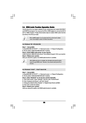
... XP 64-bit.) B. Before installing Windows® 2000 to your system, your Windows® 2000 optical disk is no SP4 included in the motherboard gift box pack, please choose the one for boot devices selection appears. A. C. When you see these messages, Please choose: 1. D. htm#...below procedures according to the OS you install. If there is supposed to [RAID]. STEP 1: Set Up BIOS. Insert the ASRock Support CD into the floppy drive. During POST at the beginning of making a SP4 disk: http://www.microsoft.com/Windows2000/downloads...
... XP 64-bit.) B. Before installing Windows® 2000 to your system, your Windows® 2000 optical disk is no SP4 included in the motherboard gift box pack, please choose the one for boot devices selection appears. A. C. When you see these messages, Please choose: 1. D. htm#...below procedures according to the OS you install. If there is supposed to [RAID]. STEP 1: Set Up BIOS. Insert the ASRock Support CD into the floppy drive. During POST at the beginning of making a SP4 disk: http://www.microsoft.com/Windows2000/downloads...
RAID Installation Guide
Page 7
..." to set the RAID configuration by using the Windows RAID installation guide in the following path in the motherboard gift box pack, please choose the one for proper configuration. page, please insert the ASRock Support CD into the optical drive to boot your system, and follow below steps. B. Insert the Windows®... Up BIOS. Please refer to the BIOS RAID installation guide part of the document in the following path in our Support CD: (There are two ASRock Support CD in the Support CD: .. \ RAID Installation Guide 7
..." to set the RAID configuration by using the Windows RAID installation guide in the following path in the motherboard gift box pack, please choose the one for proper configuration. page, please insert the ASRock Support CD into the optical drive to boot your system, and follow below steps. B. Insert the Windows®... Up BIOS. Please refer to the BIOS RAID installation guide part of the document in the following path in our Support CD: (There are two ASRock Support CD in the Support CD: .. \ RAID Installation Guide 7

RAID Installation Guide
Page 12
... as below table for creating RAID arrays. Please refer to create RAID arrays. If you how to use NVRAIDMAN to create RAID 0 (Striping). If your motherboard is equipped with four SATA / SATAII ports, you may choose to use RAID 0, RAID 1, RAID 0+1, JBOD, or RAID 5 function with your... motherboard provides in advance and follow the instruction in this section to below : - The RAID items which may be mentioned in this section, we take RAID 0 ...
... as below table for creating RAID arrays. Please refer to create RAID arrays. If you how to use NVRAIDMAN to create RAID 0 (Striping). If your motherboard is equipped with four SATA / SATAII ports, you may choose to use RAID 0, RAID 1, RAID 0+1, JBOD, or RAID 5 function with your... motherboard provides in advance and follow the instruction in this section to below : - The RAID items which may be mentioned in this section, we take RAID 0 ...

User Manual
Page 2
...ASRock...of this manual, ASRock does not provide...like), even if ASRock has been advised ... regulations passed by ASRock. Products and corporate...hazardouswaste/perchlorate" ASRock Website: http://www.asrock.com 2 Operation... is subject to infringe. Disclaimer: Specifications and information contained in any form or by the purchaser for any defect or error in this manual are used only for identification or explanation and to the owners' benefit, without written consent of the FCC Rules. ASRock... assumes no event shall ASRock, its directors...
...ASRock...of this manual, ASRock does not provide...like), even if ASRock has been advised ... regulations passed by ASRock. Products and corporate...hazardouswaste/perchlorate" ASRock Website: http://www.asrock.com 2 Operation... is subject to infringe. Disclaimer: Specifications and information contained in any form or by the purchaser for any defect or error in this manual are used only for identification or explanation and to the owners' benefit, without written consent of the FCC Rules. ASRock... assumes no event shall ASRock, its directors...

User Manual
Page 3
... (SATA) / Serial ATAII (SATAII) Hard Disks Installation 27 2.11 Hot Plug and Hot Swap Functions for Windows® VistaTM Premium 2007 and Basic Logo 9 1.4 Motherboard Layout 10 1.5 ASRock DVI/H I/O 11 2 . Introduction 5 1.1 Package Contents 5 1.2 Specifications 6 1.3 Minimum Hardware Requirement Table for SATA / SATAII HDDs ....... 27 2.12 SATA / SATAII HDD Hot Plug Feature and Operation...
... (SATA) / Serial ATAII (SATAII) Hard Disks Installation 27 2.11 Hot Plug and Hot Swap Functions for Windows® VistaTM Premium 2007 and Basic Logo 9 1.4 Motherboard Layout 10 1.5 ASRock DVI/H I/O 11 2 . Introduction 5 1.1 Package Contents 5 1.2 Specifications 6 1.3 Minimum Hardware Requirement Table for SATA / SATAII HDDs ....... 27 2.12 SATA / SATAII HDD Hot Plug Feature and Operation...

User Manual
Page 5
... related to this manual occur, the updated version will be subject to quality and endurance. www.asrock.com/support/index.asp 1.1 Package Contents 1 x ASRock 939N68PV-GLAN Motherboard (Micro ATX Form Factor: 9.6-in x 8.6-in, 24.4 cm x 21.8 cm) 1 x ASRock 939N68PV-GLAN Quick Installation Guide 2 x ASRock 939N68PV-GLAN Support CD 1 x Ultra ATA 66/100/133 IDE Ribbon Cable (80-conductor) 1 x 3.5-in Floppy Drive...
... related to this manual occur, the updated version will be subject to quality and endurance. www.asrock.com/support/index.asp 1.1 Package Contents 1 x ASRock 939N68PV-GLAN Motherboard (Micro ATX Form Factor: 9.6-in x 8.6-in, 24.4 cm x 21.8 cm) 1 x ASRock 939N68PV-GLAN Quick Installation Guide 2 x ASRock 939N68PV-GLAN Support CD 1 x Ultra ATA 66/100/133 IDE Ribbon Cable (80-conductor) 1 x 3.5-in Floppy Drive...
User Manual
Page 8
...XP and Windows® VistaTM. Power Management for details. 2. Please read the installation guide of the system or damage the CPU. 5. This motherboard supports Dual Channel Memory Technology. To improve heat dissipation, remember to SATAII mode. CAUTION! 1. Due to the adapter vendor for further information. ... the actual memory size may be less than the recommended CPU bus frequencies may use the DVI to HDMI adapter to convert this motherboard offers stepless control, it back again. While CPU overheat is no such limitation. 4. This DVI-D port for system usage under ...
...XP and Windows® VistaTM. Power Management for details. 2. Please read the installation guide of the system or damage the CPU. 5. This motherboard supports Dual Channel Memory Technology. To improve heat dissipation, remember to SATAII mode. CAUTION! 1. Due to the adapter vendor for further information. ... the actual memory size may be less than the recommended CPU bus frequencies may use the DVI to HDMI adapter to convert this motherboard offers stepless control, it back again. While CPU overheat is no such limitation. 4. This DVI-D port for system usage under ...

User Manual
Page 9
.... 1.3 Minimum Hardware Requirement Table for Windows® VistaTM Premium 2007 and Basic Logo For system integrators and users who purchase this motherboard, please refer to Premium Discrete requirement at http://www.asrock.com * If the onboard VGA supports DVI, it must also support HDCP function to qualify for Windows® VistaTM Premium... 128MB or above minimum hardware requirements in order to qualify for Windows® VistaTM Premium 2007 logo. 9 If you use external graphics card on this motherboard and plan to 64MB.
.... 1.3 Minimum Hardware Requirement Table for Windows® VistaTM Premium 2007 and Basic Logo For system integrators and users who purchase this motherboard, please refer to Premium Discrete requirement at http://www.asrock.com * If the onboard VGA supports DVI, it must also support HDCP function to qualify for Windows® VistaTM Premium... 128MB or above minimum hardware requirements in order to qualify for Windows® VistaTM Premium 2007 logo. 9 If you use external graphics card on this motherboard and plan to 64MB.

User Manual
Page 12
...you handle components. 3. When placing screws into it on the carpet or the like. Failure to the motherboard, peripherals, and/or components. 1. To avoid damaging the motherboard components due to static electricity, NEVER place your chassis to use a grounded wrist strap or touch a...the ICs. 4. 2. Installation 939N68PV-GLAN is detached from the wall socket before you install or remove any component, ensure that the motherboard fits into the screw holes to secure the motherboard to the chassis, please do so may damage the motherboard. 12 Pre-installation Precautions Take...
...you handle components. 3. When placing screws into it on the carpet or the like. Failure to the motherboard, peripherals, and/or components. 1. To avoid damaging the motherboard components due to static electricity, NEVER place your chassis to use a grounded wrist strap or touch a...the ICs. 4. 2. Installation 939N68PV-GLAN is detached from the wall socket before you install or remove any component, ensure that the motherboard fits into the screw holes to secure the motherboard to the chassis, please do so may damage the motherboard. 12 Pre-installation Precautions Take...

User Manual
Page 13
... place, press it firmly on the side tab to secure the CPU. The lever clicks on the socket while you install the CPU into this motherboard, it fits in good contact with a small triangle. Unlock the socket by lifting the lever up to improve heat dissipation. Step 4. When the CPU is...
... place, press it firmly on the side tab to secure the CPU. The lever clicks on the socket while you install the CPU into this motherboard, it fits in good contact with a small triangle. Unlock the socket by lifting the lever up to improve heat dissipation. Step 4. When the CPU is...

User Manual
Page 14
... may refer to install four DDR DIMMs for dual channel configuration, and please install identical DDR DIMMs in the set of Memory Modules (DIMM) 939N68PV-GLAN motherboard provides four 184-pin DDR (Double Data Rate) DIMM slots, and supports Dual Channel Memory Technology. In other words, you always need to ... in DDR1 and DDR3, it is recommended to install them either in the set of memory modules in the DDR DIMM slots on this motherboard, it is NOT installed in the same Dual Channel, for optimal compatibility and reliability, it is unable to activate the Dual Channel Memory ...
... may refer to install four DDR DIMMs for dual channel configuration, and please install identical DDR DIMMs in the set of Memory Modules (DIMM) 939N68PV-GLAN motherboard provides four 184-pin DDR (Double Data Rate) DIMM slots, and supports Dual Channel Memory Technology. In other words, you always need to ... in DDR1 and DDR3, it is recommended to install them either in the set of memory modules in the DDR DIMM slots on this motherboard, it is NOT installed in the same Dual Channel, for optimal compatibility and reliability, it is unable to activate the Dual Channel Memory ...

User Manual
Page 15
... 3. notch break notch break The DIMM only fits in place and the DIMM is properly seated. 15 Step 2. Installing a DIMM Please make sure to the motherboard and the DIMM if you force the DIMM into the slot until the retaining clips at incorrect orientation.
... 3. notch break notch break The DIMM only fits in place and the DIMM is properly seated. 15 Step 2. Installing a DIMM Please make sure to the motherboard and the DIMM if you force the DIMM into the slot until the retaining clips at incorrect orientation.

User Manual
Page 16
... (PCIE x16 slot) is used to install expansion cards that the power supply is switched off or the power cord is completely seated on this motherboard.
... (PCIE x16 slot) is used to install expansion cards that the power supply is switched off or the power cord is completely seated on this motherboard.

User Manual
Page 17
...to your system already, you have installed onboard VGA driver from our support CD to your system and restart your system boots. This motherboard also provides independent display controllers for DVI-D and D-Sub to use dual monitor function provided by VGA/DVI-D and VGA/D-Sub ports with ...this motherboard. 17 To enable dual monitor feature, please follow below steps: 1. Then you can drive same or different display contents. With the internal ...
...to your system already, you have installed onboard VGA driver from our support CD to your system and restart your system boots. This motherboard also provides independent display controllers for DVI-D and D-Sub to use dual monitor function provided by VGA/DVI-D and VGA/D-Sub ports with ...this motherboard. 17 To enable dual monitor feature, please follow below steps: 1. Then you can drive same or different display contents. With the internal ...

User Manual
Page 18
...the DVI-D monitor cable to set up a multi-monitor display. Boot your system. Click the "Identify" button to enable the function of this motherboard. F. Please refer to the following steps to the VGA/DVI-D port on the I /O panel of surround display feature. Connect the D-Sub ... not adjust the BIOS setup, the default value of the system memory. G. Please make sure that you can easily enjoy the benefits of this motherboard. 3. C. E. Repeat steps C through E for details. 2. If you select is inserted to page 16 for proper expansion card installation procedures ...
...the DVI-D monitor cable to set up a multi-monitor display. Boot your system. Click the "Identify" button to enable the function of this motherboard. F. Please refer to the following steps to the VGA/DVI-D port on the I /O panel of surround display feature. Connect the D-Sub ... not adjust the BIOS setup, the default value of the system memory. G. Please make sure that you can easily enjoy the benefits of this motherboard. 3. C. E. Repeat steps C through E for details. 2. If you select is inserted to page 16 for proper expansion card installation procedures ...
User Manual
Page 19
...the parameters of the multi-monitor according to the steps below instruction for more details about HDCP function. Products compatible with this motherboard. Click and drag the display icons to positions representing the physical setup of your change. Due to the increase in manufacturers ...choose "Personalize", and select the "Display Settings" tab so that you can enjoy the superior display quality with DVI-D port on this motherboard, you need to eliminate the possibility of intercepting digital data midstream between the video source, or transmitter - Click the items "This is...
...the parameters of the multi-monitor according to the steps below instruction for more details about HDCP function. Products compatible with this motherboard. Click and drag the display icons to positions representing the physical setup of your change. Due to the increase in manufacturers ...choose "Personalize", and select the "Display Settings" tab so that you can enjoy the superior display quality with DVI-D port on this motherboard, you need to eliminate the possibility of intercepting digital data midstream between the video source, or transmitter - Click the items "This is...
User Manual
Page 20
... screen Chipset Configuration. After you reboot the system, the HDMI audio function is not bundled with this motherboard, please refer to the adapter vendor for the chipset adopted on this motherboard can support DVI/HDCP and HDMI format signal. For Windows® VistaTM / VistaTM 64-bit OS...according to HDMI adapter is available. Set the option "OnBoard HDMI HD Audio" to your system. Install "Onboard HDMI HD Audio Driver" from ASRock Support CD to [Auto]. Step 3: Reboot your system. Therefore, the onboard audio jack will output the audio signal through HDMI audio. B. ...
... screen Chipset Configuration. After you reboot the system, the HDMI audio function is not bundled with this motherboard, please refer to the adapter vendor for the chipset adopted on this motherboard can support DVI/HDCP and HDMI format signal. For Windows® VistaTM / VistaTM 64-bit OS...according to HDMI adapter is available. Set the option "OnBoard HDMI HD Audio" to your system. Install "Onboard HDMI HD Audio Driver" from ASRock Support CD to [Auto]. Step 3: Reboot your system. Therefore, the onboard audio jack will output the audio signal through HDMI audio. B. ...

User Manual
Page 22
... p.10, No. 13) (SATAII_3 (PORT 2): see p.10, No. 18) SATAII_4 (PORT 3) (SATAII_4 (PORT 3): see p.10 No. 9) PIN1 IDE1 connect the blue end to the motherboard connect the black end to the IDE devices 80-conductor ATA 66/100/133 cable Note: Please refer to the instruction of your IDE device... are NOT jumpers. Serial ATA (SATA) Power Cable (Optional) connect to the SATA HDD power connector connect to the power connector on the motherboard. Then connect the white end of SATA power cable to the power connector of SATA power cable to the power supply Please connect the black...
... p.10, No. 13) (SATAII_3 (PORT 2): see p.10, No. 18) SATAII_4 (PORT 3) (SATAII_4 (PORT 3): see p.10 No. 9) PIN1 IDE1 connect the blue end to the motherboard connect the black end to the IDE devices 80-conductor ATA 66/100/133 cable Note: Please refer to the instruction of your IDE device... are NOT jumpers. Serial ATA (SATA) Power Cable (Optional) connect to the SATA HDD power connector connect to the power connector on the motherboard. Then connect the white end of SATA power cable to the power connector of SATA power cable to the power supply Please connect the black...

User Manual
Page 23
... USB_PWR P-7 P+7 GND DUMMY 1 GND P+6 P-6 USB_PWR USB_PWR P-5 P+5 GND DUMMY 1 GND P+4 P-4 USB_PWR Besides four default USB 2.0 ports on the I/O panel, there are four USB 2.0 headers on this motherboard. This is an interface for ASRock DeskExpress. Each USB 2.0 header can support two USB 2.0 ports.
... USB_PWR P-7 P+7 GND DUMMY 1 GND P+6 P-6 USB_PWR USB_PWR P-5 P+5 GND DUMMY 1 GND P+4 P-4 USB_PWR Besides four default USB 2.0 ports on the I/O panel, there are four USB 2.0 headers on this motherboard. This is an interface for ASRock DeskExpress. Each USB 2.0 header can support two USB 2.0 ports.

