RAID Installation Guide
Page 2
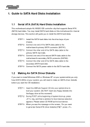
...SATA data cable to SATA Hard Disks Installation 1.1 Serial ATA (SATA) Hard Disks Installation This motherboard adopts ALi M5283 IDE controller chip that supports Serial ATA (SATA) hard disks. Guide to the motherboard's secondary SATA connector (SATA2). STEP 4: Connect one end of system boot-up, press key,... will guide you to install the SATA hard disks. STEP 1: Insert the ASRock Support CD into your system. (Do NOT insert any floppy diskette into the drive bays of the SATA data cable to the motherboard's primary SATA connector (SATA1). STEP 3: When you see the message on ...
...SATA data cable to SATA Hard Disks Installation 1.1 Serial ATA (SATA) Hard Disks Installation This motherboard adopts ALi M5283 IDE controller chip that supports Serial ATA (SATA) hard disks. Guide to the motherboard's secondary SATA connector (SATA2). STEP 4: Connect one end of system boot-up, press key,... will guide you to install the SATA hard disks. STEP 1: Insert the ASRock Support CD into your system. (Do NOT insert any floppy diskette into the drive bays of the SATA data cable to the motherboard's primary SATA connector (SATA1). STEP 3: When you see the message on ...
RAID Installation Guide
Page 4
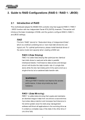
... it contains a complete copy of the same model and capacity when creating a RAID set. This section will double the data transfer rate of RAID This motherboard adopts ALi M5283 IDE controller chip that supports RAID 0 / RAID 1 / JBOD function with two independent Serial ATA (SATA) channels. Although RAID 0 function can improve the...
... it contains a complete copy of the same model and capacity when creating a RAID set. This section will double the data transfer rate of RAID This motherboard adopts ALi M5283 IDE controller chip that supports RAID 0 / RAID 1 / JBOD function with two independent Serial ATA (SATA) channels. Although RAID 0 function can improve the...
User Manual
Page 3
... ATA (SATA) / Serial ATAII (SATAII) Hard Disks Installation 24 2.10 Hot Plug and Hot Swap Functions for PCI Express Slot (PCI Express x16 10 1.5 Motherboard Layout 11 1.6 ASRock 8CH I/O 12 2 . Introduction 5 1.1 Package Contents 5 1.2 Specifications 6 1.3 Minimum Hardware Requirement Table for Windows® VistaTM Logo 9 1.4 Supported ATi X300 and X300SE Series PCI Express VGA...
... ATA (SATA) / Serial ATAII (SATAII) Hard Disks Installation 24 2.10 Hot Plug and Hot Swap Functions for PCI Express Slot (PCI Express x16 10 1.5 Motherboard Layout 11 1.6 ASRock 8CH I/O 12 2 . Introduction 5 1.1 Package Contents 5 1.2 Specifications 6 1.3 Minimum Hardware Requirement Table for Windows® VistaTM Logo 9 1.4 Supported ATi X300 and X300SE Series PCI Express VGA...
User Manual
Page 5
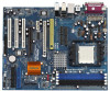
... 3 and 4 contain the configuration guide to BIOS setup and information of the motherboard and step-bystep guide to quality and endurance. ASRock website http://www.asrock.com 1.1 Package Contents 1 x ASRock 939Dual-VSTA Motherboard (ATX Form Factor: 12.0-in x 9.6-in, 30.5 cm x 24.4 cm) 1 x ASRock 939Dual-VSTA Quick Installation Guide 1 x ASRock 939Dual-VSTA Support CD 1 x Ultra ATA 66/100/133 IDE Ribbon Cable (80...
... 3 and 4 contain the configuration guide to BIOS setup and information of the motherboard and step-bystep guide to quality and endurance. ASRock website http://www.asrock.com 1.1 Package Contents 1 x ASRock 939Dual-VSTA Motherboard (ATX Form Factor: 12.0-in x 9.6-in, 30.5 cm x 24.4 cm) 1 x ASRock 939Dual-VSTA Quick Installation Guide 1 x ASRock 939Dual-VSTA Support CD 1 x Ultra ATA 66/100/133 IDE Ribbon Cable (80...
User Manual
Page 8
...To improve heat dissipation, remember to SATAII mode. Please check the table on page 15 for details. 2. This motherboard supports Dual Channel Memory Technology. Frequencies other than the recommended CPU bus frequencies may cause permanent damage! 8. Before you.... 3. We will automatically shutdown. This motherboard supports Untied Overclocking Technology. For the proper installation of this motherboard offers stepless control, it back again. ASRock website http://www.asrock.com 8 CAUTION! 1. For audio output, this motherboard supports both stereo and mono modes. For...
...To improve heat dissipation, remember to SATAII mode. Please check the table on page 15 for details. 2. This motherboard supports Dual Channel Memory Technology. Frequencies other than the recommended CPU bus frequencies may cause permanent damage! 8. Before you.... 3. We will automatically shutdown. This motherboard supports Untied Overclocking Technology. For the proper installation of this motherboard offers stepless control, it back again. ASRock website http://www.asrock.com 8 CAUTION! 1. For audio output, this motherboard supports both stereo and mono modes. For...

User Manual
Page 9
CPU Memory VGA Athlon 3000+ 512MB Single Channel DX9.0 with WDDM Driver with 128bit VGA memory (Premium) with 64bit VGA memory (Basic) 9 Please adopt the CPU, memory, and VGA that we suggest. 1.3 Minimum Hardware Requirement Table for Windows® VistaTM Premium and Basic Logo For system integrators and users who purchase this motherboard and plan to submit Windows® VistaTM Premium and Basic logo, please follow the below table for minimum hardware requirement.
CPU Memory VGA Athlon 3000+ 512MB Single Channel DX9.0 with WDDM Driver with 128bit VGA memory (Premium) with 64bit VGA memory (Basic) 9 Please adopt the CPU, memory, and VGA that we suggest. 1.3 Minimum Hardware Requirement Table for Windows® VistaTM Premium and Basic Logo For system integrators and users who purchase this motherboard and plan to submit Windows® VistaTM Premium and Basic logo, please follow the below table for minimum hardware requirement.

User Manual
Page 13
... touch the ICs. 4. Before you install or remove any component. 2. 2. Before you uninstall any motherboard settings. Installation 939Dual-VSTA is detached from the wall socket before you install motherboard components or change any component, place it . Whenever you install the motherboard, study the configuration of the following precautions before you handle components. 3. Pre-installation Precautions...
... touch the ICs. 4. Before you install or remove any component. 2. 2. Before you uninstall any motherboard settings. Installation 939Dual-VSTA is detached from the wall socket before you install motherboard components or change any component, place it . Whenever you install the motherboard, study the configuration of the following precautions before you handle components. 3. Pre-installation Precautions...

User Manual
Page 14
Step 4. The lever clicks on the socket while you install the CPU into this motherboard, it is locked. You also need to spray thermal grease between the CPU and the heatsink to the CPU FAN connector (CPU_FAN1, see Page 11, ...
Step 4. The lever clicks on the socket while you install the CPU into this motherboard, it is locked. You also need to spray thermal grease between the CPU and the heatsink to the CPU FAN connector (CPU_FAN1, see Page 11, ...
User Manual
Page 15
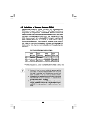
... in the set of the same color. If only one memory module or three memory modules are installed in the DDR DIMM slots on this motherboard, it is recommended to install identical (the same brand, speed, size and chip-type) DDR DIMM pair in Dual Channel A (DDR1 and ...you have to install two memory modules, for dual channel configuration, and please install identical DDR DIMMs in the slots of Memory Modules (DIMM) 939Dual-VSTA motherboard provides four 184-pin DDR (Double Data Rate) DIMM slots, and supports Dual Channel Memory Technology. For dual channel configuration, you want to ...
... in the set of the same color. If only one memory module or three memory modules are installed in the DDR DIMM slots on this motherboard, it is recommended to install identical (the same brand, speed, size and chip-type) DDR DIMM pair in Dual Channel A (DDR1 and ...you have to install two memory modules, for dual channel configuration, and please install identical DDR DIMMs in the slots of Memory Modules (DIMM) 939Dual-VSTA motherboard provides four 184-pin DDR (Double Data Rate) DIMM slots, and supports Dual Channel Memory Technology. For dual channel configuration, you want to ...

User Manual
Page 16
... 2. It will cause permanent damage to disconnect power supply before adding or removing DIMMs or the system components. Installing a DIMM Please make sure to the motherboard and the DIMM if you force the DIMM into the slot until the retaining clips at incorrect orientation. Step 3.
... 2. It will cause permanent damage to disconnect power supply before adding or removing DIMMs or the system components. Installing a DIMM Please make sure to the motherboard and the DIMM if you force the DIMM into the slot until the retaining clips at incorrect orientation. Step 3.
User Manual
Page 17
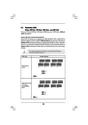
... upgrade your AMD K8 939-Pin CPU to AM2 940Pin CPU, it ! Please do NOT insert any AGP card into this future CPU Port on ASRock AM2CPU Board) 2 1 J3 2 1 J1 2 1 J4 2 1 J2 1_2 J11 1_2 J10 1_2 J9 2 1 J7 2 1 J5 2 1 J8 2 1 J6 17 This yellow-colored Future CPU ...Default) Jumper Settings 3 2 J3 3 2 J1 3 2 J4 3 2 J2 3 2 J7 3 2 J5 3 2 J8 3 2 J6 2_3 J11 2_3 J10 2_3 J9 AM2 940-Pin CPU (Using add-on 939Dual-VSTA motherboard. Please refer to adjust the jumper settings for the correct jumper settings. 2.4 Expansion Slots (Future CPU Port, PCI Slots, PCIE Slots, and AGP Slot) There...
... upgrade your AMD K8 939-Pin CPU to AM2 940Pin CPU, it ! Please do NOT insert any AGP card into this future CPU Port on ASRock AM2CPU Board) 2 1 J3 2 1 J1 2 1 J4 2 1 J2 1_2 J11 1_2 J10 1_2 J9 2 1 J7 2 1 J5 2 1 J8 2 1 J6 17 This yellow-colored Future CPU ...Default) Jumper Settings 3 2 J3 3 2 J1 3 2 J4 3 2 J2 3 2 J7 3 2 J5 3 2 J8 3 2 J6 2_3 J11 2_3 J10 2_3 J9 AM2 940-Pin CPU (Using add-on 939Dual-VSTA motherboard. Please refer to adjust the jumper settings for the correct jumper settings. 2.4 Expansion Slots (Future CPU Port, PCI Slots, PCIE Slots, and AGP Slot) There...

User Manual
Page 18
... sure that you removing the jumper caps more easily. Step 4. Step 5. Step 6. Replace the system cover. 18 For the information of your motherboard is unplugged. For the voltage information of the compatible PCI Express VGA cards, please refer to the "Supported ATi X300 and X300SE Series PCI Express... you may cause permanent damage! It may use the tool, Jumper Cap Remover, to help you intend to use. The ASRock AGP slot has a special design of this motherboard! PCI Slots: PCI slots are used to use . This Jumper Cap Remover is used for PCI Express cards with x16 ...
... sure that you removing the jumper caps more easily. Step 4. Step 5. Step 6. Replace the system cover. 18 For the information of your motherboard is unplugged. For the voltage information of the compatible PCI Express VGA cards, please refer to the "Supported ATi X300 and X300SE Series PCI Express... you may cause permanent damage! It may use the tool, Jumper Cap Remover, to help you intend to use. The ASRock AGP slot has a special design of this motherboard! PCI Slots: PCI slots are used to use . This Jumper Cap Remover is used for PCI Express cards with x16 ...
User Manual
Page 19
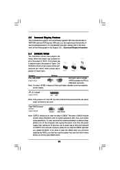
... no jumper cap is placed on pins, the jumper is "Open". Note: To select +5VSB, it down before you can work. 2.5 Surround Display Feature This motherboard supports Surround Display upgrade. When the jumper cap is placed on pins, the jumper is "Short". To clear and reset the system parameters to enable...
... no jumper cap is placed on pins, the jumper is "Open". Note: To select +5VSB, it down before you can work. 2.5 Surround Display Feature This motherboard supports Surround Display upgrade. When the jumper cap is placed on pins, the jumper is "Short". To clear and reset the system parameters to enable...

User Manual
Page 20
... data cables for internal storage devices. Please refer to the instruction of the motherboard! • Floppy Connector (33-pin FLOPPY1) (see p.11 No. 16) PIN1 IDE1 PIN1 IDE2 connect the blue... end to the motherboard connect the black end to the secondary IDE connector (IDE2, black). The current SATAII interface allows...IDE devices 80-conductor ATA 66/100/133 cable Note: If you use only one IDE device on this motherboard, please set the IDE device as "Master". The current SATA interface allows up to 1.5 Gb/s data...
... data cables for internal storage devices. Please refer to the instruction of the motherboard! • Floppy Connector (33-pin FLOPPY1) (see p.11 No. 16) PIN1 IDE1 PIN1 IDE2 connect the blue... end to the motherboard connect the black end to the secondary IDE connector (IDE2, black). The current SATAII interface allows...IDE devices 80-conductor ATA 66/100/133 cable Note: If you use only one IDE device on this motherboard, please set the IDE device as "Master". The current SATA interface allows up to 1.5 Gb/s data...

User Manual
Page 21
... allows convenient connection and control of SATA power cable to the SATA / SATAII hard disk or the SATA / SATAII connector on this motherboard. This is one USB 2.0 header on the motherboard. O U T- This USB 2.0 header can be connected to the power connector of the power supply. L GND A U D - Then connect the white end of...
... allows convenient connection and control of SATA power cable to the SATA / SATAII hard disk or the SATA / SATAII connector on this motherboard. This is one USB 2.0 header on the motherboard. O U T- This USB 2.0 header can be connected to the power connector of the power supply. L GND A U D - Then connect the white end of...
User Manual
Page 24
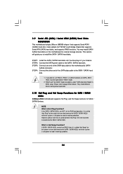
...SATAII hard disk. 1. If the SATA / SATAII HDDs are NOT set for RAID configuration, it is called "Hot Swap" for the action to the motherboard's SATA / SATAII connector. What is Hot Plug Function? STEP 1: Install the SATA / SATAII hard disks into the SATA / SATAII HDD. If ...What is Hot Swap Function? They need different drivers during actual operation. 2.10 Hot Plug and Hot Swap Functions for SATA / SATAII HDDs 939Dual-VSTA motherboard supports Hot Plug and Hot Swap functions for SATA / SATAII Devices. This section will guide you plan to the SATA / SATAII hard disk...
...SATAII hard disk. 1. If the SATA / SATAII HDDs are NOT set for RAID configuration, it is called "Hot Swap" for the action to the motherboard's SATA / SATAII connector. What is Hot Plug Function? STEP 1: Install the SATA / SATAII hard disks into the SATA / SATAII HDD. If ...What is Hot Swap Function? They need different drivers during actual operation. 2.10 Hot Plug and Hot Swap Functions for SATA / SATAII HDDs 939Dual-VSTA motherboard supports Hot Plug and Hot Swap functions for SATA / SATAII Devices. This section will guide you plan to the SATA / SATAII hard disk...

User Manual
Page 27
... choose among the selections on the menu bar, and then press to fixed AGP / PCI / PCIE buses. Before you install. 2.16 Untied Overclocking Technology This motherboard supports Untied Overclocking Technology, which means during overclocking, but AGP / PCI / PCIE buses are for reference purpose only, and they may not exactly match what... [Auto] to enter the BIOS SETUP UTILITY after POST, restart the system by pressing + + , or by turning the system off and then back on the motherboard stores the BIOS SETUP UTILITY.
... choose among the selections on the menu bar, and then press to fixed AGP / PCI / PCIE buses. Before you install. 2.16 Untied Overclocking Technology This motherboard supports Untied Overclocking Technology, which means during overclocking, but AGP / PCI / PCIE buses are for reference purpose only, and they may not exactly match what... [Auto] to enter the BIOS SETUP UTILITY after POST, restart the system by pressing + + , or by turning the system off and then back on the motherboard stores the BIOS SETUP UTILITY.

User Manual
Page 29
... the future, you may set the configurations for CPU Select Screen Select Item Enter Go to AM2 940-Pin CPU by installing an add-on ASRock AM2CPU Board into future CPU Port on this motherboard 3.3 Advanced Screen In this section may cause the system to malfunction.
... the future, you may set the configurations for CPU Select Screen Select Item Enter Go to AM2 940-Pin CPU by installing an add-on ASRock AM2CPU Board into future CPU Port on this motherboard 3.3 Advanced Screen In this section may cause the system to malfunction.
User Manual
Page 40
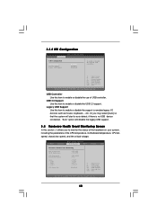
..., American Megatrends, Inc. 40 USB 2.0 Support Use this item to enable or disable the support to enable or disable the use of the CPU temperature, motherboard temperature, CPU fan speed, chassis fan speed, and the critical voltage. etc. if there is no USB device connected, "Auto" option will start to enable...
..., American Megatrends, Inc. 40 USB 2.0 Support Use this item to enable or disable the support to enable or disable the use of the CPU temperature, motherboard temperature, CPU fan speed, chassis fan speed, and the critical voltage. etc. if there is no USB device connected, "Auto" option will start to enable...
User Manual
Page 44
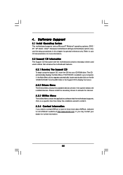
... the file "ASSETUP.EXE" from the BIN folder in this chapter for more about ASRock, welcome to know more information. 4.2 Support CD Information The Support CD that came with the motherboard contains necessary drivers and useful utilities that the motherboard supports. 4. Please install the necessary drivers to display the menus. 4.2.2 Drivers Menu The...
... the file "ASSETUP.EXE" from the BIN folder in this chapter for more about ASRock, welcome to know more information. 4.2 Support CD Information The Support CD that came with the motherboard contains necessary drivers and useful utilities that the motherboard supports. 4. Please install the necessary drivers to display the menus. 4.2.2 Drivers Menu The...

