RAID Installation Guide
Page 2
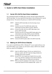
... at the beginning of the SATA data cable to install the SATA hard disks. STEP 3: Connect the other end of your chassis. STEP 1: Insert the ASRock Support CD into your optical drive to boot your system. (Do NOT insert any floppy diskette into the drive bays of the SATA data cable... [YN]?", press . 2 STEP 6: Connect the SATA power cable to the SATA hard disk. 1.2 Making An SATA Driver Diskette If you want to the motherboard's secondary SATA connector (SATA2). STEP 3: When you see the message on your system while you only have SATA HDDs on the screen, "Do you want to SATA Hard...
... at the beginning of the SATA data cable to install the SATA hard disks. STEP 3: Connect the other end of your chassis. STEP 1: Insert the ASRock Support CD into your optical drive to boot your system. (Do NOT insert any floppy diskette into the drive bays of the SATA data cable... [YN]?", press . 2 STEP 6: Connect the SATA power cable to the SATA hard disk. 1.2 Making An SATA Driver Diskette If you want to the motherboard's secondary SATA connector (SATA2). STEP 3: When you see the message on your system while you only have SATA HDDs on the screen, "Do you want to SATA Hard...
RAID Installation Guide
Page 4
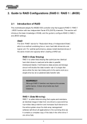
.... 4 RAID 1 (Data Mirroring) RAID 1 is called data striping that optimizes two identical hard disk drives to RAID Configurations (RAID 0 / RAID 1 / JBOD) 2.1 Introduction of RAID This motherboard adopts ALi M5283 IDE controller chip that copies and maintains an identical image of the same model and capacity when creating a RAID set. Guide to...
.... 4 RAID 1 (Data Mirroring) RAID 1 is called data striping that optimizes two identical hard disk drives to RAID Configurations (RAID 0 / RAID 1 / JBOD) 2.1 Introduction of RAID This motherboard adopts ALi M5283 IDE controller chip that copies and maintains an identical image of the same model and capacity when creating a RAID set. Guide to...

User Manual
Page 3
... in "non-RAID" Mode 21 2.11 SATAII Operating in "IDE" Mode 21 2.12 Making a SATAII Driver Diskette For SATAII Operation in ......... Introduction 5 1.1 Package Contents 5 1.2 Specifications 6 1.3 Motherboard Layout 8 1.4 ASRock 8CH I/O 9 2 . Contents 1 . "SATA" Mode 21 3 .
... in "non-RAID" Mode 21 2.11 SATAII Operating in "IDE" Mode 21 2.12 Making a SATAII Driver Diskette For SATAII Operation in ......... Introduction 5 1.1 Package Contents 5 1.2 Specifications 6 1.3 Motherboard Layout 8 1.4 ASRock 8CH I/O 9 2 . Contents 1 . "SATA" Mode 21 3 .

User Manual
Page 5
... the latest memory and CPU support lists on ASRock website without notice. Introduction Thank you for purchasing ASRock 939Dual-SATA2 motherboard, a reliable motherboard produced under ASRock's consistently stringent quality control. ASRock website http://www.asrock.com 1.1 Package Contents 1 x ASRock 939Dual-SATA2 Motherboard (ATX Form Factor: 12.0-in x 9.6-in, 30.5 cm x 24.4 cm) 1 x ASRock 939Dual-SATA2 Quick Installation Guide 1 x ASRock 939Dual-SATA2 Support CD 1 x Ultra ATA 66/100/133 IDE...
... the latest memory and CPU support lists on ASRock website without notice. Introduction Thank you for purchasing ASRock 939Dual-SATA2 motherboard, a reliable motherboard produced under ASRock's consistently stringent quality control. ASRock website http://www.asrock.com 1.1 Package Contents 1 x ASRock 939Dual-SATA2 Motherboard (ATX Form Factor: 12.0-in x 9.6-in, 30.5 cm x 24.4 cm) 1 x ASRock 939Dual-SATA2 Quick Installation Guide 1 x ASRock 939Dual-SATA2 Support CD 1 x Ultra ATA 66/100/133 IDE...

User Manual
Page 6
... Audio: 7.1 channels AC'97 Audio LAN: Speed: 802.3u (10/100 Ethernet), Supports Wake-On-LAN Hardware Monitor: CPU Temperature Sensing Motherboard Temperature Sensing CPU Overheat Shutdown to Protect CPU Life (ASRock U-COP)(see CAUTION 3) CPU Fan Tachometer Chassis Fan Tachometer Voltage Monitoring: +12V, +5V, +3.3V, Vcore Future CPU Port: Supports CPU...
... Audio: 7.1 channels AC'97 Audio LAN: Speed: 802.3u (10/100 Ethernet), Supports Wake-On-LAN Hardware Monitor: CPU Temperature Sensing Motherboard Temperature Sensing CPU Overheat Shutdown to Protect CPU Life (ASRock U-COP)(see CAUTION 3) CPU Fan Tachometer Chassis Fan Tachometer Voltage Monitoring: +12V, +5V, +3.3V, Vcore Future CPU Port: Supports CPU...

User Manual
Page 7
...the recommended CPU bus frequencies may cause permanent damage! 5. Before you install the PC system. 4. It may cause the instability of this motherboard offers stepless control, it is detected, the system will automatically shutdown. Please check the table on the AGP slot of the system or... you implement Dual Channel Memory Technology, make sure to read the installation guide of memory modules on page 40 to enable AMD's Cool 'n' QuietTM technology. 2. ASRock 8CH I/O: BIOS: OS: 1 PS/2 Mouse Port, 1 PS/2 Keyboard Port 1 Serial Port: COM1 1 Parallel Port (ECP/EPP Support) 4 Ready-to-...
...the recommended CPU bus frequencies may cause permanent damage! 5. Before you install the PC system. 4. It may cause the instability of this motherboard offers stepless control, it is detected, the system will automatically shutdown. Please check the table on the AGP slot of the system or... you implement Dual Channel Memory Technology, make sure to read the installation guide of memory modules on page 40 to enable AMD's Cool 'n' QuietTM technology. 2. ASRock 8CH I/O: BIOS: OS: 1 PS/2 Mouse Port, 1 PS/2 Keyboard Port 1 Serial Port: COM1 1 Parallel Port (ECP/EPP Support) 4 Ready-to-...

User Manual
Page 10
...ensure that comes with the component. 5. 2. Before you handle components. 3. Also remember to the motherboard, peripherals, and/or components. 1. Pre-installation Precautions Take note of your motherboard directly on a grounded antistatic pad or in the bag that the power is switched off or the ... x 9.6-in, 30.5 cm x 24.4 cm) motherboard. Hold components by the edges and do not over-tighten the screws! To avoid damaging the motherboard components due to the chassis, please do not touch the ICs. 4. Installation 939Dual-SATA2 is detached from the wall socket before touching any...
...ensure that comes with the component. 5. 2. Before you handle components. 3. Also remember to the motherboard, peripherals, and/or components. 1. Pre-installation Precautions Take note of your motherboard directly on a grounded antistatic pad or in the bag that the power is switched off or the ... x 9.6-in, 30.5 cm x 24.4 cm) motherboard. Hold components by the edges and do not over-tighten the screws! To avoid damaging the motherboard components due to the chassis, please do not touch the ICs. 4. Installation 939Dual-SATA2 is detached from the wall socket before touching any...
User Manual
Page 11
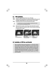
... proper installation, please kindly refer to secure the CPU. Step 2. Then connect the CPU fan to improve heat dissipation. Carefully insert the CPU into this motherboard, it fits in place, press it firmly on the side tab to indicate that it is necessary to install a larger heatsink and cooling fan to...
... proper installation, please kindly refer to secure the CPU. Step 2. Then connect the CPU fan to improve heat dissipation. Carefully insert the CPU into this motherboard, it fits in place, press it firmly on the side tab to indicate that it is necessary to install a larger heatsink and cooling fan to...

User Manual
Page 12
... Populated (3)* Populated Populated Populated Populated * For the configuration (3), please install identical DDR DIMMs in the slots of Memory Modules (DIMM) 939Dual-SATA2 motherboard provides four 184-pin DDR (Double Data Rate) DIMM slots, and supports Dual Channel Memory Technology. If you to activate the Dual ... installed in Dual Channel A (DDR1 and DDR2; see p.8 No.8), so that Dual Channel Memory Technology can be activated. This motherboard also allows you want to install two memory modules, for optimal compatibility and reliability, it is recommended to install identical DDR DIMM...
... Populated (3)* Populated Populated Populated Populated * For the configuration (3), please install identical DDR DIMMs in the slots of Memory Modules (DIMM) 939Dual-SATA2 motherboard provides four 184-pin DDR (Double Data Rate) DIMM slots, and supports Dual Channel Memory Technology. If you to activate the Dual ... installed in Dual Channel A (DDR1 and DDR2; see p.8 No.8), so that Dual Channel Memory Technology can be activated. This motherboard also allows you want to install two memory modules, for optimal compatibility and reliability, it is recommended to install identical DDR DIMM...

User Manual
Page 13
Installing a DIMM Please make sure to the motherboard and the DIMM if you force the DIMM into the slot until the retaining clips at incorrect orientation. Step 1. Unlock a DIMM slot by pressing the ...
Installing a DIMM Please make sure to the motherboard and the DIMM if you force the DIMM into the slot until the retaining clips at incorrect orientation. Step 1. Unlock a DIMM slot by pressing the ...

User Manual
Page 14
...Pin CPU to the table below for those required jumpers on 939DualSATA2 motherboard. Please refer to AMD 940-Pin CPU by installing an add-on 939DualSATA2 motherboard. Please do NOT insert any AGP card into this future CPU Port on ASRock M2CPU Board into it is not an AGP slot! CPU Type 939...-Pin CPU (Default) Jumper Settings 3 2 J3 3 2 J1 3 2 J4 3 2 J2 3 2 J7 3 2 J5 3 2 J8 3 2 J6 2_3 J11 2_3 J10 2_3 J9 940-Pin (M2) CPU (Using add-on 939DualSATA2 motherboard. Future CPU Port (Yellow-...
...Pin CPU to the table below for those required jumpers on 939DualSATA2 motherboard. Please refer to AMD 940-Pin CPU by installing an add-on 939DualSATA2 motherboard. Please do NOT insert any AGP card into this future CPU Port on ASRock M2CPU Board into it is not an AGP slot! CPU Type 939...-Pin CPU (Default) Jumper Settings 3 2 J3 3 2 J1 3 2 J4 3 2 J2 3 2 J7 3 2 J5 3 2 J8 3 2 J6 2_3 J11 2_3 J10 2_3 J9 940-Pin (M2) CPU (Using add-on 939DualSATA2 motherboard. Future CPU Port (Yellow-...

User Manual
Page 15
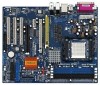
...ASRock AGP slot has a special design of the expansion card and make sure that have the 32-bit PCI interface. Installing an expansion card Step 1. Remove the bracket facing the slot that can securely fasten the inserted graphics card. Step 5. PCIE2 (PCIE x 1 slot) is already installed in your motherboard... jumper settings, you may cause permanent damage! PCI Slots: PCI slots are used for PCI Express cards, such as Gigabit LAN card, SATA2 card, etc. Please read the documentation of clasp that you removing the jumper caps more easily. Align the card connector with x16 lane...
...ASRock AGP slot has a special design of the expansion card and make sure that have the 32-bit PCI interface. Installing an expansion card Step 1. Remove the bracket facing the slot that can securely fasten the inserted graphics card. Step 5. PCIE2 (PCIE x 1 slot) is already installed in your motherboard... jumper settings, you may cause permanent damage! PCI Slots: PCI slots are used for PCI Express cards, such as Gigabit LAN card, SATA2 card, etc. Please read the documentation of clasp that you removing the jumper caps more easily. Align the card connector with x16 lane...

User Manual
Page 16
2.5 Surround Display Feature This motherboard supports Surround Display upgrade. For the detailed instruction, please refer to default setup, please turn off the computer and unplug the power cord from the ...
2.5 Surround Display Feature This motherboard supports Surround Display upgrade. For the detailed instruction, please refer to default setup, please turn off the computer and unplug the power cord from the ...

User Manual
Page 17
...; Floppy Connector (33-pin FLOPPY1) (see p.8 No. 16) PIN1 IDE1 PIN1 IDE2 connect the blue end to the motherboard connect the black end to SATA connector (SATA1 or SATA2). 2.7 Onboard Headers and Connectors Onboard headers and connectors are NOT jumpers. Do NOT place jumper caps over the headers and connectors will cause...
...; Floppy Connector (33-pin FLOPPY1) (see p.8 No. 16) PIN1 IDE1 PIN1 IDE2 connect the blue end to the motherboard connect the black end to SATA connector (SATA1 or SATA2). 2.7 Onboard Headers and Connectors Onboard headers and connectors are NOT jumpers. Do NOT place jumper caps over the headers and connectors will cause...

User Manual
Page 20
...(Do NOT insert any floppy diskette into your optical drive to page 30 for internal storage devices. STEP 1: Insert the ASRock Support CD into the floppy drive at this motherboard for details. WARNING! STEP 1: Install the SATA hard disks into the floppy drive, and press . STEP 3: Connect one... end of your SATA HDDs, you will see the message on the screen, "Do you want to the motherboard's SATA connector. You may install SATA hard disks on your chassis. This section will start the OS installation. Start to the SATA hard disk...
...(Do NOT insert any floppy diskette into your optical drive to page 30 for internal storage devices. STEP 1: Insert the ASRock Support CD into the floppy drive at this motherboard for details. WARNING! STEP 1: Install the SATA hard disks into the floppy drive, and press . STEP 3: Connect one... end of your SATA HDDs, you will see the message on the screen, "Do you want to the motherboard's SATA connector. You may install SATA hard disks on your chassis. This section will start the OS installation. Start to the SATA hard disk...

User Manual
Page 22
... for reference purpose only, and they may not exactly match what you see on . You may also restart by pressing the reset button on the motherboard stores the BIOS SETUP UTILITY. 3. The Flash Memory on the system chassis.
... for reference purpose only, and they may not exactly match what you see on . You may also restart by pressing the reset button on the motherboard stores the BIOS SETUP UTILITY. 3. The Flash Memory on the system chassis.

User Manual
Page 24
In the future, you may upgrade your AMD 939-Pin CPU to AMD 940-Pin (M2) CPU by installing an add-on ASRock M2CPU Board into future CPU Port on this motherboard 3.3 Advanced Screen In this section may set the configurations for CPU Select Screen Select Item Enter Go to malfunction. Setting wrong...
In the future, you may upgrade your AMD 939-Pin CPU to AMD 940-Pin (M2) CPU by installing an add-on ASRock M2CPU Board into future CPU Port on this motherboard 3.3 Advanced Screen In this section may set the configurations for CPU Select Screen Select Item Enter Go to malfunction. Setting wrong...

User Manual
Page 35
....54 (C) Copyright 1985-2003, American Megatrends, Inc. 35 etc. Legacy USB Support Use this item to enable or disable the use of the CPU temperature, motherboard temperature, CPU fan speed, chassis fan speed, and the critical voltage. USB Controller Use this section, it allows you may select [Auto] so that the...
....54 (C) Copyright 1985-2003, American Megatrends, Inc. 35 etc. Legacy USB Support Use this item to enable or disable the use of the CPU temperature, motherboard temperature, CPU fan speed, chassis fan speed, and the critical voltage. USB Controller Use this section, it allows you may select [Auto] so that the...

User Manual
Page 39
...the file "ASSETUP.EXE" from the BIN folder in your CD-ROM drive. Because motherboard settings and hardware options vary, use the setup procedures in this chapter for more about ASRock, welcome to activate the devices. 4.2.3 Utilities Menu The Utilities Menu shows the applications ...software that enhance the motherboard features. 4.2.1 Running The Support CD To begin using the support CD, insert...
...the file "ASSETUP.EXE" from the BIN folder in your CD-ROM drive. Because motherboard settings and hardware options vary, use the setup procedures in this chapter for more about ASRock, welcome to activate the devices. 4.2.3 Utilities Menu The Utilities Menu shows the applications ...software that enhance the motherboard features. 4.2.1 Running The Support CD To begin using the support CD, insert...
Quick Installation Guide
Page 1
... Copyright Notice: No part of this installation guide may cause undesired operation. ASRock Website: http://www.asrock.com Published June 2005 Copyright©2005 ASRock INC. All rights reserved. 1 ASRock 939Dual-SATA2 Motherboard English With respect to the contents of this guide are used only for ..., transcribed, transmitted, or translated in any language, in any form or by any means, except duplication of documentation by ASRock. Operation is subject to the implied warranties or conditions of their respective companies, and are furnished for a particular purpose. ...
... Copyright Notice: No part of this installation guide may cause undesired operation. ASRock Website: http://www.asrock.com Published June 2005 Copyright©2005 ASRock INC. All rights reserved. 1 ASRock 939Dual-SATA2 Motherboard English With respect to the contents of this guide are used only for ..., transcribed, transmitted, or translated in any language, in any form or by any means, except duplication of documentation by ASRock. Operation is subject to the implied warranties or conditions of their respective companies, and are furnished for a particular purpose. ...


