RAID Installation Guide
Page 1
AMD RAID Installation Guide 1. AMD BIOS RAID Installation Guide 2 1.1 Introduction to RAIDXpert from the Internet 17 2.9 Running RAIDXpert without Network Connection 17 1 AMD Windows RAID Installation Guide 10 2.1 Components of RAIDXpert ...
AMD RAID Installation Guide 1. AMD BIOS RAID Installation Guide 2 1.1 Introduction to RAIDXpert from the Internet 17 2.9 Running RAIDXpert without Network Connection 17 1 AMD Windows RAID Installation Guide 10 2.1 Components of RAIDXpert ...

RAID Installation Guide
Page 2
...RAID set the option to the next drive automatically. RAID 10 (Stripe Mirroring) RAID 0 drives can start to use the onboard FastBuild BIOS utility to configure RAID. 1.1 Introduction to one or more hard disk drives into one drive fails. Data is called data striping that ... sustained data transfer rate. However, in our support CD or "Quick Installation Guide", then you make a SATA / SATAII driver diskette, press to enter BIOS setup to set . 1. JBOD JBOD stands for improved performance plus resiliency. RAID 0 (Data Striping) RAID 0 is a method combining two or more ...
...RAID set the option to the next drive automatically. RAID 10 (Stripe Mirroring) RAID 0 drives can start to use the onboard FastBuild BIOS utility to configure RAID. 1.1 Introduction to one or more hard disk drives into one drive fails. Data is called data striping that ... sustained data transfer rate. However, in our support CD or "Quick Installation Guide", then you make a SATA / SATAII driver diskette, press to enter BIOS setup to set . 1. JBOD JBOD stands for improved performance plus resiliency. RAID 0 (Data Striping) RAID 0 is a method combining two or more ...
RAID Installation Guide
Page 4
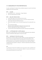
...or more SATA / SATAII HDDs with RAID functions, please follow below steps. D. At the beginning of Windows setup, press F6 to the BIOS RAID installation guide part in this document for proper configuration. B. Then you will be presented. Please refer to install a third-party RAID driver...set RAID configuration, you can start to configure RAID function, you need to generate Serial ATA driver diskette [YN]?", press . Insert the ASRock Support CD into your system. When prompted, insert the SATA / SATAII driver diskette containing AMD RAID driver. The system will start Please insert...
...or more SATA / SATAII HDDs with RAID functions, please follow below steps. D. At the beginning of Windows setup, press F6 to the BIOS RAID installation guide part in this document for proper configuration. B. Then you will be presented. Please refer to install a third-party RAID driver...set RAID configuration, you can start to configure RAID function, you need to generate Serial ATA driver diskette [YN]?", press . Insert the ASRock Support CD into your system. When prompted, insert the SATA / SATAII driver diskette containing AMD RAID driver. The system will start Please insert...
RAID Installation Guide
Page 5
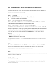
...RAID disk composed of 2 or more SATA / SATAII HDDs with the disk drives installed, the AMD onboard BIOS will display the following path in this document for details. page, please insert the ASRock Support CD into the optical drive again to continue the installation. 1.3.2 Installing Windows 7 / 7 64-... 64-bit / Vista / Vista 64-bit on SATA / SATAII HDDs, you still need to set RAID configuration. Set the "SATA Operation Mode" option to the BIOS RAID installation guide part in our Support CD: .. \ I386 (For Windows 7 / Vista OS) .. \ AMD64 (For Windows 7 64-bit / Vista 64-...
...RAID disk composed of 2 or more SATA / SATAII HDDs with the disk drives installed, the AMD onboard BIOS will display the following path in this document for details. page, please insert the ASRock Support CD into the optical drive again to continue the installation. 1.3.2 Installing Windows 7 / 7 64-... 64-bit / Vista / Vista 64-bit on SATA / SATAII HDDs, you still need to set RAID configuration. Set the "SATA Operation Mode" option to the BIOS RAID installation guide part in our Support CD: .. \ I386 (For Windows 7 / Vista OS) .. \ AMD64 (For Windows 7 64-bit / Vista 64-...
User Manual
Page 4
... 57 4.1 Install Operating System 57 4.2 Support CD Information 57 4.2.1 Running Support CD 57 4.2.2 Drivers Menu 57 4.2.3 Utilities Menu 57 4.2.4 Contact Information 57 4 BIOS SETUP UTILITY 36 3.1 Introduction 36 3.1.1 BIOS Menu Bar 36 3.1.2 Navigation Keys 37 3.2 Main Screen 37 3.3 OC Tweaker Screen 38 3.4 Advanced Screen 42 3.4.1 CPU Configuration 43 3.4.2 Chipset Configuration 44 3.4.3 ACPI...
... 57 4.1 Install Operating System 57 4.2 Support CD Information 57 4.2.1 Running Support CD 57 4.2.2 Drivers Menu 57 4.2.3 Utilities Menu 57 4.2.4 Contact Information 57 4 BIOS SETUP UTILITY 36 3.1 Introduction 36 3.1.1 BIOS Menu Bar 36 3.1.2 Navigation Keys 37 3.2 Main Screen 37 3.3 OC Tweaker Screen 38 3.4 Advanced Screen 42 3.4.1 CPU Configuration 43 3.4.2 Chipset Configuration 44 3.4.3 ACPI...
User Manual
Page 5
... well. Because the motherboard specifications and the BIOS software might be subject to the hardware installation. ASRock website http://www.asrock.com If you are using. www.asrock.com/support/index.asp 1.1 Package Contents ASRock 939A785GMH Motherboard (Micro ATX Form Factor: 9.6-in x 8.6-in, 24.4 cm x 21.8 cm) ASRock 939A785GMH Quick Installation Guide ASRock 939A785GMH Support CD 2 x Serial ATA (SATA) Data...
... well. Because the motherboard specifications and the BIOS software might be subject to the hardware installation. ASRock website http://www.asrock.com If you are using. www.asrock.com/support/index.asp 1.1 Package Contents ASRock 939A785GMH Motherboard (Micro ATX Form Factor: 9.6-in x 8.6-in, 24.4 cm x 21.8 cm) ASRock 939A785GMH Quick Installation Guide ASRock 939A785GMH Support CD 2 x Serial ATA (SATA) Data...

User Manual
Page 7
... - 4 pin 12V power connector - AMI Legal BIOS - ASRock OC Tuner (see CAUTION 8) - ASRock Instant Flash (see CAUTION 6) - Front panel audio connector - 3 x USB 2.0 headers (support 6 USB 2.0 ports) - 8Mb AMI BIOS - Supports jumperfree - OEM) - HD Audio Jack...connector - 1 x IR header - 1 x COM port header - 1 x Print port header - ASRock OC DNA (see CAUTION 10) 7 ASRock APP Charger (see CAUTION 9) - VCCM, NB Voltage Multi-adjustment - OEM and Trial; Rear Panel I/O Connector BIOS Feature Support CD Unique Feature I/O Panel - 1 x PS/2 Keyboard Port - 1 x D-Sub Port...
... - 4 pin 12V power connector - AMI Legal BIOS - ASRock OC Tuner (see CAUTION 8) - ASRock Instant Flash (see CAUTION 6) - Front panel audio connector - 3 x USB 2.0 headers (support 6 USB 2.0 ports) - 8Mb AMI BIOS - Supports jumperfree - OEM) - HD Audio Jack...connector - 1 x IR header - 1 x COM port header - 1 x Print port header - ASRock OC DNA (see CAUTION 10) 7 ASRock APP Charger (see CAUTION 9) - VCCM, NB Voltage Multi-adjustment - OEM and Trial; Rear Panel I/O Connector BIOS Feature Support CD Unique Feature I/O Panel - 1 x PS/2 Keyboard Port - 1 x D-Sub Port...
User Manual
Page 8
... CAUTION 13) * For detailed product information, please visit our website: http://www.asrock.com WARNING Please realize that there is a certain risk involved with overclocking, including adjusting the setting in the BIOS, applying Untied Overclocking Technology, or using the thirdparty overclocking tools. CPU Temperature Sensing Monitor...system stability, or even cause damage to the components and devices of your own risk and expense. Hybrid Booster: - ASRock U-COP (see CAUTION 12) - Boot Failure Guard (B.F.G.) Hardware - FCC, CE, WHQL - CPU/Chassis/Power Fan Tachometer - -
... CAUTION 13) * For detailed product information, please visit our website: http://www.asrock.com WARNING Please realize that there is a certain risk involved with overclocking, including adjusting the setting in the BIOS, applying Untied Overclocking Technology, or using the thirdparty overclocking tools. CPU Temperature Sensing Monitor...system stability, or even cause damage to the components and devices of your own risk and expense. Hybrid Booster: - ASRock U-COP (see CAUTION 12) - Boot Failure Guard (B.F.G.) Hardware - FCC, CE, WHQL - CPU/Chassis/Power Fan Tachometer - -
User Manual
Page 9
... this utility, you to surveil your system by the chipset vendor and is a user-friendly ASRock overclocking tool which allows you can press key during the POST or press key to BIOS setup menu to the operating system limitation, the actual memory size may be noted that delivers ... drive must use Intelligent Energy Saver function, please enable Cool 'n' Quiet option in the BIOS setup in advance. Please check the table on page 35 for system usage under Windows® environment. ASRock Instant Flash is no such limitation. 4. Please check AMD website for the operation procedures ...
... this utility, you to surveil your system by the chipset vendor and is a user-friendly ASRock overclocking tool which allows you can press key during the POST or press key to BIOS setup menu to the operating system limitation, the actual memory size may be noted that delivers ... drive must use Intelligent Energy Saver function, please enable Cool 'n' Quiet option in the BIOS setup in advance. Please check the table on page 35 for system usage under Windows® environment. ASRock Instant Flash is no such limitation. 4. Please check AMD website for the operation procedures ...

User Manual
Page 11
... 1 AT X P W R 1 24.4cm (9.6-in) DVI_CON1 VGA1 SOCKET 939 RoHS HDMI1 eSATAII_1 Gigabit LAN USB 2.0 T: USB0 B: USB1 Top: RJ-45 939A785GMH IDE1 Top: SIDE SPK Center: REAR SPK FRONT Bottom: SPDIF_01 34 33 32 31 30 29 Bottom: MIC IN Center: Top: LINE IN LAN Super...PCIE1 AMD 785G Chipset CLRCMOS1 1 PCIE2 PCI Express 2.0 EuP Ready PCI1 CMOS BATTERY PWR_FAN1 USB8_9 USB6_7 USB4_5 AMD SB710 Chipset CHA_FAN1 PCI2 FLOPPY1 LPT1 1 8Mb BIOS PANEL 1 PLED PWRBTN 1 HDLED RESET SPEAKER1 1 SATAII_1 SATAII_2 SATAII_3 SATAII_4 SATAII_5 (PORT 0) (PORT 1) (PORT 2) (PORT 3) (PORT 4) 28...
... 1 AT X P W R 1 24.4cm (9.6-in) DVI_CON1 VGA1 SOCKET 939 RoHS HDMI1 eSATAII_1 Gigabit LAN USB 2.0 T: USB0 B: USB1 Top: RJ-45 939A785GMH IDE1 Top: SIDE SPK Center: REAR SPK FRONT Bottom: SPDIF_01 34 33 32 31 30 29 Bottom: MIC IN Center: Top: LINE IN LAN Super...PCIE1 AMD 785G Chipset CLRCMOS1 1 PCIE2 PCI Express 2.0 EuP Ready PCI1 CMOS BATTERY PWR_FAN1 USB8_9 USB6_7 USB4_5 AMD SB710 Chipset CHA_FAN1 PCI2 FLOPPY1 LPT1 1 8Mb BIOS PANEL 1 PLED PWRBTN 1 HDLED RESET SPEAKER1 1 SATAII_1 SATAII_2 SATAII_3 SATAII_4 SATAII_5 (PORT 0) (PORT 1) (PORT 2) (PORT 3) (PORT 4) 28...
User Manual
Page 19
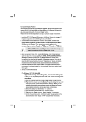
... on VGA card is inserted to the steps below. C. Select the display icon identified by the number 2. E. Please refer to enter BIOS setup. Press to page 17 for proper expansion card installation procedures for the second monitor. Enter "Share Memory" option to adjust the memory...be designated as appropriate for details. 2. When you wish to set up a multi-monitor display. F. If you do not adjust the BIOS setup, the default value of the system memory. Right-click the display icon and select "Attached", if necessary. Surround Display Feature This motherboard...
... on VGA card is inserted to the steps below. C. Select the display icon identified by the number 2. E. Please refer to enter BIOS setup. Press to page 17 for proper expansion card installation procedures for the second monitor. Enter "Share Memory" option to adjust the memory...be designated as appropriate for details. 2. When you wish to set up a multi-monitor display. F. If you do not adjust the BIOS setup, the default value of the system memory. Right-click the display icon and select "Attached", if necessary. Surround Display Feature This motherboard...
User Manual
Page 21
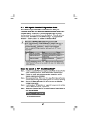
... future driver update and the latest information. ATI Catalyst Control Center 21 Please refer to [Enabled]. Install one compatible PCI Express graphics card to enter BIOS setup. Boot your computer. Step 5. What does an ATITM Hybrid CrossFireXTM system include? Enter "Advanced" screen, and enter "Chipset Settings". Restart your system. 2 . 6 ATITM Hybrid...
... future driver update and the latest information. ATI Catalyst Control Center 21 Please refer to [Enabled]. Install one compatible PCI Express graphics card to enter BIOS setup. Boot your computer. Step 5. What does an ATITM Hybrid CrossFireXTM system include? Enter "Advanced" screen, and enter "Chipset Settings". Restart your system. 2 . 6 ATITM Hybrid...
User Manual
Page 23
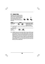
.... 23 The data in CMOS. After waiting for 15 seconds, use a jumper cap to clear the CMOS when you just finish updating the BIOS, you update the BIOS. If you to default setup, please turn off the computer and unplug the power cord from the power supply. Clear CMOS Jumper (CLRCMOS1) (see...
.... 23 The data in CMOS. After waiting for 15 seconds, use a jumper cap to clear the CMOS when you just finish updating the BIOS, you update the BIOS. If you to default setup, please turn off the computer and unplug the power cord from the power supply. Clear CMOS Jumper (CLRCMOS1) (see...

User Manual
Page 26
... Windows system. Click the icon on the chassis must support HDA to enter Realtek HD Audio Manager. Please connect the chassis speaker to [Enabled]. Enter BIOS Setup Utility. G. If you use AC'97 audio panel, please install it to install your system. 2. System Panel Header (9-pin PANEL1) (see p.11 No. 23...
... Windows system. Click the icon on the chassis must support HDA to enter Realtek HD Audio Manager. Please connect the chassis speaker to [Enabled]. Enter BIOS Setup Utility. G. If you use AC'97 audio panel, please install it to install your system. 2. System Panel Header (9-pin PANEL1) (see p.11 No. 23...

User Manual
Page 31
... want to install Windows® XP / XP 64-bit on the screen, "Generate Serial ATA driver diskette [YN]?", press . Insert the ASRock Support CD into the floppy diskette. 31 ROM as the boot device. Then, the drivers compatible to [RAID]. During POST at the beginning... system. Therefore, the drivers you install can be auto-detected and listed on a RAID disk composed of system boot-up BIOS. B. Please select CD- Enter BIOS SETUP UTILITY Advanced screen Storage Configuration. Then you will start Please insert a floppy diskette into the floppy drive, and press ...
... want to install Windows® XP / XP 64-bit on the screen, "Generate Serial ATA driver diskette [YN]?", press . Insert the ASRock Support CD into the floppy diskette. 31 ROM as the boot device. Then, the drivers compatible to [RAID]. During POST at the beginning... system. Therefore, the drivers you install can be auto-detected and listed on a RAID disk composed of system boot-up BIOS. B. Please select CD- Enter BIOS SETUP UTILITY Advanced screen Storage Configuration. Then you will start Please insert a floppy diskette into the floppy drive, and press ...

User Manual
Page 32
...174; XP / XP 64-bit OS on your system. STEP 2: Use "RAID Installation Guide" to set RAID configuration. Please refer to the BIOS RAID installation guide part of 2 or more SATA / SATAII HDDs with RAID functions, please follow below steps. Select the driver to install according to.... Before you start to [RAID]. When prompted, insert the SATA / SATAII driver diskette containing the AMD RAID driver. Then, please set up BIOS. Enter BIOS SETUP UTILITY Advanced screen Storage Configuration. A. Set the "SATA Operation Mode" option to install Windows® XP / XP 64-bit OS on ...
...174; XP / XP 64-bit OS on your system. STEP 2: Use "RAID Installation Guide" to set RAID configuration. Please refer to the BIOS RAID installation guide part of 2 or more SATA / SATAII HDDs with RAID functions, please follow below steps. Select the driver to install according to.... Before you start to [RAID]. When prompted, insert the SATA / SATAII driver diskette containing the AMD RAID driver. Then, please set up BIOS. Enter BIOS SETUP UTILITY Advanced screen Storage Configuration. A. Set the "SATA Operation Mode" option to install Windows® XP / XP 64-bit OS on ...

User Manual
Page 33
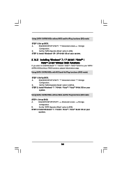
...OS you want to install Windows® XP / XP 64-bit on your SATA / SATAII HDDs without RAID functions, please follow below steps. Enter BIOS SETUP UTILITY Advanced screen Storage Configuration. At the beginning of Windows® setup, press F6 to [AHCI]. STEP 4: Install Windows® XP /...XP / XP 64-bit OS on your system. B. Using SATA / SATAII HDDs with NCQ and Hot Plug functions (AHCI mode) STEP 1: Set Up BIOS. Set the "SATA Operation Mode" option to install a third-party AHCI driver. You can start to the OS you install. 2.14.1 Installing Windows&#...
...OS you want to install Windows® XP / XP 64-bit on your SATA / SATAII HDDs without RAID functions, please follow below steps. Enter BIOS SETUP UTILITY Advanced screen Storage Configuration. At the beginning of Windows® setup, press F6 to [AHCI]. STEP 4: Install Windows® XP /...XP / XP 64-bit OS on your system. B. Using SATA / SATAII HDDs with NCQ and Hot Plug functions (AHCI mode) STEP 1: Set Up BIOS. Set the "SATA Operation Mode" option to install a third-party AHCI driver. You can start to the OS you install. 2.14.1 Installing Windows&#...
User Manual
Page 34
... VistaTM / VistaTM 64-bit OS on your system. A. Using SATA / SATAII HDDs without NCQ and Hot Plug functions (IDE mode) STEP 1: Set up BIOS. A. STEP 2: Install Windows® 7 / 7 64-bit / VistaTM / VistaTM 64-bit OS on your system. 34 Using SATA / SATAII HDDs without... RAID functions, please follow below steps. Set the "SATA Operation Mode" option to [IDE]. Enter BIOS SETUP UTILITY Advanced screen Storage Configuration. STEP 2: Install Windows® XP / XP 64-bit OS on your system. 2.14.2 Installing Windows®...
... VistaTM / VistaTM 64-bit OS on your system. A. Using SATA / SATAII HDDs without NCQ and Hot Plug functions (IDE mode) STEP 1: Set up BIOS. A. STEP 2: Install Windows® 7 / 7 64-bit / VistaTM / VistaTM 64-bit OS on your system. 34 Using SATA / SATAII HDDs without... RAID functions, please follow below steps. Set the "SATA Operation Mode" option to [IDE]. Enter BIOS SETUP UTILITY Advanced screen Storage Configuration. STEP 2: Install Windows® XP / XP 64-bit OS on your system. 2.14.2 Installing Windows®...
User Manual
Page 35
... environment. Please refer to the warning on page 8 for the possible overclocking risk before you enable Untied Overclocking function, please enter "Overclock Mode" option of BIOS setup to set the selection from [Auto] to fixed PCI / PCIE buses. Before you apply Untied Overclocking Technology. 35
... environment. Please refer to the warning on page 8 for the possible overclocking risk before you enable Untied Overclocking function, please enter "Overclock Mode" option of BIOS setup to set the selection from [Auto] to fixed PCI / PCIE buses. Before you apply Untied Overclocking Technology. 35
User Manual
Page 36
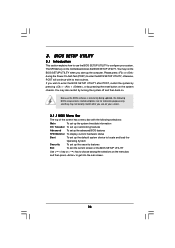
...POST, restart the system by pressing + + , or by turning the system off and then back on the motherboard stores the BIOS SETUP UTILITY. Because the BIOS software is constantly being updated, the following selections: Main To set up the system time/date information OC Tweaker To set up ...overclocking features Advanced To set up the advanced BIOS features H/W Monitor To display current hardware status Boot To set up the default system device to locate and load the Operating System Security...
...POST, restart the system by pressing + + , or by turning the system off and then back on the motherboard stores the BIOS SETUP UTILITY. Because the BIOS software is constantly being updated, the following selections: Main To set up the system time/date information OC Tweaker To set up ...overclocking features Advanced To set up the advanced BIOS features H/W Monitor To display current hardware status Boot To set up the default system device to locate and load the Operating System Security...


