User Manual
Page 2
...motherboard contains Perchlorate, a toxic substance controlled in advance. When you discard the Lithium battery in California, USA, please follow the related regulations in Perchlorate Best Management Practices (BMP) regulations passed by the California Legislature. "Perchlorate Material-special handling may apply, see www.dtsc.ca.gov/hazardouswaste/perchlorate" ASRock...errors or omissions that may cause undesired operation. Operation is subject to infringe. ASRock assumes no event shall ASRock, its directors, officers, employees, or agents be reproduced, transcribed, transmitted, or...
...motherboard contains Perchlorate, a toxic substance controlled in advance. When you discard the Lithium battery in California, USA, please follow the related regulations in Perchlorate Best Management Practices (BMP) regulations passed by the California Legislature. "Perchlorate Material-special handling may apply, see www.dtsc.ca.gov/hazardouswaste/perchlorate" ASRock...errors or omissions that may cause undesired operation. Operation is subject to infringe. ASRock assumes no event shall ASRock, its directors, officers, employees, or agents be reproduced, transcribed, transmitted, or...
User Manual
Page 3
Introduction 5 1.1 Package Contents 5 1.2 Specifications 6 1.3 Motherboard Layout 12 1.4 I/O Panel 13 2 . Installation 15 Pre-installation Precautions 15 2.1 CPU Installation 16 2.2 Installation of CPU Fan and Heatsink 16 2.3 Installation of Memory Modules (DIMM ...
Introduction 5 1.1 Package Contents 5 1.2 Specifications 6 1.3 Motherboard Layout 12 1.4 I/O Panel 13 2 . Installation 15 Pre-installation Precautions 15 2.1 CPU Installation 16 2.2 Installation of CPU Fan and Heatsink 16 2.3 Installation of Memory Modules (DIMM ...

User Manual
Page 5
.../support/index.asp 1.1 Package Contents ASRock 890FX Deluxe4 Motherboard (ATX Form Factor: 12.0-in x 9.6-in, 30.5 cm x 24.4 cm) ASRock 890FX Deluxe4 Quick Installation Guide ASRock 890FX Deluxe4 Support CD 1 x Ultra ATA 66/100/133 IDE Ribbon Cable (80-conductor) 1 x Ribbon Cable for purchasing ASRock 890FX Deluxe4 motherboard, a reliable motherboard produced under ASRock's consistently stringent quality control. It delivers excellent performance with robust design conforming to...
.../support/index.asp 1.1 Package Contents ASRock 890FX Deluxe4 Motherboard (ATX Form Factor: 12.0-in x 9.6-in, 30.5 cm x 24.4 cm) ASRock 890FX Deluxe4 Quick Installation Guide ASRock 890FX Deluxe4 Support CD 1 x Ultra ATA 66/100/133 IDE Ribbon Cable (80-conductor) 1 x Ribbon Cable for purchasing ASRock 890FX Deluxe4 motherboard, a reliable motherboard produced under ASRock's consistently stringent quality control. It delivers excellent performance with robust design conforming to...

User Manual
Page 9
... may be less than 4GB for the reservation for system usage under Windows® environment. This motherboard supports Dual Channel Memory Technology. ASRock website http://www.asrock.com 5. It is supported with AM3 CPU only, and in advance. The voltage regulator can enjoy... to improve efficiency when the CPU cores are idle. ASRock website: http://www.asrock.com 9 CAUTION! 1. ASRock UCC (Unlock CPU Core) feature simplifies AMD CPU activation. As long as a simple switch of ASRock OC Tuner. This motherboard supports Untied Overclocking Technology. If you adopt. For Windows...
... may be less than 4GB for the reservation for system usage under Windows® environment. This motherboard supports Dual Channel Memory Technology. ASRock website http://www.asrock.com 5. It is supported with AM3 CPU only, and in advance. The voltage regulator can enjoy... to improve efficiency when the CPU cores are idle. ASRock website: http://www.asrock.com 9 CAUTION! 1. ASRock UCC (Unlock CPU Core) feature simplifies AMD CPU activation. As long as a simple switch of ASRock OC Tuner. This motherboard supports Untied Overclocking Technology. If you adopt. For Windows...
User Manual
Page 10
... as a game joystick to record the OC settings and share with your friends! With this motherboard offers stepless control, it is the world's first utility to access ASRock Instant Flash. It helps you can start experiencing the exciting motion controlled games. To experience intuitive...BIOS update tool allows you can update your motherboard, and also download the free AIWI Lite from ASRock official website or ASRock software support CD to your BIOS only in Flash ROM. ASRock Instant Flash is just to install the ASRock AIWI utility either from App store to RAM...
... as a game joystick to record the OC settings and share with your friends! With this motherboard offers stepless control, it is the world's first utility to access ASRock Instant Flash. It helps you can start experiencing the exciting motion controlled games. To experience intuitive...BIOS update tool allows you can update your motherboard, and also download the free AIWI Lite from ASRock official website or ASRock software support CD to your BIOS only in Flash ROM. ASRock Instant Flash is just to install the ASRock AIWI utility either from App store to RAM...
User Manual
Page 11
... automatically shutdown. Before you install the PC system. 15. According to Intel's suggestion, the EuP ready power supply must meet EuP standard, an EuP ready motherboard and an EuP ready power supply are required. While CPU overheat is higher than 50% under 1.00W in off mode condition. For EuP ready power... European Union to spray thermal grease between the CPU and the heatsink when you resume the system, please check if the CPU fan on the motherboard functions properly and unplug the power cord, then plug it back again.
... automatically shutdown. Before you install the PC system. 15. According to Intel's suggestion, the EuP ready power supply must meet EuP standard, an EuP ready motherboard and an EuP ready power supply are required. While CPU overheat is higher than 50% under 1.00W in off mode condition. For EuP ready power... European Union to spray thermal grease between the CPU and the heatsink when you resume the system, please check if the CPU fan on the motherboard functions properly and unplug the power cord, then plug it back again.
User Manual
Page 12
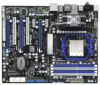
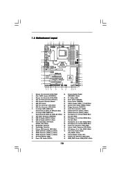
White) (FRONT_1394, White) 38 PCI Express 2.0 x16 Slot (PCIE2; 1.3 Motherboard Layout 45 44 43 42 41 40 39 38 37 36 35 34 33 Bottom: MIC IN Bottom: CTR BASS IEEE 1394 eSATA Coaxial SPDIF ... bit, 240-FpinSBmo8d0ul0e) DDR3_A2 (64 bit, 240-pin module) DDR3_B1 (64 bit, 240-FpinSBmo8d0ul0e) DDR3_B2 (64 bit, 240-pin module) 9 10 IDE1 FRONT_1394 PCI1 Super I/O 890FX Deluxe4 SATA3_8 PCIE4 PCI Express 2.0 ErP/EuP Ready PCI2 RoHS SATA3 6Gb/s NEC USB 3.0 Front USB 3.0 PCIE5 COM1 1 SATA3_7 FLOPPY1 PLED PWRBTN 1 HDLED RESET PANEL 1 USB3_1_2...
White) (FRONT_1394, White) 38 PCI Express 2.0 x16 Slot (PCIE2; 1.3 Motherboard Layout 45 44 43 42 41 40 39 38 37 36 35 34 33 Bottom: MIC IN Bottom: CTR BASS IEEE 1394 eSATA Coaxial SPDIF ... bit, 240-FpinSBmo8d0ul0e) DDR3_A2 (64 bit, 240-pin module) DDR3_B1 (64 bit, 240-FpinSBmo8d0ul0e) DDR3_B2 (64 bit, 240-pin module) 9 10 IDE1 FRONT_1394 PCI1 Super I/O 890FX Deluxe4 SATA3_8 PCIE4 PCI Express 2.0 ErP/EuP Ready PCI2 RoHS SATA3 6Gb/s NEC USB 3.0 Front USB 3.0 PCIE5 COM1 1 SATA3_7 FLOPPY1 PLED PWRBTN 1 HDLED RESET PANEL 1 USB3_1_2...
User Manual
Page 15
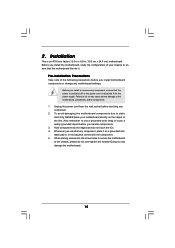
... or the like. Hold components by the edges and do not over-tighten the screws! Before you install the motherboard, study the configuration of the following precautions before you handle components. 3. Before you uninstall any component, ensure that the... motherboard fits into the screw holes to secure the motherboard to the motherboard, peripherals, and/or components. 1. Also remember to do so may damage the motherboard. 15 Whenever you install or remove any component, place it . Doing ...
... or the like. Hold components by the edges and do not over-tighten the screws! Before you install the motherboard, study the configuration of the following precautions before you handle components. 3. Before you uninstall any component, ensure that the... motherboard fits into the screw holes to secure the motherboard to the motherboard, peripherals, and/or components. 1. Also remember to do so may damage the motherboard. 15 Whenever you install or remove any component, place it . Doing ...
User Manual
Page 16
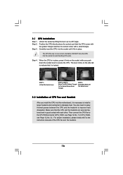
... need to spray thermal grease between the CPU and the heatsink to a 90o angle. 2.1 CPU Installation Step 1. Step 3. DO NOT force the CPU into this motherboard, it is necessary to install a larger heatsink and cooling fan to secure the CPU. Step 4. Lever 90° Up STEP 1: Lift Up The Socket Lever...
... need to spray thermal grease between the CPU and the heatsink to a 90o angle. 2.1 CPU Installation Step 1. Step 3. DO NOT force the CPU into this motherboard, it is necessary to install a larger heatsink and cooling fan to secure the CPU. Step 4. Lever 90° Up STEP 1: Lift Up The Socket Lever...
User Manual
Page 17
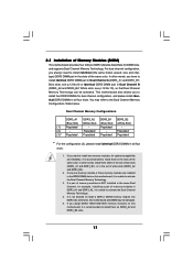
..., and please install identical DDR3 DIMMs in the slots of blue slots (DDR3_A1 and DDR3_B1), or in all four slots. Blue slots; This motherboard also allows you always need to install them either in the set of the same color. Populated - Populated (3)* Populated Populated Populated Populated * ...Technology . 4. You may be activated. If only one memory module or three memory modules are installed in the DDR3 DIMM slots on this motherboard, it is recommended to install identical (the same brand, speed, size and chiptype) DDR3 DIMM pair in DDR3_A1 and DDR3_A2, it is not...
..., and please install identical DDR3 DIMMs in the slots of blue slots (DDR3_A1 and DDR3_B1), or in all four slots. Blue slots; This motherboard also allows you always need to install them either in the set of the same color. Populated - Populated (3)* Populated Populated Populated Populated * ...Technology . 4. You may be activated. If only one memory module or three memory modules are installed in the DDR3 DIMM slots on this motherboard, it is recommended to install identical (the same brand, speed, size and chiptype) DDR3 DIMM pair in DDR3_A1 and DDR3_A2, it is not...
User Manual
Page 18
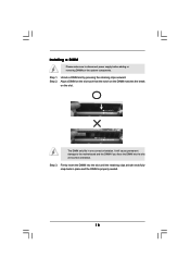
Installing a DIMM Please make sure to the motherboard and the DIMM if you force the DIMM into the slot until the retaining clips at incorrect orientation. Unlock a DIMM slot by pressing the retaining ...
Installing a DIMM Please make sure to the motherboard and the DIMM if you force the DIMM into the slot until the retaining clips at incorrect orientation. Unlock a DIMM slot by pressing the retaining ...
User Manual
Page 19
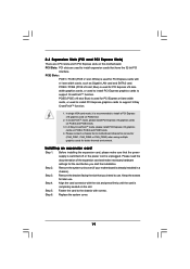
...slot that you start the installation. Step 5. In single VGA card mode, it is already installed in a chassis). Remove the system unit cover (if your motherboard is recommended to install a PCI Express x16 graphics card on the slot. Replace the system cover. 19 PCIE2 / PCIE4 (PCIE x16 slot; PCIE5 (PCIE ... better thermal environment. Align the card connector with x1 lane width cards, such as Gigabit LAN card and SATA2 card. Fasten the card to motherboard chassis fan connector (CHA_FAN1, CHA_FAN2 or CHA_FAN3) when using multiple graphics cards for later use . Step 6.
...slot that you start the installation. Step 5. In single VGA card mode, it is already installed in a chassis). Remove the system unit cover (if your motherboard is recommended to install a PCI Express x16 graphics card on the slot. Replace the system cover. 19 PCIE2 / PCIE4 (PCIE x16 slot; PCIE5 (PCIE ... better thermal environment. Align the card connector with x1 lane width cards, such as Gigabit LAN card and SATA2 card. Fasten the card to motherboard chassis fan connector (CHA_FAN1, CHA_FAN2 or CHA_FAN3) when using multiple graphics cards for later use . Step 6.
User Manual
Page 20
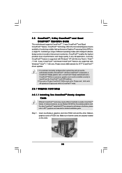
...CrossFireXTM feature are properly seated on the slots. 20 All three CrossFireXTM components, a CrossFireXTM Ready graphics card, a CrossFireXTM Ready motherboard and a CrossFireXTM Edition co-processor graphics card, must be installed correctly to ATITM graphics card manuals for ATITM CrossFireXTM driver updates...or will operate as the example graphics card. 2.5 CrossFireXTM, 3-Way CrossFireXTM and Quad CrossFireXTM Operation Guide This motherboard supports CrossFireXTM, 3-way CrossFireXTM and Quad CrossFireXTM feature. Please check AMD website for detailed installation guide. If ...
...CrossFireXTM feature are properly seated on the slots. 20 All three CrossFireXTM components, a CrossFireXTM Ready graphics card, a CrossFireXTM Ready motherboard and a CrossFireXTM Edition co-processor graphics card, must be installed correctly to ATITM graphics card manuals for ATITM CrossFireXTM driver updates...or will operate as the example graphics card. 2.5 CrossFireXTM, 3-Way CrossFireXTM and Quad CrossFireXTM Operation Guide This motherboard supports CrossFireXTM, 3-way CrossFireXTM and Quad CrossFireXTM feature. Please check AMD website for detailed installation guide. If ...
User Manual
Page 21
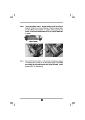
... the Radeon graphics card on the top of Radeon graphics cards. (CrossFire Bridge is provided with the graphics card you purchase, not bundled with this motherboard. Please refer to D-Sub adapter.) 21 Connect two Radeon graphics cards by installing CrossFire Bridge on CrossFire Bridge Interconnects on PCIE2 slot. (You may use...
... the Radeon graphics card on the top of Radeon graphics cards. (CrossFire Bridge is provided with the graphics card you purchase, not bundled with this motherboard. Please refer to D-Sub adapter.) 21 Connect two Radeon graphics cards by installing CrossFire Bridge on CrossFire Bridge Interconnects on PCIE2 slot. (You may use...
User Manual
Page 22
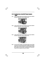
... card to connect Radeon graphics cards on PCIE4 and PCIE5 slots. (CrossFireTM Bridge is provided with the graphics card you purchase, not bundled with this motherboard. 2.5.1.2 Installing Three CrossFireXTM-Ready Graphics Cards Step 1. Step 2. For the proper installation procedures, please refer to section "Expansion Slots". Step 4. Install one Radeon graphics card...
... card to connect Radeon graphics cards on PCIE4 and PCIE5 slots. (CrossFireTM Bridge is provided with the graphics card you purchase, not bundled with this motherboard. 2.5.1.2 Installing Three CrossFireXTM-Ready Graphics Cards Step 1. Step 2. For the proper installation procedures, please refer to section "Expansion Slots". Step 4. Install one Radeon graphics card...
User Manual
Page 26
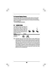
... document at the following path in CMOS includes system setup information such as system password, date, time, and system setup parameters. 2.6 Surround Display Feature This motherboard supports Surround Display upgrade. The data in the Support CD: ..\ Surround Display Information 2.7 Jumpers Setup The illustration shows how jumpers are "Short" when jumper cap...
... document at the following path in CMOS includes system setup information such as system password, date, time, and system setup parameters. 2.6 Surround Display Feature This motherboard supports Surround Display upgrade. The data in the Support CD: ..\ Surround Display Information 2.7 Jumpers Setup The illustration shows how jumpers are "Short" when jumper cap...
User Manual
Page 27
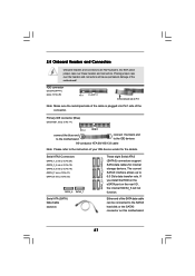
...12 No. 29) Pin1 FLOPPY1 the red-striped side to 6.0 Gb/s data transfer rate. If you install the HDD on the eSATA port on this motherboard. 27 Primary IDE connector (Blue) (39-pin IDE1, see p.12, No. 32) SATA3_8 SATA3_7 Serial ATA (SATA) Data Cable (Optional) SATA3_1_2 SATA3_3_4...(SATA3) connectors support SATA data cables for the details. Either end of the SATA data cable can be connected to the instruction of the motherboard! Placing jumper caps over these headers and connectors. Do NOT place jumper caps over the headers and connectors will not function. 2.8 Onboard Headers...
...12 No. 29) Pin1 FLOPPY1 the red-striped side to 6.0 Gb/s data transfer rate. If you install the HDD on the eSATA port on this motherboard. 27 Primary IDE connector (Blue) (39-pin IDE1, see p.12, No. 32) SATA3_8 SATA3_7 Serial ATA (SATA) Data Cable (Optional) SATA3_1_2 SATA3_3_4...(SATA3) connectors support SATA data cables for the details. Either end of the SATA data cable can be connected to the instruction of the motherboard! Placing jumper caps over these headers and connectors. Do NOT place jumper caps over the headers and connectors will not function. 2.8 Onboard Headers...
User Manual
Page 28
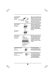
...GND DUMMY 1 GND P+12 P-12 USB_PWR Besides six default USB 2.0 ports on the I /O panel, there is one USB 3.0 header on this motherboard. IntA_P2_D+ IntA_P2_DGND IntA_P2_SSTX+ IntA_P2_SSTXGND IntA_P2_SSRX+ IntA_P2_SSRXVbus 1 Vbus IntA_P1_SSRXIntA_P1_SSRX+ GND IntA_P1_SSTXIntA_P1_SSTX+ GND IntA_P1_DIntA_P1_D+ ID Besides two default USB 3.0 ports on the I /O ... connect the black end of SATA power cable to the power connector of SATA power cable to the power connector on this motherboard. Infrared Module Header (5-pin IR1) (see p.12 No. 43) IRTX +5V DUMMY 1 GND IRRX This header supports ...
...GND DUMMY 1 GND P+12 P-12 USB_PWR Besides six default USB 2.0 ports on the I /O panel, there is one USB 3.0 header on this motherboard. IntA_P2_D+ IntA_P2_DGND IntA_P2_SSTX+ IntA_P2_SSTXGND IntA_P2_SSRX+ IntA_P2_SSRXVbus 1 Vbus IntA_P1_SSRXIntA_P1_SSRX+ GND IntA_P1_SSTXIntA_P1_SSTX+ GND IntA_P1_DIntA_P1_D+ ID Besides two default USB 3.0 ports on the I /O ... connect the black end of SATA power cable to the power connector of SATA power cable to the power connector on this motherboard. Infrared Module Header (5-pin IR1) (see p.12 No. 43) IRTX +5V DUMMY 1 GND IRRX This header supports ...
User Manual
Page 31
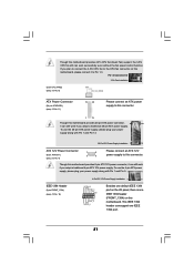
... Power Connector (24-pin ATXPWR1) (see p.12 No. 11) 12 24 Please connect an ATX power supply to this connector. 1 13 Though this motherboard provides 4-Pin CPU fan (Quiet Fan) support, the 3-Pin CPU fan still can work successfully even without the fan speed control function. Though this... 5. 1 4 IEEE 1394 Header (9-pin FRONT_1394) (see p.12 No. 4) 5 8 Please connect an ATX 12V power supply to this motherboard, please connect it to the CPU fan connector on this motherboard provides 8-pin ATX 12V power connector, it can still work if you plan to connect the 3-Pin CPU fan to...
... Power Connector (24-pin ATXPWR1) (see p.12 No. 11) 12 24 Please connect an ATX power supply to this connector. 1 13 Though this motherboard provides 4-Pin CPU fan (Quiet Fan) support, the 3-Pin CPU fan still can work successfully even without the fan speed control function. Though this... 5. 1 4 IEEE 1394 Header (9-pin FRONT_1394) (see p.12 No. 4) 5 8 Please connect an ATX 12V power supply to this motherboard, please connect it to the CPU fan connector on this motherboard provides 8-pin ATX 12V power connector, it can still work if you plan to connect the 3-Pin CPU fan to...
User Manual
Page 33
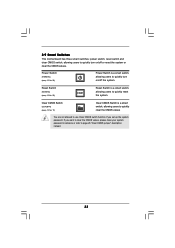
2.9 Smart Switches This motherboard has three smart switches: power switch, reset switch and clear CMOS switch, allowing users to quickly turn on /off the system. If you set up ...
2.9 Smart Switches This motherboard has three smart switches: power switch, reset switch and clear CMOS switch, allowing users to quickly turn on /off the system. If you set up ...

